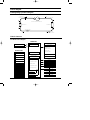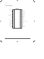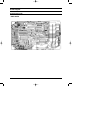
1
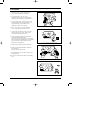
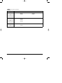
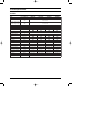
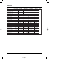
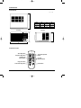
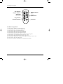
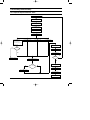
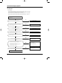
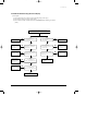
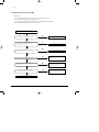
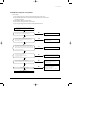
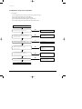
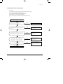
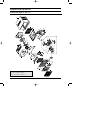
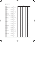
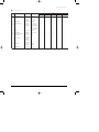
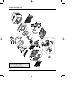
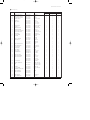
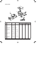
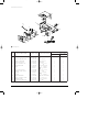
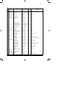
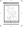
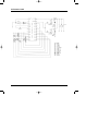
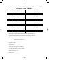
DB98-04511A(1)-CO
3/20/02 2:28 PM
Page 2
ROOM AIR CONDITIONER
AW078AA
AW088AA
AW108AA
AW128AA
SERVICE
AIR CONDITIONER
AW069AB
AW089AB
AW109AB
AW129AB
Manual
CONTENTS
1. Precautions
2. Product Specifications
3. Installation and Operating
Instructions
4. Disassembly and Reassembly
5. Troubleshooting
6. Exploded Views and Parts List
7. Block Diagram
8. Wiring Diagram
DB98-04511A(1)-1
3/20/02 2:23 PM
Page 1-1
1. Precautions
1. Warning: Prior to repair, disconnect the
power cord from the circuit breaker.
2. Use proper parts: Use only exact
replacement parts. (Also, we recommend
replacing parts rather than repairing them.)
3. Use the proper tools: Use the proper tools
and test equipment, and know how to use
equipment may cause problems laterintermittent contact, for example.
Fig. 1-1 Avoid Dangerous Contact
4. Power Cord: Prior to repair, check the
power cord and replace it if necessary.
5. Avoid using an extension cord, and avoid
tapping into a power cord. This practice
may result in malfunction or fire.
6. After completing repairs and reassembly,
check the insulation resistance.
Procedure: Prior to applying power, measure
the resistance between the power cord and the
ground terminal. The resistance must be
greater than 30 megaohms.
Fig. 1-2 No Tapping and No Extension Cords
7. Make sure that the grounds are adequate.
8. Make sure that the installation conditions
are satisfactory.
Relocate the unit if necessary.
9. Keep children away from the unit while it is
being repaired.
10. Be sure to clean the unit and its surrounding
area.
Fig. 1-3 No Kids Nearby!
Fig. 1-4 Clean the Unit
Samsung Electronics
1-1
DB98-04511A(1)-1
3/20/02 2:23 PM
Page 1-2
Notice : The symbol of model name
Type
A
Model Name
AW078AA
AW069AB
AW088AA
AW089AB
AW109AB
B
AW128AA
AW129AB
C
1-2
AW108AA
Samsung Electronics
DB98-04511A(1)-1
3/20/02 2:23 PM
Page 2-1
2. Product Specifications
2-1 Table
Item
Unit of Measure
Type
-
WINDOW
Dimensions:
(Width×Height× Depth)
mm
520×345× 485
Packing size:
(Width×Height× Depth)
mm
571×454× 546
Voltage
Volt
Phase
Hz
Operating Current
A
Power Consumption
W
Refrigerant Charge
Capacity
EER
Net Weight
AW088AA
AW089AB
Single
FREON
R22
g
BTU/h
BTU/h.W
kg
Condenser
Row
Condenser Fan
Type
Evaporator
Row
Evaporator Fan
Type
Fan Motor
Model
Compressor(Rotary)
Model
Overload Protect
AW078AA
-
Frequency
Refrigerant Type
AW069AB
-
3×15
2×15
2×15
3×15
2×14
3×14
Propeller Fan
2×14
2×14
Blower
YGN55-6F
YGN55-6E
YGN55-6B
YGN55-6B
44C062HU1EA
44A072HW1EB
44A080HU1EB
44A076HU1EB
MRA12040-12008 MRA98706-12008 MRA12083-12008 MRA12083-12008
Compressor Capacitor
F/VAC
35/370
25/370
35/370
35/370
Fan Motor Capacitor
F/VAC
5/250
6/450
6/250
6/250
Fan speed
RPM
780/750/670
780/720/650
880/780/710
880/780/710
Thermo Control
Air Swing
Samsung Electronics
-
THERMISTOR
Model
M2CK59ZT79-H
2-1
DB98-04511A(1)-1
3/20/02 2:23 PM
Page 2-2
Table (cont.)
Item
Unit of Measure
AW108AA
AW109AB
Type
AW128AA
mm
550×345× 485
660×394× 595
Packing size:
(Width×Height×Depth)
mm
590×468× 578
728×459× 647
Voltage
Volt
Hz
Operating Current
A
Refrigerant Type
Refrigerant Charge
Capacity
EER
Net Weight
W
FREON
BTU/h
BTU/h.W
kg
Row
Condenser Fan
Type
Evaporator
Row
Evaporator Fan
Type
Fan Motor
Model
Compressor(Rotary)
Model
Compressor Capacitor
F/VAC
Fan Motor Capacitor
F/VAC
Fan speed
RPM
Thermo Control
Air Swing
2-2
R22
g
Condenser
Overload Protect
Single
-
Frequency
Power Consumption
Remarks
WINDOW
Dimensions:
(Width×Height×Depth)
Phase
AW129AB
3×15
3×17
3×17
3×17
3×16
2×14
Propeller Fan
2×12
2×16
YGN61-6A
YFK70-6A
YGN60-6B
YGN60-6G
44B098HU2EF
44B098HU2EF
44B124HX1EL
44B124HX1EL
Blower
MRA12132-12007 MRA12132-12007 MRA98693-12007 MRA98693-12007
45/370
45/370
50/370
50/370
15/250
8/250
15/250
15/250
1020/970/900
880/800/740
880/780/710
880/780/710
-
THERMISTOR
Model
M2CK59ZT79-H
Samsung Electronics
DB98-04511A(1)-1
3/20/02 2:23 PM
Page 2-3
2-2 Dimensions
2-2-1 Main Unit
(Unit : mm)
D
Front view
Type
W
H
D
A
520
345
485
B
600
394
595
C
550
345
485
Side view
H
H
W
2-2-2 Remote Control
Timer setting button
Sleep timer setting button
Operating mode
selection buttons
Temperature adjustment
buttons
Fan speed
adjustment buttons
Energy Saver button
Air flow blade swing button
Samsung Electronics
ON/OFF button
2-3
DB98-04511A(1)-1
3/20/02 2:23 PM
Page 2-4
MEMO
2-4
Samsung Electronics
DB98-04511A(1)-1
3/20/02 2:23 PM
Page 3-1
3. Installation and Operating Instructions
3-1 Installation
3-1-1 Selecting Area for Installation
1.
Make sure that you install the unit in an area
providing good ventilation. The air conditioner
must not be blocked by any obstacle affecting the
air flow near the air inlet and air outlet.
2. Make sure that you install the unit in an area that
allow good air handling. The installation area must
be able to endure vibration from the unit.
3. Make sure that you install the unit away from heat
or vapor.
4. Make sure that you install the unit in an area
which is cool and has adequate space.
5.
6. Make sure that you install the unit in an area which
provides easy drainage for condensed water.
7. Make sure that you install the unit in an area not
exposed to rain or direct sunlight.
(Install a separate sunblind if exposed to direct
sunlight.)
8. Make sure that you install the unit in an area
allowing good air movement. Do not install it in
a space that would cause noise amplification of
noise.
9.
Fix the unit firmly if mounted in a high place.
Make sure that you install the unit in an area away
from TVs, audio units, cordless phones,
fluorescent lighting fixtures and other electrical
appliances (obtain a clearance of at least one meter).
Caution:
Do not use the air conditioner in the following environments : greasy areas (including areas near
machines), or marine areas. Contact your local dealer for advice.
Samsung Electronics
3-1
DB98-04511A(1)-1
3/20/02 2:23 PM
Page 3-2
3-2 Function Description
Fan speed indicator
(LOW, MED, HIGH)
Temperature/Timer settings
Air flow blade swing indicator
Energy saver indicator
ON/OFF Timer adjustment button
Temperature
adjustment buttons
Sleep adjustment button
Operating mode indicators
(COOL, FAN)
Remote control sensor
Air flow blade swing button
Timer indicator
Energy saver button
Fan Speed adjustment button
Operating mode selection button
Operating on/off
3-2-1 Cooling operation mode
The compressor is turned on and off according to the ambient temperature and set temperature.
1) Compressor on and off control
• Compressor on and off control according to the ambient temperature
* The compressor is turned off when "ambient temperature = set temperature
* The compressor is turned on when "ambient temperature = set temperature +1˚C"
2) Default value after power reset ➔ set temperature = 24˚C
Fan speed = High
3) Set temperature indicating (setting) range : 1˚C interval from 18˚C to 30˚C.
3-2-2 Fan operation mode
1) If "Fan operation mode" signal is received from remocon or panel.
➔ the compressor is immediately turned off and only fan motor is operated at set blowing speed.
➔ it changes such as "High ➔ Med ➔ Low ➔ High"( if Fan speed is selected).
2) The initial Fan motor speed is set to "High".
3) The set temperature can not be indicated and set.
3-2-3 Energy saver operation mode
* If the compressor turn off at the cooling operation, the fan motor turn off after operation during the fixation time only,
and operation that energy saver by turn off the fixation time only, and operation that energy saver by turn off the motor
continuously before the condition of the compressor on.
* The fan motor is not operated at flow wind operation.
* Energy saver operation specification at the cooling operation.
1) Fan motor control in compressor on : operate with setting wind speed
2) Fan motor control in compressor off : After compressor off, the fan motor is operated breeze for 2 minutes and then it
turn off.
3) After the fan motor off, the compressor and fan motor is operated normally when the compressor on.
3-2
Samsung Electronics
DB98-04511A(1)-1
3/20/02 2:23 PM
Page 3-3
Installation and Operating Instructions
3-2-4 Sleep operation mode
1) Enable to sleep operation only when cooling operation.
2) First, 7-SEG LED DISPLAY "SLEEP" while 15 second, Second, 7-SEG LED DISPLAY "8Hr"
And, automatically SET OFF after operated while 8 Hour
3) If sleep operation, setting Temperature rise 1˚C after 1 Hour
4) ON TIMER operation, not operation, ENERGY SAVER operation, not sleep operation.
3-2-5 Air flow blade swing motor operation
1) The Air flow blade swing motor is turned on and off according to Air flow blade swing operation in remocon or panel,
if SET is cooling or Fan operation mode.
2) If the operation mode is "ENERGY SAVER", in case of fan motor being turned off Air flow blade swing motor is
immediately turned off.
3-2-6 LED display indication in case of error detection
ERROR OPERATION
7-SEG
LED DISPLAY
ROOM THERMISTOR
(OPEN or SHORT)
E1 displayed
1) Set operation in case of error occurrence.
• Malfunction of each temperature sensor (open, short)
- Error mode display, warning sound.
- The operation status is off.
Samsung Electronics
3-3
DB98-04511A(1)-1
3/20/02 2:23 PM
Page 3-4
Installation and Operating Instructions
3-2-7 Panel key operation
Key discription
Key name
POWER
Mode
Fan speed
Temperature
(▲ ▼)
3-4
Key operational function
Operation start and stop
* First ON = operation start, second ON = operation stop
- Selected as "OFF –> COOL or FAN". (DEFAULT=OFF)
* Continuous operation is not available.
Operation mode change
* at every ON
- Selected as "COOL –> FAN". (Default=COOL)
If
* operation is OFF, it is considered as an invalid key.
* Continuous operation is not available.
Fan motor speed setting
* at every ON
- Selected as “HIGH → MED → LOW → HIGH”. (DEFAULT=HIGH)
Currently displayed set temperature increase/decrease
* At every pressing, the set temperature is changed by 1˚C
(increase(▲) : 18˚C → 19˚C → ... → 29˚C → 30˚C)
(decrease(▼) : 24˚C → 23˚C → ... → 17˚C → 18˚C)
* In case of the set temperature of 30˚C, when the “increase” key is pressed
temperature does not increase any more.
* In case of the set temperature of 18˚C, when the “decrease” key is pressed
temperature does not decrease any more.
* In case of above situation, when “increase/decrease“ key is pressed by remocon,
warning sound is generated.
* If operation is OFF, it is considered as an invalid key.
* In case of “FAN” mode operation, it is considered as an invalid key.
* Continuous operation is available.
Circulaire
Circulaire motor operation and stop
* Once ON=Circulaire motor operation. Another ON-Circulaire motor stop.
* Continuous operation is not available.
* In case of operation stop, when the fan motor is turned off it is considered as an invalid key.
Timer
(ON/OFF)
Setting the on/off timer
* Can set “OFF TIMER HOUR“ if set is operation
* Can set “ON TIMER HOUR“ if set is not operation
* Once ON = standby setting TIMER : “– –“ displayed
* In case of key pressing in status of standby setting ON/OFF TIMER
(––Hr → 1Hr → 2Hr → ... –> 23Hr → 24Hr)
If
* press TIMER key countinuosly operate such the lower part
(––Hr → 1Hr → 2Hr → ... → 24Hr → --Hr)
Continuous
operation is available.
*
Sleep
SLEEP mode on and off
* Once ON=SLEEP mode on, Another ON=SLEEP mode off
• Continuous operation is not abailable
• Operation off, on timer Operation, save operation , not key operation
* Not SLEEP operation is FAN mode
Energy Saver
Power save mode on and off
* Once ON=Power save mode on, Another ON=Power save mode off
* Continuous operation is not available.
* If operation is OFF, it is considered as an invalid key.
Samsung Electronics
DB98-04511A(1)-1
3/20/02 2:23 PM
Page 3-5
Installation and Operating Instructions
3-2-8 LED lamp operation specifications
LAMP name
COOLING
Operations specifications
The mode is set to "COOL" → ON
Others → OFF
FAN
The mode is set to "FAN" → ON
Others → OFF
HIGH
The mode is set to "HIGH" → ON
Others → OFF
MED
The mode is set to "MED" → ON
Others → OFF
LOW
The fan speed is set to "LOW" → ON
Others → OFF
TIMER
The mode is set to "TIMER" → ON
Others → OFF
ENER SAVER
The mode is set to "ENERGY SAVER" → ON
Others → OFF
CIRCULAIRE
The mode is set to "CIRCULAIRE" → ON
Others → OFF
(1)
(3)
(2)
(4)
In case of set temperature display
→ NO. (1) 7–SEG LED DISPLAY indicates temperature of the tens digit
→ NO. (2) 7-SEG LED DISPLAY indicates temperature of the units digit
In case of time display
→ NO. (1) 7–SEG LED DISPLAY indicates time of the tens digit
→ NO. (2) 7–SEG LED DISPLAY indicates time of the units digit
In case of set temperature display
→ NO. (3) 7–SEG LED DISPLAY indicates temperature unit(˚)
→ NO. (4) 7-SEG LED DISPLAY indicates temperature unit(C)
In case of time display
→ NO. (3) 7–SEG LED DISPLAY indicates time unit(H) of the tens digit
→ NO. (4) 7–SEG LED DISPLAY indicates time unit(r) of the units digit
First, 7–SEG LED DISPLAY "SLEEP" while 15 second,
Second, 7-SEG LED DISPLAY "8Hr"
(1) (2) (3) (4)
Samsung Electronics
3-5
DB98-04511A(1)-1
3/20/02 2:23 PM
Page 3-6
3-3 Remocon Control
Timer setting button
Sleep timer setting button
Operating mode
selection buttons
Temperature adjustment
buttons
Fan speed
adjustment buttons
Energy Saver button
Air flow blade swing button
ON/OFF button
3-3-1 Remocon key operation
11) In case of pressing ”POWER” key, operation start and stop.
12) In case of pressing ”COOL” key, cool mode operation start.
13) In case of pressing ”FAN” key, fan mode operation start.
14) In case of pressing ”HIGH” key, fan motor operates high speed.
15) In case of pressing ”MED” key, fan motor operates mid speed.
16) In case of pressing ”LOW” key, fan motor operates low speed.
17) In case of pressing ”ENERGY SAVER” on/off key, set operates as power saving mode.
18) In case of pressing ”▲” key, set temperature increase by 1˚C(18˚C ~ 30˚C).
19) In case of pressing ”▼” key, set temperature decrease by 1˚C(30˚C ~ 18˚C).
10) In case of pressing ”TIMER” key, the convenient reserve TIMER time increase by 1 Hr (1Hr ~ 24Hr).
11) In case of pressing ”SLEEP” key, SLEEP operates.
12) In case of power off, all keys except POWER key are considered as an invalid key.
3-6
Samsung Electronics
DB98-04511A(1)-1
3/20/02 2:23 PM
Page 3-7
Installation and Operating Instructions
3-3-2 Resistor values table of “ROOM THERMISTOR” for each temperature
<Room thermistor>
Temperature
[˚C]
THERMISTOR RESISTOR
[Kohm] ±1%
Temperature
[˚C]
THERMISTOR RESISTOR
[Kohm] ±1%
70
69
68
67
66
65
64
63
62
61
60
2.229
2.296
2.365
2.437
2.512
2.589
2.669
2.752
2.838
2.928
3.021
29
28
27
26
25
24
23
22
21
20
8.622
8.944
9.281
9.632
10.000
10.380
10.780
11.200
11.630
12.090
59
58
57
56
55
54
53
52
51
50
3.116
3.216
3.319
3.426
3.537
3.652
3.772
3.897
4.026
4.161
19
18
17
16
15
14
13
12
11
10
12.560
13.060
13.570
14.120
14.680
15.280
15.900
16.550
17.240
17.960
49
48
47
46
45
44
43
42
41
40
4.300
4.444
4.594
4.749
4.912
5.080
5.256
5.439
5.630
5.828
9
8
7
6
5
4
3
2
1
0
18.700
19.480
20.290
21.150
22.050
22.990
23.900
25.030
26.130
27.280
39
38
37
36
35
34
33
32
31
30
6.033
6.246
6.468
6.699
6.941
7.192
7.455
7.729
8.015
8.313
-1
-2
-3
-4
-5
-6
-7
-8
-9
28.470
29.720
31.040
32.430
33.890
35.430
37.050
38.760
40.560
Samsung Electronics
3-7
DB98-04511A(1)-1
3/20/02 2:23 PM
Page 3-8
MEMO
3-8
Samsung Electronics
DB98-04511A(1)-1
3/20/02 2:23 PM
Page 4-1
4. Disassembly and Reassembly
4-1 Compressor Replacement Flow Chart
Locate cause of defect
Release refrigerant
Disconnect electrical wiring
from compressor
Cut refrigerant lines
from compressor
Plug disconnected lines
Replace compressor
Inspect electrical
wiring for defects,
and terminals for
correct and secure
connections
Solder discharge line
Solder suction line
Use nitrogen gas
Perform soldering function
Y
Problem?
Fill system with nitrogen gas
N
Check for leakage
Y
Leakage?
Corrective action
Check refrigerant oil level
N
Release nitrogen gas?
Y
Low oil level?
N
Evacuate system
Add oil as necessary
Recharge system
Pinch and braze filling tube
Samsung Electronics
4-1
DB98-04511A(1)-1
3/20/02 2:23 PM
Page 4-2
4-2 Checking the oil
Fill the transparent container with 10cc of oil, and then conduct the test.
4-2-1 Oil quality
Oil Condition
Conidition of
Refrigerant Cycle
Color
Odor
Normal
Straw Yellow
No Odor
Return with the system
Over-heated
Brown Color
-
Change the oil
Compressor Damage
Dark Brown
Pungent oil
Change the oil
Remarks
4-2-2 Replacing and refilling the refrigerant oil
1. Change the compressor - DO NOT recharge the oil as the compressor itself is
already charged.
2. Change the condenser .... add 50cc
3. Change the evaporator .... add 50cc
4. When the refrigerant is replaced .... add 30cc oil.
5. After vacuum is completed, the oil is filled through the high pressure side.
6. In the event of a refrigerant leak, generally it is not necessary to add oil.
(Unless the oil has leaked significantly.)
4-2
Samsung Electronics
DB98-04511A(1)-1
3/20/02 2:24 PM
Page 4-3
4-3 Disassembly and Reassembly Procedure (Type “A”)
Stop operating the air conditioner, and pull out the power cord before repair.
No.
!
Part name
Ass'y Grill
Procedures
Remarks
1. Pull the panel front and remove the screw
on the grille.
*The type of front-panel
depends on models.
2. Hold the lower part of grill with two hands
while pressing down on both sides of the
lower part of the cabinet, pull it forward by
about 30, and the then lift it up for removal.
POW
ER
/ MOD
E
@
Ass'y Cabinet
1. Remove the two screws both side cabinet.
2. Pull the front both side, and remove the unit
from the cabinet.
#
Ass'y COVER EVAP
1. Remove 6 screws on the COVER EVAP.
2. Remove the COVER EVAP.
Samsung Electronics
4-3
DB98-04511A(1)-1
3/20/02 2:24 PM
Page 4-4
Disassembly and Reassembly
No.
Part name
$
Ass'y Control
Procedures
Remarks
1. Remove the blade V(and arm blade).
2. Remove 3 screws on the FRAME BLADE.
3. Remove the FRAME BLADE.
4. Remove 1 screw under the Base pan,
and earth wire screw.
5. Remove two lead wire assemblies.
6. Take out the control box forward.
%
PLATE EVAP CASING
&
TRAY DRAIN
1. Remove 2 screws on the front side.
2. Remove 4 screws on the left side.
3. Pull up the PLATE EVAP CASING and
TRAY DRAIN.
^
Blower
&
Propeller Fan
1. Remove 2 screws on the rear side (Base
pan), and 7 screws on the case cond.
2. Pull up the CONDENSER from the Base
pan.
3. Remove the nut, and remove the propeller
fan.
4. Remove the nut, and remove the
BLOWER.
4-4
Samsung Electronics
DB98-04511A(1)-1
3/20/02 2:24 PM
Page 4-5
Disassembly and Reassembly
No.
Part name
&
CASE COND
*
Motor
&
the others parts
Procedures
Remarks
1. Remove the CASE COND.
1. Remove 4 screws on the MOTOR, and
remove the motor.
2. Remove 4 screws on the mounter motor,
and remove the mounter motor.
3. Remove the CASE BLOWER.
4. Remove 4 screws on the PARTITION.
Samsung Electronics
4-5
DB98-04511A(1)-1
3/20/02 2:24 PM
Page 4-6
Disassembly and Reassembly Procedure (cont.) (Type “B”)
Stop operating the air conditioner, and pull out the power cord before repair.
No.
!
Part name
Ass'y Grill
Procedures
Remarks
1. Pull the grille air inlet and remove the screw
on the grille.
*The type of front-panel
depends on models.
2. Hold the lower part of the grill with two
hands while pressing down on both sides of
the lower part of the cabinet, pull it forward
by about 30, and then lift it up for removal.
POW
ER
/ MOD
E
@
Ass'y Cabinet
1. Remove the screws on both sides of the
cabinet to disconnect the cabinet and frame.
2. Pull the handle on the front side of the
bottom, and remove the unit from the
cabinet.
#
COVER-EVAP
1. Remove the 8 screws on the COVER EVAP.
2. Remove the COVER EVAP.
4-6
Samsung Electronics
DB98-04511A(1)-1
3/20/02 2:24 PM
Page 4-7
Disassembly and Reassembly
No.
Part name
$
Ass'y Control
Procedures
Remarks
1. Remove the blade V(and arm blade).
2. Remove 4 screws on the FRAME BLADE.
3. Remove the FRAME BLADE.
4. Remove 2 screws under the BASE PAN, and
earth wire screw.
5. Remove two lead wire assemblies.
6. Take out the control box forward.
%
PLATE EVAP CASING
&
TRAY DRAIN
1. Remove 2 srews on the front side.
2. Remove 3 screws on the left side.
3. Remove 1 screw from the Base pan.
4. Pull up the PLATE EVAP CASING and TRAY
DRAIN.
^
Case Cond
&
Propeller Fan
1. Remove 2 screws on the rear side (Base
pan), and 7 screws on the case cond.
2. Pull up the CONDENSER from the Base pan.
3. Remove the Nut, and remove the propeller
fan.
4. Remove the Nut, and remove the BLOWER.
Samsung Electronics
4-7
DB98-04511A(1)-1
3/20/02 2:24 PM
Page 4-8
Disassembly and Reassembly
No.
Part name
&
CASE COND
*
MOTOR
&
the others parts
Procedures
Remarks
1. Remove the CASE COND.
1. Remove 4 screws on the MOTOR,
and remove the motor.
2. Remove 4 bolts on the mounter motor,
and remove the mounter motor.
3. Remove the CASE EVAP.
4. Remove 4 screws on the partition.
4-8
Samsung Electronics
DB98-04511A(1)-2
3/20/02 2:25 PM
Page 5-1
5. Troubleshooting
Check the basic checkpoints first to determine whether it is machine trouble or a problem in the
operation method. When it is not related to the basic checkpoints, perform checking in accordance
with the procedures of troubleshooting by symptom.
5-1 Basic Checkpoints for Troubleshooting
1) Is the voltage of the power source appropriate ?
(1) It should be within the rating voltage ±10% range.
(2) The air conditioner may not operate properly when the voltage is out of this range.
2) Is the connection with the fan motor, compressor wire, and starting condenser
appropriately made ?
3) The symptoms listed in the table below are not indicative of machine trouble.
Symptom
Cause and check
No operation
• Check whether there is power failure or the power plug is pulled out.
• Check whether the unit is stopped as a result of completion
of the sleep time.
• Pull out the power plug for ten seconds, and then insert it again.
Air flows, but
no cooling
• Check whether the Air filter is clogged with dust or is dirty.
• Check whether the desired temperature is too high. Set the desired
temperature to a lower level than the current temperature.
• Check whether it is in "FAN" mode.
The remocon does
not operate
• Check whether battery is completely depleted.
• Check whether the battery is properly inserted.
• Check whether the receiving window of the remocon for the assembly
main PCB is blinded.
• Check whether the remocon is affected by jamming due to a neon sign.
No temperature
setting
• Check whether the unit is in "FAN" mode.
(In "FAN" mode, only the current temperature is displayed, and the
desired temperature is not set.)
❈ Checking and Display of Fault Area
ERROR OPERATION
ERROR OPERATION
ROOM THERMISTOR (OPEN OR SHORT)
E1 displayed
Samsung Electronics
5-1
DB98-04511A(1)-2
3/20/02 2:25 PM
Page 5-2
5-2 Troubleshooting by Symptom
5-2-1 No power
1) Check points
(1) Is the voltage of the power source normal ? (the rating voltage ±10% range.)
(2) Is the electric wire in good contact ?(CN 71, RY 71)
(3) Is the output voltage of the IC01(KA 7812) normal ?(DC 11.5V ~ DC 12.5V)
(4) Is the output voltage of the IC02(KA 7805) normal ?(DC 4.5V ~ DC 5.5V)
Turn off the power, and then turn it on again five
seconds later.
Dose the buzzer sound, when the power on?
Y
Normal operation.
N
Check whether the "COOLING ICON" LED lamp is on,
and the operation starts when pressing the ON/OFF
button of the remocon.
Y
Normal operation.
N
Is the F701(3.15A) fuse blown?
Y
Replace the fuse.
N
Is the primary voltage of the transformer normal?
(the rating voltage ±10% range.)
N
Check the power cord and electric wire.
Y
Is the secondary voltage of the transformer normal?
(AC 13V ~ AC 17V)
N
Check and replace the trans.
Y
Is the rectifier diode(D101~D104) normal?
N
• Check the D101 ~ D104 for cold soldering.
• Replace the rectifier diode
Y
- Is the voltage of DC 17V ~ DC 23V applied at both
ends of the C101 electrolytic condenser?
- Is the voltage of DC 12V applied at both ends of
the C102 electrolytic condenser?
- Is the voltage of DC 5V applied at both ends of
the C103 electrolytic condenser?
Y
Are the IC01(KA7812) and IC02(KA7805) normal?
Y
N
N
• Check both ends of the C101 for short
and cold soldering.
• Check the +12V for a short.
• Check the +5V for a short.
• Check and replace the C101~104.
• Check the IC01, and IC02 for cold
soldering and a short.
• Replace the IC01, and IC02.
Replace the assembly main PCB.
5-2
Samsung Electronics
DB98-04511A(1)-2
3/20/02 2:25 PM
Page 5-3
Troubleshooting
5-2-2 When the Membrane Key pad and Led Display
1) Check points
(1) Is the voltage of the power source normal ? (the rating voltage ±10% range.)
(2) Is the electric wire in good contact ?(CN71, RY71)
(3) Is the connection of the assembly main PCB, and MEMBRANE KEY PAD in good contact?
(CN91)
Turn off the power, and then turn it on again
five seconds later.
Normal operation
N
When the LED DISPLAY is
not operated.
Y
Check the micom
(IC04) for a short,
and replace it.
N
Is the voltage of the micom
(IC04) No.1, 2, 38~43 port a
square wave?
Y
Check the micom
(IC04) for a short,
and replace it.
N
Is the voltage of the micom
(IC04) No.3, 4, 10, 11, 44 port a
square wave?
Y
Check the Q901~
Q905 for a short,
and replace it.
N
Is the voltage of the
Q901 ~ Q905 square wave?
When the MEMBRANE KEY
is not operated.
N
Normal operation
Y
Is the voltage of the
micom (IC04) No.13, 14 port
a square wave?
N
Check the micom
(IC04) for a short,
and replace it.
N
Check the micom
(IC04) for a short,
and replace it.
Y
Is the voltage of the micom
(IC04) No.3, 4, 10, 11, 44 port a
square wave?
Y
Replace the MEMBRANE
KEY PAD.
Y
Check the IC07
for a short, and
replace it.
N
Is the voltage of the
IC07 No. 10~16 a square value?
Y
Replace the MEMBRANE KEY PAD
Samsung Electronics
5-3
DB98-04511A(1)-2
3/20/02 2:25 PM
Page 5-4
Troubleshooting
5-2-3 When the remocon is not operated
1) Check points
(1) Is the voltage of the power source normal ? (the rating voltage ±10% range. )
(2) Is the electric wire in good contact ? (CN71, RY71)
(3) Is the assembly main PCB in good contact with the MEMBRANE KEY PAD(CN91)
(4) Is the battery voltage of the remocon above DC 2.7V?
Turn off the power, and then turn it on
again five seconds later.
N
Go to the clause "No power".
Dose the Buzzer sound, when the power on?
Y
Check whether the "COOLING ICON" LED lamp is on
and th operation starts when pressing the
on/off button of the remocon.
Y
The remocon is normally operated.
N
Is the battery voltage of the remocon above
DC 2.7V?
N
Replace the battery.
Y
N
• Check the X-TAL for cold soldering and a
short.
• Replace relevant components.
N
• Check the micom(ICT1) QT1, and QT2 for
cold soldering and a short.
• Replace relevant components.
Does the X-TAL(RJ 455JB) oscillate normally?
Y
Is the collector voltage of the remocon QT1, QT2
a square wave?
Y
Is the input voltage of the micom(IC04) No. 15
pin of the assembly main PCB a aquare wave?
N
• Check the R415 components.
• Check the assembly main PCB micom(IC04).
Y
Replace the assembly main PCB.
5-4
Samsung Electronics
DB98-04511A(1)-2
3/20/02 2:25 PM
Page 5-5
Troubleshooting
5-2-4 When the compressor is not operated
1) Check points
(1) Is the voltage of the power source normal ? (the rating voltage ±10% range. )
(2) Is the desired temperature lower than the indoor temperature in the “COOL” mode?
(Compressor stopped)
(3) Is the starting condenser in good contact?
(4) Is the electric wire in good contact ? (CN71, RY71)
(5) Is the output voltage of the IC01(KA7812) and IC02(KA7805) normal ?
Turn off the power, and then turn it on again five
seconds later.
N
Go to the clause "No power".
Dose the Buzzer sound, when the power on?
Y
Check whether the "COOLING ICON" LED lamp is on
and the operation starts when pressing the on/off
button of the remocon.
N
• Go to the clause "when he remocon
does not operate".
Y
Check whether the compressor is activated in three
minutes after turning on the power with the "COOLING
ICON" LED lamp being switched on when selecting the
cool mode of the remocon.
Y
Normal operation.
N
Is the IC03 output normal?
- When the compressor is ON, IC03
No. 15 pin –> Low.
N
• Check the IC03 for short and cold soldering.
• Replace the IC03.
N
• Check the relay coil resistance.
(resistance : About 150Ω±20Ω)
• Replace the relay.
Y
Does the relay(RY71) operate normally?
- When the compressor is ON, the RY71 should operate.
Y
Is the compressor normal?
Y
N
• Check the operation of the O.L.P,
and replace it if necessary.
• Check the compressor
resistance.(0Ω : short, ∞Ω : open)
Replace the compressor.
Samsung Electronics
5-5
DB98-04511A(1)-2
3/20/02 2:25 PM
Page 5-6
Troubleshooting
5-2-5 When the air swing motor is not operated
1) Check points
(1) Is the voltage of the power source normal ? (the rating voltage ±10% range. )
(2) Is the electric wire in good contact ?(CN71, RY71)
(3) Is the swing motor connector in good contact?(CN71)
(4) Is the terminal connected to the swing motor in good contact?
(5) Is the output voltage of the IC01(KA7812) and IC02(KA7805) normal?
Turn off the power, and then turn it on again five
seconds later.
N
Go to the clause "No power".
Dose the buzzer sound, when the power on?
Y
Check whether the “COOLING ICON” LED lamp is on,
and the operation starts when pressing the ON/OFF
button of the remocon?
N
Go to the clause of “when the remocon
dose not operated”
Y
Does the air-swing motor operate when
pressing the air-swing button of the remote control?
Y
Normal operation.
N
Is the IC03 output normal?
- When the air-swing motor is on, IC03
No. 11 pin ➝ Low
N
• Check the IC03 for a short and cold
soldering.
• Replace the IC03.
N
• Check the relay coil resistance.
(Normal: About 400Ω)
• Replace the relay.
N
• Check the air-swing motor resistance.
(0Ω : short, ∞Ω : open)
Y
Does the relay(RY 75) operate normally?
- When the air-swing motor is operated, the
RY75 should be operated.
Y
Is the air-swing motor normal?
Y
Replace the air-swing motor.
5-6
Samsung Electronics
DB98-04511A(1)-2
3/20/02 2:25 PM
Page 5-7
Troubleshooting
5-2-6 When the fan motor does not operated
1) Check points
(1) Is the voltage of the power source normal ? (the rating voltage ±10% range. )
(2) Is the electric wire in good contact ?(CN71, RY71)
(3) Is the starting condenser(FAN MOTOR) in good contact?
(4) Is the fan motor connector in good contact?(CN73)
(5) Is the output voltage of the IC01(KA7812) and IC02(KA7805) normal ?
Turn off the power, and then turn it on again five
seconds later.
N
Go to the clause "No power".
Dose the buzzer sound, when the power on?
Y
Check whether the "COOLING ICON" LED lamp is on and
the operation starts when pressing the on/off button
of the remocon.
N
• Go to the clause of "when the remocon
does not operated".
N
• Check the IC03 for a short and cold
soldering.
• Replace the IC03.
N
• Check the relay coil resistance.
(Normal: About 400Ω)
• Replace the relay.
Y
Is the IC03 output normal?
- When the fan motor is High, IC03 No. 13 pin –> LOW.
- When the fan motor is Med, IC03 NO. 14 pin –> LOW.
- When the fan motor is Low, IC03 No. 16 pin –> LOW.
Y
Does the relay(RY 72, 73) operate normally?
- When the fan motor is High, RY72 should operate.
- When the fan motor is Med, RY73 should operate.
- When the fan motor is Low, RY76 should operate.
Y
Is the fan motor normal?
Y
N
• Check the fan motor resistance.
(0Ω : short, ∞Ω : open)
• Check the fan motor thermal fuse?
(130˚C)
Replace the fan motor.
Samsung Electronics
5-7
DB98-04511A(1)-2
3/20/02 2:25 PM
Page 5-8
MEMO
5-8
Samsung Electronics
DB98-04511A(1)-2
3/20/02 2:25 PM
Page 6-1
6. Exploded View and Parts List
31-8
31-9
31-2
31-13
31-10
31-1
31-3
31-11
31-12
33
2
1
2-1
2-2
32
3
2-3
7
9
8
14
5
6-1
31
6
4
10
31-5
11
12
31-4
13
31-7
23
31-6
21
15
17
16
20
24
25
26
27
28
29
22
18
19
30
6-1 Main unit ( Type "A" And "C" )
You can search for the updated part code
number through the ITSELF.
URL : http://itself.sec.samsung.co.kr
Samsung Electronics
6-1
DB98-04511A(1)-2
3/20/02 2:25 PM
Page 6-2
Exploded View and Parts List
■ Part List ( Type “A” And "C")
NO
DESCRIPTION
CODE NO
SPECIFICATION
Q'TY
AW069AB AW078AA AW088AA AW089AB AW108AA
1
GRILLE AIR-INLET
DB64-10158A
HIPS
1
1
1
1
1
2
ASSY PANEL FRONT
DB92-00042E
SC94445R
1
1
1
1
1
2-1 GUARD AIR-FILTER
DB63-30158A
HIPS
1
1
1
1
1
2-2 PANEL FRONT
DB64-70093A
HIPS
1
1
1
1
1
2-3 BLADE-H
DB66-30191A
HIPS
1
1
1
1
1
DB96-00994A
OD7.0*2*14
1
1
1
-
-
DB96-01574A
OD7.0*3*14
-
-
-
1
-
DB96-01514A
OD9.52*2*12
-
-
-
-
1
3
ASSY EVAP
4
ARM BLADE
DB66-70031A
PS
1
1
1
1
1
5
BLADE-V
DB66-30211B
PP,SC-97525R
1
1
1
1
1
6
FRAME BLADE
DB90-00508A
ASSY
1
1
1
1
-
DB90-00508B
ASSY
-
-
-
-
1
DB66-00278A
ABS,T2.0
-
-
-
-
1
DB66-00126A
ABS,T2.0
1
1
1
1
-
DB61-00644A
SGCC-M
1
1
1
1
-
DB61-00689A
SGCC-M
-
-
-
-
1
6-1 LEVER DAMPER
7
PLATE EVAP CASING
8
PLATE PARTITION
DB71-00068B
SGCC-M,T0.8
1
1
1
1
1
9
CASE EVAP
DB61-00645A
30FO-PS,T10
1
1
1
1
1
10 NUT WASHER
DB60-30004A
M6 SM20C NTR
1
1
1
1
1
11 BLOWER
DB67-00013A
ABS,OK-PJT
1
-
-
-
-
DB67-50078A
ABS,180
-
1
1
1
1
DB61-00651A
SGCC-M
1
1
1
1
-
DB61-00690A
SGCC-M
-
-
-
-
1
DB31-00123C
YGN55-6F
1
-
-
-
-
DB31-00123B
YGN55-6E
-
1
-
-
-
DB31-00123A
YGN55-6B
-
-
1
1
-
DB31-00140A
YGN61-6A
-
-
-
-
1
DB90-00539A
ASSY
1
1
1
1
-
DB90-00539B
ASSY
-
-
-
-
1
15 FAN PROPELLER
DB67-50077A
ABS,290
1
1
1
1
1
16 NUT FLANGE
DB60-30020A
M6,FEFZY,LF
1
1
1
1
1
17 CASE COND
DB61-00423A
PP
1
1
1
1
1
18 ASSY BASE
DB90-20212F
SGCC-M
1
1
1
1
-
DB90-00544B
SGCC-M
-
-
-
-
1
DB96-01027A
OD7*3*15
1
-
-
1
-
DB96-01515A
OD7*3*15
-
-
-
-
1
12 MOUNT MOTOR
13 MOTOR FAN
14 ASSY COVER EVAP
19 ASSY COND
20 COMPRESSOR
21 TUBE SUCTION
22 TUBE DISCHARGE
6-2
DB96-00995A
OD7*2*15
-
1
1
-
-
44C062HU1EA
115V/60Hz
1
-
-
-
-
44A072HW1EB
115V/60Hz
-
1
-
-
-
44A080HU1EB
115V/60Hz
-
-
1
-
-
44A076HU1EB
115V/60Hz
-
-
-
1
-
44B098HU2EF
115V/60Hz
-
-
-
-
1
DB96-00966A
OD9.52
1
1
1
1
-
DB62-00871A
OD9.52
-
-
-
-
1
DB62-00483A
8K TOP
1
-
-
1
-
DB62-00675A
OD7.93
-
1
1
-
-
DB62-00826A
T-PJT
-
-
-
-
1
Samsung Electronics
DB98-04511A(1)-2
3/20/02 2:25 PM
Page 6-3
Exploded View and Parts List
■ Part List ( Type “A” And "C" )
NO
DESCRIPTION
23 TUBE CAPILARY
CODE NO SPECIFICATION
Q'TY
AW069AB AW078AA AW088AA AW089AB AW108AA
DB96-01018A
ID1.3*1100
1
-
-
-
-
DB96-00992A
ID1.3*900
-
1
-
-
-
DB96-00993A
ID1.42*1200
-
-
1
1
-
DB62-00872A
2-ID1.2*1200
-
-
-
-
1
24 NUT WASHER
DB60-30018A
M5 SM20C
1
1
1
1
1
25 COVER TERMINAL
DB63-10026A
NORYL,SEI-701
1
1
1
1
1
26 OLP
DB47-20002F
MRA12040-12008
1
-
-
-
-
DB47-20001V
MRA98706-12008
-
1
-
-
-
-
MRA12083-12008
-
-
1
1
-
-
MRA12132-12007
-
-
-
-
1
27 GASKET
DB63-20002A
EPDM T0.8
1
1
1
1
1
28 NUT WASHER
DB60-30028A
HEX 2C M8 ZPC
3
3
3
3
3
29 GROMMET ISOLATER
DB73-00070A
NR 3
3
3
3
3
3
30 ASSY CABINET
DB90-00133P
N-PJT
1
1
1
1
-
DB90-00701A
T-PJT
-
-
-
-
1
DB93-00465B
6K
1
-
-
-
-
DB93-00465F
7K
-
1
-
-
-
DB93-00465A
8K
-
-
1
1
-
DB93-00465E
10K
-
-
-
-
1
DB63-00274A
HIPS,T1.5
1
1
1
1
-
DB63-00296A
HIPS,T2.0
-
-
-
-
1
DB93-00284K
ARC-709
1
1
1
1
1
31 ASSY CONTROL
32 TRAY DRAIN
33 ASSY REMOCON
Samsung Electronics
6-3
DB98-04511A(1)-2
3/20/02 2:25 PM
Page 6-4
31-6
31-7
31-8
31-10
31-2
31-13
31-1
31-12
2
2-1
2-2
32
33
7
2-3
31
31-3
31-5
31-11
5-1
6-1
3
9
5
8
14
10
31-9
31-4
6
4
11
18
12
13
17
15
23
20
21
16
24
25
26
27
28
29
22
19
30
6-2 Main unit (Type “B”)
You can search for the updated part code
number through the ITSELF.
1
URL : http://itself.sec.samsung.co.kr
6-4
Samsung Electronics
DB98-04511A(1)-2
3/20/02 2:25 PM
Page 6-5
Exploded View and Parts List
■ Part List (Type “B”)
NO
DESCRIPTION
CODE NO
SPECIFICATION
Q'TY
AW109AB AW128AA AW129AB
1
GRILLE AIR-INLET
DB64-10145A
HIPS,T2.5
1
1
1
2
ASSY PANEL FRONT
DB92-10319C
ASSY
1
1
1
2-1
GUARD AIR-FILTER
DB63-30142A
HIPS,T2
1
1
1
2-2
PANEL FRONT
DB64-70080A
HIPS,T2.5,W600
1
1
1
1
2-3
3
BLADE-H
DB66-30169A
PP,T2.5
1
1
ASSY EVAP
DB96-00983A
7-2*16*273
1
-
-
DB96-00978A
9.52-2*14*355
-
-
1
DB96-01002A
9.52-2*14*355
-
1
-
4
ARM BLADE
DB66-70022D
PS,T2,SC-96527R
1
1
1
5
BLADE-V
DB66-30170A
PP,SC-97525R
1
1
1
6
FRAME BLADE
DB90-00510B
AW129AB/XAA
1
1
1
6-1
7
LEVER DAMPER
DB66-70024A
HIPS,T2.5
1
1
1
PLATE EVAP CASING
DB71-00074B
SGCC-M,T0.7
1
1
1
8
PLATE PARTITION
DB71-00075B
SGCC-M,T0.8,358
1
1
1
9
CASE EVAP
DB61-00649A
30FO-PS,T10
1
1
1
10
NUT WASHER
DB60-30004A
M6 SM20C NTR
1
1
1
11
BLOWER
DB67-50078A
ABS,180
1
-
1
DB67-50073A
ABS,200
-
1
-
1
1
-
12
MOUNT MOTOR
DB61-00650A
SGCC-M
1
13
MOTOR FAN
DB31-00122F
YGN60-6A
1
-
DB31-00122A
YGN60-6B
-
1
-
DB31-00122E
YGN60-6G
-
-
1
14
ASSY COVER EVAP
DB90-00511A
ASSY
1
1
1
15
FAN PROPELLER
DB67-00139A
ABS+G.F20%
1
1
1
16
NUT FLANGE
DB60-30020A
M6,FEFZY,LF
1
1
1
17
CASE COND
DB61-00647A
PP,T2
1
1
1
18
ASSY BASE
DB90-00514A
D-PJT
1
1
1
19
ASSY COND
DB96-00979A
7-3*17*510.4
1
1
1
20
COMPRESSOR
44B098HU2EF
115V,60Hz
1
-
-
44B124HX1EL
115V,60Hz
-
1
1
21
TUBE SUCTION
DB62-00684A
OD12.7
1
1
1
22
TUBE DISCHARGE
DB62-00327A
OD9.52,T0.7
1
1
1
23
TUBE CAPILARY
DB62-00687A
ID1.7*900
-
1
-
DB62-00687B
ID1.5*900
1
-
-
DB62-01026A
2-ID1.3*1000
-
-
1
24
NUT FLANGE
DB60-30018A
M5 SM20C
1
1
1
25
COVER TERMINAL
DB63-10026A
NORYL,SEI-701
1
1
1
26
OLP
-
MRA12132-12007
1
-
-
DB47-20001U
MRA98693-12007
-
1
1
27
GASKET
DB63-20002A
EPDM T0.8
1
1
1
28
NUT WASHER
DB60-30028A
HEX 2C M8 ZPC
3
3
3
29
GROMMET ISOLATER
DB73-00070A
NR 3
3
3
3
30
ASSY CABINET
DB90-00364B
D-PJT
1
1
1
31
ASSY CONTROL
DB93-00674B
10K
1
-
-
DB93-00674A
12K
-
1
1
32
TRAY DRAIN
DB63-00276A
30FO-PS,T10
1
1
1
33
ASSY REMOCON
DB93-00284K
ARC-709
1
1
1
Samsung Electronics
6-5
DB98-04511A(1)-2
3/20/02 2:25 PM
Page 6-6
Exploded View and Parts List
■ Part List (Type “B”)
6-6
Samsung Electronics
DB98-04511A(1)-2
3/20/02 2:25 PM
Page 6-7
6-3 Ass’y Control
4
5
11
12
7
3
6
9
10
8
2
13
1
■ Part List ( Type “A” And "C" )
NO
0
1
2
3
DESCRIPTION
ASSY CONTROL
SWITCH MEMBRANE
PANEL CONTROL
ASSY PCB MAIN
CODE NO
Q'TY
SPECIFICATION
AW088AA
AW069AB AW078AA
AW108AA
AW089AB
DB93-00465B
6K
1
-
-
-
DB93-00465F
7K
-
1
-
-
DB93-00465A
8K
-
-
1
-
DB93-00465E
10K
-
-
-
1
DB34-00013B
99*134.5,PC
1
1
1
1
HIPS,T2.0,V5
1
1
1
1
COOLING
1
1
1
1
DB64-00259B
DB93-00407A
4
CASE CONTROL UP
DB61-00419A
SGCC-M
1
1
1
1
5
SWING MOTOR
DB31-00084A
M2CK59ZT79-H
1
1
1
1
35
370VAC
1
-
1
-
-
1
-
-
6
C-OIL
2501-001228
25
F
370VAC
2501-001230
45
F
370VAC
DB65-10008B
SGCC-M
2501-001226
7
CLIP CAPACITOR
F
T0.7
T0.8
-
-
-
1
1
1
1
1
1
1
1
8
POWER CORD ASSY
DB39-00343A
125V,13A
1
9
C-FILM
2301-001451
5
1
-
-
-
-
1
1
-
2301-001449
6
2301-001452
15
F
F
F
250VAC
450VAC
-
-
-
1
1
1
1
1
T0.7
1
1
1
1
103AT
1
1
1
1
1
1
1
1
250VAC
10
TRANSFORMER
DB26-00006B
AC115V,50Hz/60Hz
11
CASE CONTROL LOW
DB61-00417A
SGCC-M
12
13
THERMISTOR
WINDOW REMOCON
Samsung Electronics
DB32-10051B
DB64-00321A
10K/25
MTN-G2
6-7
DB98-04511A(1)-2
3/20/02 2:25 PM
Page 6-8
Exploded View and Parts List
4
5
11
12
7
3
6
9
10
8
2
13
1
■ Part List (Type “B”)
NO
0
D E S C R IP T IO N
A S S Y C O N TR O L
CODE NO
DB93-00674B
SPECIFICATION
Q 'T Y
AW 128AA
AW 109AB
AW 129AB
10K
1
1
DB93-00674A
12K
-
1
SWITCH MEMBRANE
DB34-00013B
9 9 * 1 3 4 . 5 ,P C
1
1
2
P A N E L CO N T R O L
DB64-00259B
H IPS ,T2 .0,V 5
1
1
3
ASSY PC B M AIN
DB93-00407A
C O O L IN G
1
1
1
1
1
1
1
-
T 0 .7
4
C A S E C O N TR O L U P
DB61-00421A
SGCC-M
5
SWING MOTOR
DB31-00084A
M2C K59ZT 79-H
6
C-O IL
2501-001230
45
F
370VA C
2501-001231
50
F
370VA C
7
CLIP CAPACITOR
DB65-10008B
SGCC-M
8
P O W E R C O R D A S SY
DB39-00343B
9
C-F ILM
-
1
1
1
125V,15A
1
1
2301-001448
8
1
-
F
T 0 .8
250VA C
C-F ILM
2301-001452
15
-
1
10
T R A N S FO R M E R
DB26-00006B
AC115V ,50Hz/60Hz
1
1
11
C A S E C O N TR O L L O W
DB61-00417A
SGCC-M
T 0 .7
1
1
12
THERM ISTOR
DB32-10051B
10K/25
103AT
1
1
13
WINDOW REMOCON
DB64-00321A
MTN-G2
1
1
6-8
F
250VA C
Samsung Electronics
DB98-04511A(1)-2
3/20/02 2:25 PM
Page 7-1
7. Block Diagram
7-1 Refrigerating Cycle Block Diagram
PINCH PIPE
(SERVICE VALVE)
SUCTION LINE
DISCHARGE LINE
ACCUMULATOR/COMPRESSOR
EVAPORATOR
CONDENSER
CAPILLARY TUBE
PINCH PIPE
(SERVICE VALVE)
7-2 Basic Structure
7-2-1 Micom Control Diagram
MAIN MICOM
Membrane Pad control
Room Temperature sensor
A/D converter
Receiving Unit of Remocon
(Key operation)
• Energe saver
• Temp.set(↑, ↓)
• Operation, Mode
• Swing, Sleep
• Fan select, Timer
(Remote Control)
Led display control
Operation
(Remocon control)
Swing
Timer
Remocon Single
Receiving
• Remocon single control
Sleep
• Swing motor control
Compressor
Fan speed (high)
• Compressor control
Fan motor
Fan speed (med)
• Buzzer control
Fan speed (low)
• Temperature control
Fan
Powercircuit (DC 12V)
Energy saver
Temp.setting(↓)
Samsung Electronics
Power circuit (DC 5V)
• Fan motor control
Cool
Temp.setting(↑)
Swing motor
Reset Circuit
Down Trans (AC15V)
Oscillation Circuit
Power input (AC230V)
7-1
DB98-04511A(1)-2
3/20/02 2:25 PM
Page 7-2
Block Diagram
7-2-2 Micom pin assignment
KS88C4716
7-2
SEG-DATA(c)
1
P0.1
P4.4
44
GRID5
SEG-DATA(b)
2
P0.0
P0.2
43
SEG-DATA(d)
GRID4
3
P4.3
P0.3
42
SEG-DATA(e)
GRID3
4
P4.2
P0.4
41
SEG-DATA(f)
Vcc
5
VDD
P0.5
40
SEG-DATA(g)
Vss
6
VSS
P0.6
39
SEG-DATA(h)
10MHz RESONATOR
7
Xout
P0.7
38
SEG-DATA(a)
10MHz RESONATOR
8
Xin
P1.0
37
EEPROM CLK
TEST
9
TEST
P1.1
36
EEPROM IN
GRID2
10
P4.1
P1.2
35
EEPROM OUT
GRDI1
11
P4.0
P1.3
34
BUZZER
RESET IC OUTPUT
12
RESET
P1.4
33
OPTION
KEY-IN1
13
P2.0
P1.5
32
JIG OUTPUT
KEY-IN2
14
P2.1
P3.7
31
OPTION
REMOCON
15
P2.2
P3.6
30
SENSOR THERMISTOR(103AT)
EEPROM CS
16
P2.3
P3.5
29
OPTION
LOW FAN
17
P2.4
P3.4
28
OPTION
COMPERSSOR
18
P2.5
P3.3
27
OPTION
MIDDLE FAN
19
P2.6
P3.2
26
OPTION
HIGH FAN
20
P2.7
P3.1
25
SAVE OPTION
4-WAY VALVE
21
P4.5
P3.0
24
SWING MOTOR
Vcc
22
AVref
AVss
23
GND
Samsung Electronics
DB98-04511A(1)-2
3/20/02 2:25 PM
Page 7-3
MEMO
Samsung Electronics
7-3
DB98-04511A(1)-2
3/20/02 2:25 PM
Page 7-4
8. PCB Diagram
8-1 ASS’Y Main PCB
• DB93-00407B
8-1
Samsung Electronics
DB98-04511A(1)-2
3/20/02 2:25 PM
Page 7-5
PCB Diagram
■ Part List
NO.
CODE-NO
DESCRIPTION
SPECIFICATION
Q’TY
REMAKRS
1
-
DIODE-RECTIFIER
1T4
4
D101~D104
2
1405-000147
VARISTOR
470V 4500A
1
VA71
3
DE13-20017A
IC-DRIVE
KID65003AP
2
IC03, IC07
4
DE13-20009A
IC
KA7533Z
1
IC05
5
DE13-20016A
IC-VOLT REGU
KA7805A
1
IC02
6
DE13-20008A
IC-VOLT REGU
KA7812A
1
IC01
7
DE60-10100A
SCREW TAPPING
PH-3 L6
1
8
DE62-30031A
HEAT SINK
A6063 L23.5 W30
1
9
-
C-AL
2200µF 25V
1
C102
10
-
C-AL
1000µF 35V
1
C101
11
-
C-AL
100µF 10V
1
C103
12
-
C-AL
22µF 16V
1
C104
13
-
CONNECTOR WAFER
YW396-03AV YEL
1
CN11
14
-
CONNECTOR WAFER
YW396-03AV WHT
1
CN71
15
3711-003407
CONNECTOR WAFER
YW396-05AV WHT
1
CN73
16
-
CONNECTOR WAFER
JSW250-02 RED
1
CN41
17
-
CONNECTOR WAFER
JSW250-03 RED
1
CN12
18
DE32-10037A
FUSE
250V 3.15A
1
F701
19
-
FUSE HOLDER
FB 58 20MM
1
F701
20
DE30-20016A
BUZZER
CSB2220BA
1
BZ61
21
2001-001172
R-CARBON
620 OHM 1/2W
1
R601
22
-
REMOCON MODULE
KSM713TE5
1
RM41
23
-
CONNECTOR WAFER
FCZ254-08S
1
CN91
24
-
JUMPER WIRE
PI0.6 52MM
24
J1~J13, J15~J24, J32
25
-
JUMPER WIRE
PI0.6 52MM
1
OP01
26
-
JUMPER WIRE
3216 TYPE
7
J25~J31
27
DB93-00407B
PCB-MAIN
FR-1 81.5*134.5
1
28
-
R-CARBON
RD 1/4W 180-J
8
R903~R910
29
-
R-CARBON(2012)
MCR10 330-J
5
R404~R406, R415, R902
31
-
R-CARBON(2012)
MCR10 10K-J
10
R301, R407, R408, R410~R414, R501, R901
32
2004-001137
R-CARBON
RD 1/8W 6.8K-F
1
R403
33
2004-000218
R-CARBON
RD 1/8W 10K-F
2
R401, R402
34
-
R-CARBON(2012)
MCR10 1K-J
2
R201, R202
35
-
R-CARBON(2012)
MCR 100K-J
1
R409
36
-
C-CERAMIC(2012)
MCR21 2F 104Z
9
C105, C106, C401~C406, C410
37
-
C-CERAMIC(2012)
MCR21 2F 223Z
4
C501, C502, C601, C901
38
-
C-CERAMIC(2012)
MCR21 2F 101Z
1
C407
39
-
C-CERAMIC(2012)
MCR21 2F 102Z
3
C408, C409, C902
40
-
TRANSISTOR
KRA226S
5
Q901~Q905
41
-
TRANSISTOR
KRC246S
1
Q906
42
-
DIODE-SWITCHING(SMALL)
1N4148
5
D901~D905
43
DB09-00091A
IC-MCU
KS88C4716
1
IC04
44
3501-001058
RELAY-POWER
ID 1U
1
RY71
45
2802-000103
CERAMIC RESONATOR
10MHz
1
X501
46
DB07-00010A
LED DISPLAY
ELF-316GWB
1
47
3501-000399
RELAY
JQ1A 12V
4
Samsung Electronics
RY72, 73, 75, 76
8-2
DB98-04511A(1)-2
3/20/02 2:25 PM
Page 7-6
MEMO
8-3
Samsung Electronics
DB98-04511A(1)-2
3/20/02 2:26 PM
Page 9-1
9. Wiring Diagram
CN73
DIAGRAM - ELECTRIC
Samsung Electronics
DB68-02015A
9-1
10. Schematic Diagrams
10-1 Main PCB
OPTION
No.
Resistor
Temp. Unit
10K-J
˚C
4.7K-J
˚F
R411
10-1
Samsung Electronics
Samsung Electronics
10-2
DB98-04511A(1)-2
3/20/02 2:26 PM
Page 9-4
10-2 Remote Control
(KEY NAME)
K29 : SAVE
K37 : TIMER
K39 : SLEEP
K41 : AIR SWING
K49 : TEMP. (↓)
K50 : TEMP. (↑)
K53 : LOW FAN
K54 : MID FAN
K55 : HIGH FAN
K57 : FAN
K60 : COOL
K63 : ON/OFF
10-3
Samsung Electronics
DB98-04511A(1)-2
3/20/02 2:26 PM
Page 9-5
UPDATE LOG SHEET
Application date
Page
Part#
Note(Cause & Solution)
Use this page to keep any special servicing information. (Service Bulletin, etc.)
If only parts number changes, Just change parts number directly on parts list.
And if you need more information, please see the service website.
Itself Solution
Integrated technology supporting electronic library
http://itself.sec.samsung.co.kr
Copyright © 2002
By Samsung Electronics Co., Ltd.
All rights reserved.
This manual may not, in whole or in part, be
copied, photocopied, reproduced, translated, or
converted to any electronic or machine readable
from without prior written permission of
Samsung Electronics Co., Ltd.
Printed in Korea.
S/Bulletin#