1
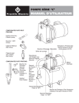
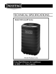
CENTRIFUGAL PUMPS
DDD/DDS SERIES
OWNER'S MANUAL
READ AND FOLLOW SAFETY INSTRUCTIONS
This is the safety alert symbol. When you see
this symbol on your pump or in this manual, look
for one of the following signal words and be alert to the
potential for personal injury:
D A N G E R warns about hazards that will cause
serious personal injury, death or major property damage
if ignored.
W A R N I N G warns about hazards that can cause
serious personal injury, death or major property damage
if ignored.
C A U T I O N warns about hazards that will or can
cause minor personal injury or major property damage if
ignored.
The label NOTICE indicates special instructions, which
are important but not related to hazards.
WA R N I N G
Carefully read and follow all
safety instructions in this
manual and on pump.
Keep safety labels in good
condition.
Hazardous voltage.
Can shock, burn, or
cause death.
Ground pump before
connecting to power
supply. Disconnect
power before working
on pump, motor
or tank.
Replace missing or damaged
safety labels.
Wire motor for correct
voltage. See “Electrical”
section of this manual and
motor nameplate.
Ground motor before
connecting to power supply.
Meet National Electrical Code, Canadian Electrical
Code, and local codes for all wiring.
Follow wiring instructions in this manual when
connecting motor to power lines.
BEFORE INSTALLING PUMP, BE SURE TO READ
THIS OWNER’S MANUAL CAREFULLY.
CAUTION
Mechanical shaft seals do not run dry.
Fill pump with water before starting or pump will be
damaged. The motor on this pump is guaranteed by
the manufacturer and in event of failure it must be
returned to an authorized service station for repairs.
Motor warranty is void if repairs aren’t made by an
authorized repair station.
INSTALLATION
Suction Piping
The pump should be installed as close as possible to
the source of water in order to minimize the length of
suction piping. The suction pipe should never be smaller
in diameter than the suction opening of the pump. It
must be free of all leaks, and should slope continuously
upward from the water source to the pump, with no high
spots, which can trap air. A foot valve must be used to
maintain the prime.
General Piping Instructions
In order to avoid strain on the pump, both the suction
and discharge piping should be properly supported,
and a pipe wrench should be put on the suction and
discharge bosses when installing pipes in them.
Electrical Connections
Remove the end cover (canopy) from the motor, and
using the diagram on top of the motor, make sure it is
connected for the correct voltage.
The motors on “DD” Series pumps are designed to be
used with either 115 or 230 volt supply by changing
connections as shown on the diagram.
CAUTION
Connecting the motor to the wrong
voltage can cause serious damage.
“Table 2” lists branch fuse size ratings and
recommended supply wire for each pump.
Figure 1
Grounding the motor
Make sure that the green lead wire is securely
connected to the green ground terminal screw on
the motor terminal board, “Fig. 1”. This wire must be
connected to the electrical system ground (provided by
the power company) or to another adequate ground.
CAUTION
If any type of wrench must be used on the impeller, be
sure to protect the impeller surfaces by putting a shop
cloth or other protection between the wrench and the
impeller.
Terminal
Board
Capacitor
Ground
Screw
Failure to ground the pump properly
can result in serious or fatal injury.
Typical Discharge Plumbing Options
Vertical Discharge
4. Remove the rotating part of the seal by first removing
the square rubber drive ring (Figure 2) with a small
screwdriver or knife blade. The remainder of the
rotating portion is then loose and may be removed
easily.
Gate Valve
Tee
Discharge Pipe
Base
Suction Pipe
Figure 2
Foot Valve
Horizontal Discharge
Impeller
Gate Valve
Priming Plug
Face of
Sealing Washer
Impeller Hub
Discharge Pipe
Union
Tee
Base
Suction Pipe
Foot Valve
Priming the Pump
Fill the pump and suction piping completely with water
before starting. Never operate the pump without water
in it. The mechanical shaft seal and impeller can be
damaged if run dry. If the pump does not deliver water
in 20 - 30 seconds, some air may be trapped. Stop the
pump, refill with water, and start again.
Shaft Shoulder
Rubber
Drive Ring
5. Remove the seal plate, which is now free. Push
the seal seat out of the seal plate from the back
side. Clean the cavity, from which the seal seat was
removed. Also clean the motor shaft.
6. Replace the seal plate on the motor.
SERVICE THE PUMP
1. Remove the motor from the pump case.
2. Take off the motor end cover (canopy).
3. Remove the impeller from the motor. To keep the
motor shaft from turning while unscrewing the
impeller, hold shaft by inserting a 7/16” (11.1 mm)
open-end wrench at the 7 o’clock position of the
switch end of the motor, as shown in Figure1. The
motor shaft has flat surfaces at that point.
7. Dip the seal seat in a soap solution or clear water for
lubrication and install in the seal cavity. Press firmly in
place with fingers, If it cannot be positioned with the
fingers, put the cardboard washer (furnished with the
seal) on the seal face and press the seat in place with
a piece of pipe or other tool, as shown in (Figure 3).
Remove the cardboard washer and clean the polished
seal surface with a soft cloth. Be very careful not to
damage or scratch the surface.
1
8. Make sure the shaft is clean.
TROUBLESHOOTING
9. Clean the face of the rotating part of the seal with a
soft cloth. Dip the assembly in a soap solution or clear
water and push onto the shaft, with the sealing face
first, until the square rubber drive ring is completely on
the shaft shoulder.
1. PUMP WON’T DELIVER ANY WATER
10. Screw the impeller on the shaft until its hub is against
the shaft shoulder. This automatically positions all
seal parts properly.
2. LOSS OF PRIME
11. Replace the motor on the case and base.
Review priming instructions. Make sure the pump and
suction line are full of water.
a) Check the suction line and foot valve for leaks. The
entire suction side of the system must be totally
air tight.
b) Make sure the water level hasn’t dropped enough
to uncover the suction inlet. Sufficient pipe would
be used to prevent this from happening.
Figure 3
3. LOW FLOW OR PRESSURE
Polished surface
or seat
a) Check suction piping for leaks.
b) Check the impeller for clogging. Remove all foreign
material if it is clogged.
Pipe or Tool
Cardboard
Washer
4. NOISE
a) Make sure pump and piping are supported.
b) Make sure suction lift does not exceed 20 ft.(6mm)
c) Check disch. piping for excessive bends or elbows.
d) Check motor bearing for damage.
Table 2 - Electrical Information
HP
1/2
3/4
1
1-1/2
2
2-1/2
Voltage
Branch
Max. Loads
Amperes
Fuse
Rating
Amperes
Maximum Length of Cable Size Shown
50’
100’
200’
300’
400’
500’
115
8.6
15
14
14
10
8
8
8
230
4.3
15
14
14
14
14
14
12
115
13.2
20
12
12
8
6
6
4
230
6.6
15
14
14
14
12
12
10
115
16.2
25
12
10
8
6
4
2
230
8.1
15
14
14
14
12
10
10
115
20.8
30
10
10
8
6
4
2
230
10.4
15
14
14
12
12
10
8
115
21
30
10
10
6
6
4
2
230
10.5
15
14
14
12
12
10
8
115
23
35
10
8
6
4
2
2
230
11.2
15
14
14
12
12
10
8
2
PARTS FOR MODELS
DDD/DDS SERIES- END SUCTION
CENTRIFUGAL PUMPS
14
9
#5 Impeller Kit
2
#6 Case Kit
3
5
4
8
12
13
11
#7
Base Kit
Figure No.
2
3
4
5
5
6
7
9 & 13
11
12
Part No. Cast Iron
Part No. Stainless Steel
Description
11-0063-01-R
Seal Plate Cast Iron #11293 for DDD, RCFC
Seal Plate Stainless Steel for DDS
47-0258-53-02PK
Square-Ring Kit 6 x 1/8 x 1/8 (2 per kit)
11-1498-04-R
47-0258-53-02PK
10-0002-06
Mechanical Seal 5/8 for DDD, RCFC Models
10-1436-18
Mechanical Seal 5/8 Viton for DDS Models
All Impeller Kits include: impeller, sq.-ring, mech. seal, wear-ring, & fasteners.-Fig. #’s. 3,4,5,12,13
05-3886-08-K
05-3886-16-K
1/2HP Impeller Kit 4.605 dia. #11375
05-3887-07-K
05-3887-15-K
3/4HP Impeller Kit 5.0 dia. #11376
05-3888-06-K
05-3888-14-K
1HP Impeller Kit 5.25 dia. #11377
05-3889-05-K
05-3889-13-K
1.5HP Impeller Kit 5.315 dia. #11378
05-3890-02-K
2HP Impeller Kit 5.65 dia. #11338
05-3891-01-K
2.5HP Impeller Kit 5.95 dia. #11379
Impellers for Units with Three-Phase Motors
05-9646-05-R
05-9646-05-R
1/2HP Impeller 4.605 dia. #11375
05-9650-00-R
05-9650-00-R
3/4HP Impeller 5.0 dia. #11376
05-9652-50-R
05-9652-50-R
1HP Impeller 5.25 dia. #11377
05-9653-15-R
05-9653-15-R
1.5HP Impeller 5.315 dia. #11378
05-9656-50-R
05-9656-50-R
2HP Impeller 5.65 dia. #11338
03-0850-08-R
03-0850-17-R
Case Assembly Kit #11337 w/ plugs #11 for 1/2HP thru 1.5HP
03-0851-07-R
Case Assembly Kit #11338 w/ plugs #11 for 2HP
03-0852-06-R
Case Assembly Kit #11338 w/ plugs #11 for 2.5HP
12-1057-06-R
12-1057-06-R
Base Assembly Kit w/ motor pad #8 for 48 frame mtr.
12-1060-03-K
12-1060-03-K
Base Assembly Kit w/ motor pad #8 for 56 frame mtr.
14-4434-02-K
14-4434-02-K
*Fastener Kit
31-0059-11-06PK
31-0059-11-06PK
Plug Kit 1/4” Galv. (6 per kit)
08-0845-19-06PK
08-0845-19-06PK
Wear-Ring Kit (6 per kit)
13
14-4353-09
14-4354-08
14-4353-09
14-4354-08
Capscrew 1/4-20 x 1-3/16 LG LH Hx. / Wash. for 2HP 3 Ph.
Capscrew 1/4-20 x 7/8 LG LH Hx. / Wash. for 1/2 thru 1.5HP 3 Ph.
14
Motor
Motor
See Motor Selection Page
*Fastener Kit #14443402-K includes the following:
4 each 3/8-16 x 1-1/8 PL Hex Capscrews #9
1 each 1/4-20 x 1-3/16 Hex Wash-Capscrews for 1/2HP thru 1.5HP 3Ph. #13
1 each 1/4-20 x 1-3/6 Hex Wash-Capscrews for 2HP 3Ph. #13
3
U.S. LIMITED WARRANTY*
Franklin Pump Systems, Inc.
Franklin Pump Systems, Inc. warrants its new products to be free of defects in material and workmanship for a
period of 1 year from date of installation or 2 years from date of manufacture, whichever comes first, WHEN installed in
a domestic water systems application and pumping potable water only. Warranty does not cover applications pumping
saltwater or other corrosive liquids. Consult and adhere to local codes for all applications. Franklin Pump Systems, Inc.
also provides additional warranty coverage on specific products as specified herein.
Franklin Pump Systems’ warranty obligation with regard to equipment not of its own manufacture is limited to the
warranty actually extended to Franklin Pump Systems by its suppliers.
This warranty extends only to the original retail purchaser and only during the time in which the original retail
purchaser occupies the site where the product was originally installed.
Requests for service under this warranty shall be made by contacting the installing Franklin Pump Systems
dealer (point of purchase) as soon as possible after the discovery of any alleged defect. Franklin Pump Systems will
subsequently take corrective action as promptly as reasonably possible.
Franklin Pump Systems at its discretion may replace or repair any product that fails under this warranty after
inspection by an authorized company representative or after Franklin Pump Systems has received the product at our
factory. Replacement or repair cannot be made until after the product is inspected. All charges or expenses for freight
to and from the factory, removal and reinstallation of the product, or installation of a replacement product are the
responsibility of the purchaser.
THIS WARRANTY SUPERSEDES ANY WARRANTY NOT DATED OR BEARING AN EARLIER DATE. ANY
IMPLIED WARRANTIES WHICH THE PURCHASER MAY HAVE, INCLUDING MERCHANT ABILITY AND FITNESS
FOR A PARTICULAR PURPOSE, SHALL NOT EXTEND BEYOND THE APPLICABLE WARRANTY PERIOD. Some
states do not allow limitations on how long an implied warranty lasts, so the above limitation may not apply
to you. IN NO EVENT SHALL FRANKLIN PUMP SYSTEMS BE LIABLE FOR INCIDENTAL OR CONSEQUENTIAL
DAMAGES. Some states do not allow the exclusion or limitation of incidental or consequential damages, so
the above may not apply to you.
This warranty does not apply to any product which has been subjected to negligence, alteration, accident, abuse,
misuse, improper installation, vandalism, civil disturbances, or acts of God. The only warranties authorized by Franklin
Pump Systems are those set forth herein. Franklin Pump Systems does not authorize other persons to extend any
warranties with respect to its products, nor will Franklin Pump Systems assume liability for any unauthorized warranties
made in connection with the sale of its products.
THIS WARRANTY GIVES YOU SPECIFIC LEGAL RIGHTS, AND YOU MAY ALSO HAVE OTHER RIGHTS WHICH
MAY VARY FROM STATE TO STATE.
* Contact Franklin Pump Systems, Inc. Export Division for International Warranty.
12401 Interstate 30 • P.O. Box 8903
Little Rock, AR 72219
E1381
3/06
4