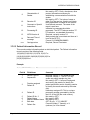
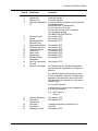
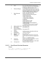
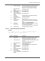
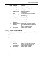
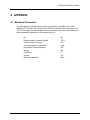
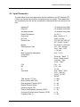
1
OPTI R ™ Blood Gas Analyzer Interface Specifications INTERFACE SPECIFICATIONS INTERFACE SPECIFIATIONS REVISION LOG (Please record any changes made to this manual) Revision Number A B C Release Date April 2007 05 Feb 09 13JUL10 Approved By Description Initial release per CO 070166 Updated per CO 090030 Updated per PCR100206 Changed baud rate to 57600. Updated establishment phase in section 3.2.2.1. Copyright © 2007-2009, OPTI Medical Inc. All rights reserved. Unless otherwise noted, the contents of this document may not be reproduced, transmitted, transcribed, translated, stored in a retrieval system or translated into any language in any form without the written permission of OPTI Medical Inc. While every effort is made to ensure its correctness, OPTI Medical Inc. assumes no responsibility for errors or omissions, which may occur in this document. This document is subject to change without notice. Made in U.S.A. OPTI is a trademark or registered trademark of OPTI Medical Systems, Inc. in the United States and/or other countries. OPTI Medical Systems 4Inc. 235 Hembree Park Drive Roswell, GA 30076 USA www.optimedical.com PD7061 REV C Page 1 of 45 INTERFACE SPECIFICATIONS Table of Contents 1 Preface .............................................................................................................. 3 2 Overview of Interface Hardware for Instrument to Computer Communications ........................................................................................................... 4 2.1 RS-232 Serial Port ............................................................................................. 4 2.1.1 2.1.2 2.1.3 2.1.4 2.2 RS-232 Communication Port Hardware Settings ............................................. 4 RS-232 Pinouts ................................................................................................ 4 Establishing Connections ................................................................................. 5 Standards ......................................................................................................... 5 Ethernet Port ...................................................................................................... 5 2.2.1 Establishing Connections ................................................................................. 5 2.2.2 Standards ......................................................................................................... 5 3 Overview of Communications Protocols for Instrument to Computer Communications ........................................................................................................... 6 3.1 3.2 ASCII Protocol .................................................................................................... 6 ASTM 1394 Protocol .......................................................................................... 6 3.2.1 3.2.2 3.2.3 3.2.4 3.2.5 3.2.6 Control Characters ........................................................................................... 6 Communication Phases ................................................................................... 6 Error Recovery ................................................................................................. 9 Time-outs ......................................................................................................... 9 State Diagram ................................................................................................ 10 Data Examples for ASTM ............................................................................... 23 4 APPENDIX ....................................................................................................... 42 4.1 4.2 4.3 4.4 4.5 Measured Parameters ...................................................................................... 42 Input Parameters .............................................................................................. 43 Calculated Parameters ..................................................................................... 44 Sample Types .................................................................................................. 45 Blood Types ..................................................................................................... 45 Page 2 of 45 INTERFACE SPECIFICATIONS 1 Preface This Interface Specification applies to OPTI Medical OPTI R. This document, along with your OPTI Medical OPTI R Operator's Manual will help guide you through interfacing the OPTI Medical OPTI R to your laboratory data manager or LIS/HIS system. Your OPTI Medical R has an RS232 serial port and a 10baseT Ethernet port as alternative digital communications interfaces. Communication through these ports is configurable (depending on port) for ASCII, ASTM, and Mobile-ASTM protocols. Consult your OPTI Medical OPTI R Operator’s Manual, Section 3.3.2.8, for details on configuring your analyzer to suit your particular laboratory's needs. ASCII Format - Data in easy to read OPTI Medical custom format. The OPTI Medical OPTI R exports a data string identical to the internal printer output. ASTM Format - Complies with ASTM standard 1394-97 with handshaking and data formatting. ASTM format is recommended for use with stationary RS232 operation, where the OPTI Medical OPTI R is always in communication with the host system. Page 3 of 45 INTERFACE SPECIFICATIONS 2 Overview of Interface Hardware for Instrument to Computer Communications 2.1 RS-232 Serial Port The OPTI R includes a standard 9-pin female RS-232 serial port for direct-to-computer communications. 2.1.1 RS-232 Communication Port Hardware Settings Table 1 Setting Default Start bit Data bit Parity Stop bit Baud Rate 1 8 None 1 57600 2.1.2 RS-232 Pinouts The following pin connection configurations should be utilized for PC to LIS/HIS connections: Rear View of OPTI Medical OPTI R Page 4 of 45 Pin Number Designation Pin 1 Pin 2 Pin 3 Pin 4 Pin 5 Pin 6 Pin 7 Pin 8 Pin 9 No Connection RxD TxD DTR GND DSR No Connection CTS No Connection Host Transmit Receive Signal Ground INTERFACE SPECIFICATIONS 2.1.3 Establishing Connections The RS-232 interface is of an “always-on” nature. So long as the instrument is on, a connection with the host computer is presumed present. 2.1.4 Standards Further details of this interface are available in ASTM standard E1381-02. 2.2 Ethernet Port The OPTI R includes a standard RJ45 10baseT Ethernet port for networked computer communications. 2.2.1 Establishing Connections The instrument’s MAC address, IP address, IP port, and target computer’s IP address & port are software configurable. Consult the instrument’s user manual for more details on how these configuration settings are implemented. Shortly after powerup, the instrument will persistently attempt to establish a socket connection with the target computer’s IP address and port as configured. 2.2.2 Standards Further details of this interface are available in ASTM standard E1381-02. Page 5 of 45 INTERFACE SPECIFICATIONS 3 Overview of Communications Protocols for Instrument to Computer Communications 3.1 ASCII Protocol The ASCII protocol is a straightforward duplication of the content produced via the instrument’s printer. 3.2 ASTM 1394 Protocol 3.2.1 Control Characters Control characters that are used for ASTM communications: Table 2 ASCII Decimal Hex Control Character Comment STX 2 0x2 ^B Start of TeXt ETX 3 0x3 ^C End of TeXt EOT 4 0x4 ^D End Of Transmission ENQ 5 0x5 ^E ENQuiry ACK 6 0x6 ^F ACKnowledge LF 10 0xA ^J Line Feed CR 13 0xD ^M Carriage Return NAK 21 0x15 ^U Negative AcKnowledge ETB 23 0x17 ^W End of Trans. Block 3.2.2 Communication Phases There are three (3) distinct phases to each communication session. They are the Establishment phase, the Transfer phase, and the Termination phase. Each of these phases will be discussed in the following paragraphs. 3.2.2.1 Establishment Phase When the OPTI Medical OPTI R is ready to send data, it transmits an ENQ character. After the ENQ is sent, instrument waits for 15 seconds for a response from the host. If there is no response from the host within 15 seconds, the instrument terminates the establishment phase and sends EOT. Host < ACK or NAK. If an ACK character is received from the host, the Establishment phase is successful, and the OPTI R will go immediately to the transfer phase. If a NAK character is received from the host, the instrument waits 10 seconds and then resends the ENQ to establish communications and repeat this loop until an ACK is received. This ends the establishment phase of the communication session. Page 6 of 45 INTERFACE SPECIFICATIONS 3.2.2.2 Transfer Phase The transfer phase is when the sender transmits the message to the receiver. The transfer continues until all messages have been sent. Sender> STX FN Data ETB or ETX CR LF Receiver< ACK 3.2.2.3 Explanation of fields STX Start of text: ASCII decimal 2. This control character identifies the starting point of the data that is being sent from the analyzer. This character must accompany all data transmissions. FN Frame number: A single digit field that distinguishes between new and retransmitted frames. Legal characters are ASCII `0' to `7'. The frame number must start at 1 with the first frame of the transfer phase. The frame number is incremented by one for every new frame transmitted. After `7', the frame number rolls over to `0', and continues in this fashion. Data Data is the instrument information, demographic information, and actual results (measured or calculated) from the instrument. The length of the fields should accommodate the result name, actual result, result unit, and any instrument-generated alarms for that result. ETB or ETX The ETB character is End of Transmission Block and is only sent when there are multiple frames. When a message contains over 240 characters it must be broken into two or more frames. Each frame other than the final must be terminated with an ETB (end of transmission block), CS (checksum), CR (carriage return) and LF (line feed). The final frame is terminated with an ETX (end of text), CS (checksum), CR (carriage return) and LF (line feed). The structure is below: STX FN data ETB CS CR LF Ü Intermediate frame(s) STX FN data ETX CS CR LF Ü End frame Page 7 of 45 INTERFACE SPECIFICATIONS 3.2.2.4 Termination Phase The termination phase returns the communication link to the clear or neutral state. The sender notifies the receiver that all messages have been sent. Sender___________ Receiver EOT No response The termination phase is a sequence of conditions that will cause communication between the devices to cease. The termination phase is entered when the sender has no more data to transmit. Termination is accomplished by transmitting an EOT. When the EOT is sent, no acknowledgment is needed, do not expect an ACK. The receiver, upon receiving EOT, considers the communication to have ended and sends no further data or acknowledgments. 3.2.2.5 Special Characters & Fields Each phase of communication also contains special characters and fields, as described below: 3.2.2.5.1 Checksums The CS (checksum) is used for checking data integrity. The checksum is computed by adding the binary values of the characters in the message, keeping the least significant 8 bits of the result. The checksum is initialized to zero with the STX character. The first character used in computing the checksum is the frame number. Each character in the message text is added to the checksum (modulo 256). The calculation of the checksum does not include the STX, the checksum characters, or the trailing CR and LF (the ETX/ETB is included in the calculation). The checksum is converted to two ASCII characters of the hexadecimal representation. The two characters are transmitted as the checksum, with the most significant character first (C1). For example, a checksum of 122 can be represented as 0x7A (0x stands for hexadecimal). The checksum is transmitted as the ASCII character `7' followed by the character `A'. The CR (carriage return) and LF (line feed) combination is used as the end termination characters of the message text. 3.2.2.5.2 Acknowledgments After each frame is sent, the sender must wait up to 15 seconds for a reply. The receiver shall transmit one of three replies: ACK (Decimal 06) The ACK reply signifies the last frame was successful and it is OK to send another frame. The sender increments the frame number and sends a new frame or terminates the transmission (see termination phase). NAK (Decimal 21) The NAK reply signifies the last frame was not received successfully and the receiver is prepared to receive the frame again. The sender will re-transmit the last frame with the same frame number. EOT (Decimal 04) Page 8 of 45 INTERFACE SPECIFICATIONS The EOT reply signifies the last frame was received successfully and the receiver is prepared to receive another frame, but is requesting the sender stop transmitting data. See interrupts below. 3.2.2.5.3 Interrupts During the transfer phase, if the receiver responds to a frame with an EOT in place of an ACK, the sender must interpret this as an interrupt request. The EOT signifies the last frame was successful, but the receiver is requesting the sender stop transmitting. If the sender chooses to ignore the EOT, the receiver must re-send the EOT for the interrupt to remain valid. If the sender chooses to honor the interrupt, the sender must enter the termination phase (See termination phase below). The sender must not enter the establishment phase for at least 15 seconds or until the receiver has finished a message cycle (establishment, transfer, termination). 3.2.3 Error Recovery The receiver checks every frame for valid data. To check data, the receiver calculates the checksum on the received data and compares this calculated checksum to the checksum that was transmitted by the sender and sent with the data stream. If the checksums match, the data is valid; if the checksums do not match the data is not valid and the receiver must send a NAK. Upon receiving the NAK, the sender re-transmits the last frame with the same frame number. A frame should be rejected for the following errors: Any character errors are detected (parity error, framing error, etc.) The calculated frame checksum does not match the checksum in the received frame. The frame number is not the same as the last accepted frame or one higher. Upon receiving a NAK, or any character except ACK or EOT, the sender increments a retransmit counter and retransmits the same frame (with the same frame number). If the counter shows the frame was not accepted after six times the sender must abort the message and proceed immediately to the termination phase. 3.2.4 Time-outs If the reply after sending an ENQ is not received within 15 seconds, the sender enters the termination phase. If the receiver detects contention and no ENQ is received within 20 seconds, the receiver regards the data link to be in the neutral state. If the sender receives no reply within 15 seconds after transmitting the last character of a frame, it aborts the message by entering the termination phase. During the transfer phase, the receiver sets a timer when first entering the transfer phase or when replying to a frame. If a frame or an EOT is not received within 30 seconds, the receiver discards the incomplete message and regards the line to be in the neutral state. The receiver can delay its reply for up to 15 seconds. Longer delays cause the sender to abort the message. Page 9 of 45 INTERFACE SPECIFICATIONS 3.2.5 State Diagram Receiving Device Page 10 of 45 Sending Device INTERFACE SPECIFICATIONS 3.2.5.1 Restricted Characters None of the ten transmission control characters, the line feed control, or the four device control characters may appear in message text. The following characters are not permitted to appear in the message text: Table 3 Illegal Message Text Characters SOH LF ETB STX ACK DC1 ETX DLE DC2 EOT NAK DC3 ENQ SYN DC4 3.2.5.2 Message Structure A message is a group of records that begins with a Header record and ends with a Terminator record, with one or more other types of records between the Header and Terminator. Each record has a number of fields, separated by the vertical bar | character. Below is a description of the records and the fields within each record. Table 4 ID Record Types ID Record Types H P O R C HeaderRecord PatientRecord Test Order Record Result Record Comment Record Q S M L Request Record Record N/A Scientific Record Record N/A Manufacturer Record N/A Message Terminator Note: Record type ID is not case sensitive, however it is suggested to always use upper case. 3.2.5.2.1 Delimiters Delimiters are ASCII characters used to separate fields within a record and to separate sub-components within fields. Below is a description of the delimiters and how they should be used: Table 5 Page 11 of 45 Character Name Used As: | \ ^ & CR Vertical bar Backslash Caret Ampersand Carriage return Field delimiter Repeat delimiter Component delimiter Escape delimiter Record delimiter INTERFACE SPECIFICATIONS Field delimiter Separates adjacent fields | field | Repeat delimiter Must be defined in the message header and is used to separate various numbers of descriptors for the same field. For example, a patient has two phone numbers. |5555555\444-4444| Component delimiter Used to separate data elements within a field that has a hierarchical or qualifier nature. For example, the components of an address field would be separated. |street^city^state^zip| Escape delimiter The escape delimiter is used to identify special case operations within a text field. For example, if text were supposed to be highlighted, the field would be |&H&DoctorsName&N&| the &H& signifies begin highlighting text and the &N& signifies start normal text. The application of the escape delimiter is optional and may be ignored, however all applications must accept the escape delimiter and use it to correctly parse fields within the record. 3.2.5.3 Null values All fields are position dependent and are obtained by counting field delimiters by their position starting from the front of the record. This means if a field is null (no information available) the field delimiters must be included in the record. This ensures each field can be identified by counting n+1 delimiters. Trailing null fields do NOT need to be included. Delimiters are not needed after the last field containing data. Null values may be sent for the following reasons: The value is not known The sender knows the field is irrelevant to the receiving system. The value has not changed since the last transmission A field containing only a pair of double quotes "" should be treated by the receiving system as an instruction to delete any existing contents of that field. Note: The receiving system may ignore any field it does not require. However, fields must always be transmitted in the positional order specified. Page 12 of 45 INTERFACE SPECIFICATIONS 3.2.5.4 Header Record This record must always be the first record in a message transmission. This record contains information about the sender and receiver, instruments, and computer system whose records are being exchanged. It also identifies the delimiter characters. The minimum information that must be sent in a Header record is: 1H|\^&<cr>4 The 1 corresponds to the Frame Number. The H corresponds to the record type, H=Header. The `|' (vertical bar) is used as a field delimiter. The `\' (backslash) is a repeat delimiter. The `^' (caret) is a field component delimiter. The `&' (ampersand) is an Escape delimiter. The <cr> is identified as a Carriage Return (ASCII decimal 13). The Carriage Return signifies the end of the record. The entire header record consists of the following fields: 1|2|3|4|5|6|7|8|9|10|11|12|13|14<cr> Examples: P|\^&|||OPTI Medical OPTI R^1.01.0001^4850|||||| Meas|P|2.2| 20050108132841<cr> Field # 1 Page 13 of 45 Field Name Record Type ID 2 Delimiter definitions 3 Message Control ID 4 Access Password 5 Sender Name or ID 6 Sender Street Address 7 Reserved Field 8 Sender Telephone # Comment Required. Always `H' for header records. Required, see table 5, and in the format shown in above example the first character is the field delimiter, the second is the repeat delimiter, the third is the component, and the fourth is the escape character. Not used by OPTI. Used in network systems that have defined acknowledgement protocols. Not used by OPTI. This is a level security/access password as mutually agreed upon by sender and receiver. Name of manufacturer/instrument,<version string> and <serial number>. E.g. OPTI Medical OPTI R^1.01.0001^4850 Not used by OPTI. Text containing street address of sender. Not used by OPTI. Reserved for future use, not currently specified. Not used by OPTI. Identifies telephone number for voice communication with the sender. INTERFACE SPECIFICATIONS 9 Characteristic of Sender 10 Receiver ID 11 Comment or Special Instructions 12 Processing ID 13 ASTM Version # 14 Date and Time of message <cr> Carriage return Not used by OPTI. Parity, checksums, other protocol information necessary for establishing a communication link with the sender. Not used by OPTI. Text value of name or other ID of the receiver. Used to verify data being transmitted is indeed for the receiver. User-defined comment. The name of the report is sent here. Indicates how message should be processed: The OPTI R always sends a "P". P-Production, use standard processing. Required, currently version 2.2 Always sends the current date and time as it is set in the OPTI R. Format=YYYYMMDDHHMMSS Required, Record Terminator 3.2.5.5 Patient Information Record This record contains information about an individual patient. The Patient Information record consists of the following fields: 1|2|3|4|5|6|7| 8|9|10|11|12|13|14| 15|16|17 |18|19|20|21|22|23 |24|25|26|27|28|29| 30|31 |32|33|33|34|35<cr> Example: P|1||321225432||||| M|||||||||||||||||||||||||| <cr> Field # 1 Page 14 of 45 Field Name Record Type ID 2 Sequence# 3 Practice assigned Patient ID 4 Patient ID 5 6 7 8 Patient ID No. 3 Patient Name Mother's Maiden Name Birth date 9 Patient Sex Comment Required, Always `P' for patient records. Required, Always `1'. The OPTI R only sends one patient sample at a time. Not used by OPTI. A unique ID assigned and used by the practice to identify the patient and his/her results. Used by practice to identify the results returned by the tester (lab). Laboratory assigned ID. This is a unique processing number generated by the lab, the LIS, or the HIS (bar code number). Not used by OPTI. Not used by OPTI. Not used by OPTI. OPTI R only: “YYYY-MM-DD” Format M (male), F (female), or U (unknown) or if not entered. INTERFACE SPECIFICATIONS 10 11 12 13 14 15 16 17 18 19 20 21 22 23 24 Patient Race Patient Address Reserved Patient Telephone # Attending Physician Special field 1 Special field 2 Patient Height Patient Weight Known or suspected diagnosis Patient active medications Patient diet Practice field 1 Practice field 2 Admission and discharge dates, separated by a ^ Not used by OPTI. Not used by OPTI. Not used by OPTI. Not used by OPTI. Not used by OPTI. Not used by OPTI. Not used by OPTI. Not used by OPTI. Not used by OPTI. Not used by OPTI. Not used by OPTI. Not used by OPTI. Not used by OPTI. Not used by OPTI. Not used by OPTI. 25 Admission status 26 27 28 29 30 31 Location DRG or AVG DRG or AVG #2 Patient Religion Marital Status Isolation Status Not used by OPTI. OP-outpatient, PA-pre-admit, IP-inpatient, ER-emergency room Not used by OPTI. Not used by OPTI. Not used by OPTI. Not used by OPTI. Not used by OPTI. Not used by OPTI. 32 Language Not used by OPTI. 33 Hospital Service Not used by OPTI. 34 Hospital Institution Not used by OPTI. 35 Dosage Category Not used by OPTI. Carriage return Required, Record Terminator <cr> 3.2.5.6 Test Order Record The order record defines the particular type of tests run or performed for each specimen and is transmitted back to the host computer system as part of the results. The Test Order record consists of the following fields: 1|2|3|4|5|6|7|8|9|10|11|12|13|14|15|16|17|18|19|20|21|22|23|24|25|26|27|28|29|30|31<c r> Example: O|1||MEASUREMENT^456||||||||||||Blood^Arterial|||||||20050531132 840||||||||<cr> Page 15 of 45 INTERFACE SPECIFICATIONS Field # 1 2 3 4 Field Name Record Type ID Sequence# Specimen ID Instrument Specimen ID 5 6 7 Universal test ID Priority Requested/Order Date and Time Spec imen collection Collection end time Collection volume Collector ID Action code Danger code Relevant clinical information Date/Time specimen received Specimen descriptor 8 9 10 11 12 13 14 15 16 Comment Required. Always `O' for order records Required, Always `1' Accession Number A unique identifier assigned by the instrument. For Patient records: MEASUREMENT^<sequence #> For QC records: QC^<Lot#> For Auto QC records: AQC^<packlot#> For Calibration records: CALIBRATION^SYSTEM CAL Not used by OPTI. Not used by OPTI. Not used by OPTI. Not used by OPTI. Not used by OPTI. Not used by OPTI. Not used by OPTI. Not used by OPTI. Not used by OPTI. Not used by OPTI. Not used by OPTI. For Patient records: Includes the specimen type and source, separated by a component delimiter. E.g.: Blood^Arterial as selected by the user, the list of possible selections is located in the appendix of this document and is also in the Operator's Manual, Appendix A; Input values; Sample Type. For Liquid QCrecords: Includes the QC type and level, separated by a component delimiter. E.g.: OPTI-check^1 Other^1 17 18 19 20 21 Page 16 of 45 Ordering Physician Physician's Telephone # User field 1 User field 2 Laboratory Field 1 Not used by OPTI. Not used by OPTI. Cassette Lot Number (Patient & LQC); Pass/Fail Not used by OPTI. INTERFACE SPECIFICATIONS 22 23 Laboratory Field 2 Date/time results reported or Last instrument 24 Instrument Charge to Computer System Instrument Section ID 25 26 27 28 29 30 31 <cr> Report Types Reserved Field Location or Ward Nosocomial Infection Flag Specimen Service Specimen Institution Carriage return Not used by OPTI. Sends the date and time as it is set in the OPTI when the completed the results or they were last Modified modified. Format: YYYYMMDDHHMMSS Not used by OPTI. Not used by OPTI. OP-outpatient, PA-pre-admit, IP-inpatient, ER-emergency room Not used by OPTI. Not used by OPTI. Not used by OPTI. Not used by OPTI. Not used by OPTI. Not used by OPTI. Required, Record Terminator 3.2.5.7 Result Record The Result Record is used to send actual patient results that were performed on an instrument. The Result Record consists of the following fields: 1|2|3|4|5|6|7| 8|9|10|11|12|13|14<cr> 3.2.5.7.1 Result Record Measured Parameters Example: R|2|^^^PCO2^M^^|24.1|mmHg|30.0 to 50.0|L||||OPID1234567|| 20050531132803|OPTI Medical OPTI R^1.01.0001^4850<cr> Field # 1 2 Page 17 of 45 Field Name Record Type ID Sequence# 3 Universal Test ID 4 Data measurement Comment Required. Always `R' for result records. Required, sequentially generated number identifying the number of each record. ^^^Sensor Name^how value was derived, M Measured^. Note: A "t" is inserted after the <Sensor Name> if the result was temperature corrected. E.g.^^^<Sensor Name>t^M^^ Results from instrument XX.X XX.X=value (number or value of significant digits depends on analyte and instrument setup as described in the Operator's Manual section 3.3.2.3 INTERFACE SPECIFICATIONS 5 Units 6 Reference Ranges 7 Result Abnormal Flags 8 9 10 Nature of abnormality Result Status Date of Change in Instrument Normative Values Operator Identification Date/Time Test Started Date/Time test Completed 11 12 13 14 <cr> 3.2.5.7.2 Instrument Identification Carriage return SI or Conventional Units of measurement. Depends on instrument setup as described in the Operator's Manual section 3.3.2.3 Current Ranges for the particular analyte as setup in setup; patient info; limits. In the case of an LQC sample the field contains the LQC Pass/Fail ranges as set up in Setup - QC Control. See Operator's Manual 4.5.1.2 Dilution information, Errors, etc. Characters identifying these flags are: L Below reference low H Above reference high < Off low scale of instrument > Off high scale of instrument A Abnormal O SRC failed due to noise D SRC failed due to drift ? Inserted if sensor did not endpoint or calibrate correctly * - Inserted in Patient or Auto QC output if parameter failed user limits for Auto QC. Not used by OPTI. Not used by OPTI. Not used by OPTI. Identifies operator who performed the test (instrument operator). Not used by OPTI. Sends the date and time as it is set in the OPTI R when the instrument completed the test. Format: YYYYMMDDHHMMSS Name of manufacturer/instrument, <version string> and <serial number>. E.g. OPTI Medical OPTI R^1.01.0001^4850 Required, Record Terminator Result Record Calculated Parameters Example: R|1|^^^BE^C^^|3.9|mmol/L||||||654871351||| OPTI Medical OPTI R^1.01.0001^4850<cr> Page 18 of 45 INTERFACE SPECIFICATIONS Field # 1 2 3 Universal Test ID 4 Data measurement or value Units Reference Ranges Result Abnormal Flags Nature of abnormality Result Status Date of Change in Instrument Normative Values Operator Identification 12 Date/Time Test Started Date/Time test Completed Instrument Identification 5 6 7 8 9 10 11 12 13 14 <cr> 3.2.5.7.3 Field Name Record Type ID Sequence# Carriage return Comment Required. Always `R' for result records. Required, sequentially generated number identifying the number of each record. Sensor Name^how value was derived, CCalculated E.g. ^^^<Sensor Name>^C^^ Results from instrument XX.X XX.X=value SI or Conventional Units of measurement Not used by OPTI. Not used by OPTI. Not used by OPTI. Not used by OPTI. Not used by OPTI. Identifies operator who performed the test (instrument operator). Not used by OPTI. Not used by OPTI. Name of manufacturer/instrument, <version string> and <serial number>. E.g. OPTI Medical R R^1.00.0001^4850 Required, Record Terminator Result Record Baro Example: R|1|^^^BARO^M^^|731.2|mmHg||||||654871351||20050531132840| OPTI Medical OPTI R^1.01.0001^4850<cr> Field # 1 2 3 Universal Test ID 4 Data measurement or value Units 5 Page 19 of 45 Field Name Record Type ID Sequence# Comment Required. Always `R' for result records. Required, sequentially generated number identifying the number of each record. ^^^^BARO^how value was derived, M Measured^. E.g. ^^^BARO^M^^ Results from instrument XX.X XX.X=value SI or Conventional Units of measurement INTERFACE SPECIFICATIONS 6 Reference Ranges 7 Result Abnormal Flags Nature of abnormality Result Status Date of Change in Instrument Normative Values Operator Identification 12 Date/Time Test Started Date/Time test Completed 8 9 10 11 12 13 14 <cr> 3.2.5.7.4 Instrument Identification Carriage return Reference ranges of that particular analyte; For more information see the Operator's Manual: 3.3.2.1 Customization - Ranges Not used by OPTI. Not used by OPTI. Not used by OPTI. Not used by OPTI. Identifies operator who performed the test (instrument operator). Not used by OPTI. Sends the date and time as it is set in the OPTI R when the instrument completed the test. Format: YYYYMMDDHHMMSS. Name of manufacturer/instrument, <version string> and <serial number>. E.g. OPTI Medical OPTI R^1.01.0001^4850 Required, Record Terminator Result Record Input Parameters Example: R|1|^^^Temp^S^^|37.0|°C||||||654871351||20050531132840| OPTI Medical OPTI R^1.01.0001^4850<cr> Field # 1 2 3 Universal Test ID 4 Data measurement or value Units Reference Ranges Result Abnormal Flags Nature of abnormality Result Status Date of Change in Instrument Normative Values 5 6 7 8 9 10 Page 20 of 45 Field Name Record Type ID Sequence# Comment Required. Always `R' for result records. Required, sequentially generated number identifying the number of each record. ^^^Input Value Name^how value was derived, S Input^. E.g. ^^^<Input Value Name>^S^^ Results from instrument XX.X XX.X=value SI or Conventional Units of measurement Not used by OPTI Not used by OPTI. Not used by OPTI. Not used by OPTI. Not used by OPTI. INTERFACE SPECIFICATIONS 11 12 13 14 <cr> Operator Identification Date/Time Test Started Date/Time test Completed Instrument Identification Carriage return Identifies operator who performed the test (instrument operator). Not used by OPTI. Sends the date and time as it is set in the OPTI R when the instrument completed the test. Format: YYYYMMDDHHMMSS. Name of manufacturer/instrument, <version string> and <serial number>. E.g. OPTI Medical OPTI R^1.01.0001^4850 Required, Record Terminator 3.2.5.8 Comment Record Comment records may be inserted anywhere except after the message terminator record. Each comment record applies to the first non-comment record preceding it. The comment record consists of the following fields: 1|2|3|4|5<cr> Example: C|1|I| ph under 7.20 (Ref. Lim)^PCO2 over 50 (Ref.Limit)|G<cr> Field # 1 2 Field Name Record Type ID Sequence# 3 Comment Source 4 Comment Text 5 Comment Type <cr> Carriage return Comment Required. Always `C' for comment records Always `1', the OPTI only sends one comment record at a time. Always `I', I Clinical Instrument Sends applicable text; in this case the Sodium result was over the reference limit of the instrument. Always inserts `G' G Generic/Free Text Required, Record Terminator 3.2.5.9 Calibration Record Calibration records are only available when the Mini-Cal feature is turned on. Calibration records are inserted after the test order messages and before the terminator record. The calibration records apply to the test order records preceding them. The calibration record consists of the following fields: 1|2|3|4|5|6|7| 8|9|10|11|12|13<cr> Example: R|1|^^^pH|7.426|||||OK||||20050531132354<cr> Page 21 of 45 INTERFACE SPECIFICATIONS Field # 1 2 3 Universal Test ID 4 Calibration Value 5 6 7 Units Reference Ranges Result Abnormal Flags Nature of abnormality Result Status Date of Change in Instrument Normative Values Operator Identification Date/Time calibration completed 8 9 10 11 12 <cr> 3.2.5.10 Field Name Record Type ID Sequence# Carriage return Comment Required. Always `R' for result records. Required, sequentially generated number identifying the number of each record. ^^^Sensor Name E.g. ^^^<Sensor Name> Results from instrument XX.X XX.X=value SI or Conventional Units of measurement Not used by OPTI Not used by OPTI. Not used by OPTI. Either "OK" or "NO" Not used by OPTI. Not used by OPTI Sends the date and time as it is set in the OPTI R when the instrument completed the test. Format: YYYYMMDDHHMMSS Required, Record Terminator Message Terminator Record This is the last record in the message. A header record may be transmitted after this record to signify the start of another message. The Message terminator record consists of the following fields: 1|2|3|<cr> Example: L|1|N<cr> Field # 1 2 3 <cr> Page 22 of 45 Field Name Record Type ID Sequence# Termination code Carriage return Comment Required. Always `L' for terminator records Always `1'. The OPTI only will send one Message Terminator Record at a time. Always `N' Normal Terminator Required, Record Terminator INTERFACE SPECIFICATIONS 3.2.6 Data Examples for ASTM Legend: Control codes will be enclosed in <xxx>. This is for clarity and example purposes only. The character will be used to show the data stream continues on the next line. It is not in the actual data stream. The <CS> denotes checksum, the modulo 256 checksum should be calculated and inserted in each data stream. 3.2.6.1 Patient Sample OPTI: <ENQ> Receiver: <ACK> OPTI: <STX>1H|\^&|||OPTI Medical OPTI R^1.01.0001^4337||||||Meas|P|2.2| 20050531132840<ETX><CS><CR><LF> Receiver: <ACK> OPTI: <STX>2P|1||PatientID123456||||1979-03-15|M<ETX><CS><CR><LF> Receiver: <ACK> OPTI: <STX>3O|1|AccessionNum|123456789012|MEASUREMENT^3|||||||||||| Blood^Arterial|||219400||||20050531132840<ETX><CS><CR><LF> Receiver: <ACK> OPTI: <STX>4C|1|I|pH over 7.600 (Ref.Lim)|I<ETX><CS><CR><LF> Receiver: <ACK> OPTI: <STX>5R|1|^^^pH^M^^|7.604||7.200 to 7.600|H||||OPID1234567|| 20050531132803|Osmetch OPTI R^1.01.0001^4337<ETX><CS><CR><LF> Receiver: <ACK> Page 23 of 45 INTERFACE SPECIFICATIONS OPTI: <STX>6R|2|^^^PCO2^M^^|34.1|mmHg|30.0 to 50.0|||||OPID1234567|| 20050531132803| OPTI Medical OPTI R^1.01.0001^4337<ETX><CS><CR><LF> Receiver: <ACK> OPTI: <STX>7R|3|^^^PO2^M^^|136.6|mmHg|70.0 to 700.0|||||OPID1234567|| 20050531132803| OPTI Medical OPTI R^1.01.0001^4337<ETX><CS><CR><LF> Receiver: <ACK> OPTI: <STX>0R|4|^^^Na^M^^|140.3|mmol/L|135.0 to 145.0 |||||OPID1234567||20050531132803|OPTI Medical OPTI R ^1.01.0001^4337 <ETX><CS><CR><LF> Receiver: <ACK> OPTI: <STX>1R|5|^^^K^M^^|5.79|mmol/L|3.50 to 5.10|||||OPID1234567|| 20050531132803|OPTI Medical OPTI R^1.01.0001^4337<ETX><CS><CR><LF> Receiver: <ACK> OPTI: <STX>2R|6|^^^iCa^M^^|1.27|mmol/L|1.12 to 1.32|||||OPID1234567|| 20050531132803|OPTI Medical OPTI R^1.01.0001^4337 <ETX><CS><CR><LF> Receiver: <ACK> OPTI: <STX>3R|7|^^^ctHb^M^^|15|g/dL|12.0 to 17.0|||||OPID1234567|| 20050531132803|OPTI Medical OPTI R^1.01.0001^4337<ETX><CS><CR><LF> Receiver: <ACK> OPTI: Page 24 of 45 INTERFACE SPECIFICATIONS <STX>4R|8|^^^SO2^M^^|78|%|90.0 to 100.0|||||OPID1234567|| 20050531132803|OPTI Medical OPTI R^1.01.0001^4337<ETX><CS><CR><LF> Receiver: <ACK> OPTI: <STX>5R|9|^^^BE^C^^|3.6|mmol/L||||||OPID1234567||| OPTI Medical OPTI R^1.01.0001^4337 <ETX><CS><CR><LF> Receiver: <ACK> OPTI: <STX>6R|10|^^^tCO2^C^^|24.1|mmol/L||||||OPID1234567||| OPTI Medical OPTI R^1.01.0001^ 4337<ETX><CS><CR><LF> Receiver: <ACK> OPTI: <STX>7R|11|^^^HCO3^C^^|23.4|mmol/L||||||OPID1234567||| OPTI Medical OPTI R^1.01.0001^ 4337<ETX><CS><CR><LF> Receiver: <ACK> OPTI: <STX>0R|12|^^^Hct(c)^C^^|0.0|%||||||OPID1234567||| OPTI Medical OPTI R^1.01.0001^4337 Receiver: <ACK> OPTI: <STX>1R|13|^^^Baro^M^^|734.3|mmHg||||||OPID1234567|| 20050531132803|OPTI Medical OPTI R^1.01.0001^4337<ETX><CS><CR><LF> Receiver: <ACK> OPTI: <STX>2R|14|^^^AccNum^S^^|OPID123456712|||||||OPID1234567|| 20050531132803|OPTI Medical OPTI R^1.01.0001^4337<ETX><CS><CR><LF> Receiver: <ACK> Page 25 of 45 INTERFACE SPECIFICATIONS OPTI: <STX>3R|15|^^^Temp^S^^|37.0|C||||||OPID1234567||20050531132803| OPTI Medical OPTI R^1.01.0001^4337<ETX><CS><CR><LF> Receiver: <ACK> OPTI: <STX>4R|16|^^^O2 Mode^S^^|Room Air|||||||OPID1234567||20050531132803| OPTI Medical OPTI R^1.01.0001^4337<ETX><CS><CR><LF> Receiver: <ACK> OPTI: <STX>5R|17|^^^Bypass^S^^|On_Pump|||||||OPID1234567|| 20050531132803|OPTI Medical OPTI R^1.01.0001^4337<ETX><CS><CR><LF> Receiver: <ACK> OPTI: <STX>6R|18|^^^FR^S^^|1.00|Lpm||||||OPID1234567||20050531132803| OPTI Medical OPTI R^1.01.0001^4337<ETX><CS><CR><LF> Receiver: <ACK> OPTI: <STX>7R|19|^^^FIO2^S^^|0.21|||||||OPID1234567||20050531132803| OPTI Medical OPTI R^1.01.0001^4337<ETX><CS><CR><LF> Receiver: <ACK> OPTI: <STX>0R|20|^^^SamType^S^^|Art|||||||OPID1234567||20050531132803 |OPTI Medical OPTI R^1.01.0001^4337<ETX><CS><CR><LF> Receiver: <ACK> OPTI: <STX>1R|21|^^^Puncture Site^S^^|LR|||||||OPID1234567|| 20050531132803|OPTI Medical OPTI R^1.01.0001^4337<ETX><CS><CR><LF> Page 26 of 45 INTERFACE SPECIFICATIONS Receiver: <ACK> OPTI: <STX>2R|22|^^^Vent Mode^S^^|SIMV|||||||OPID1234567|| 20050531132803|OPTI Medical OPTI R^1.01.0001^4337<ETX><CS><CR><LF> Receiver: <ACK> OPTI: <STX>3R|23|^^^VT^S^^|1000|mL||||||OPID1234567||20050531132803| OPTI Medical OPTI R^1.01.0001^4337<ETX><CS><CR><LF> Receiver: <ACK> OPTI: <STX>4R|24|^^^VE^S^^|100|L||||||OPID1234567||20050531132803| OPTI Medical OPTI R ^1.01.0001^4337<ETX><CS><CR><LF> Receiver: <ACK> OPTI: <STX>5R|25|^^^PIP^S^^|100|||||||OPID1234567||20050531132803| OPTI Medical OPTI R ^1.01.0001^4337<ETX><CS><CR><LF> Receiver: <ACK> OPTI: <STX>6R|26|^^^Pplat^S^^|1.0|||||||OPID1234567||20050531132803| OPTI Medical OPTI R ^1.01.0001^4337<ETX><CS><CR><LF> Receiver: <ACK> OPTI: <STX>7R|27|^^^PS^S^^|1|||||||OPID1234567||20050531132803| OPTI Medical OPTI R^1.01.0001^4337<ETX><CS><CR><LF> Receiver: <ACK> OPTI: <STX>0R|28|^^^PEEP^S^^|10|||||||OPID1234567||20050531132803| OPTI Medical OPTI R ^1.01.0001^4337<ETX><CS><CR><LF> Receiver: <ACK> Page 27 of 45 INTERFACE SPECIFICATIONS OPTI: <STX>1R|29|^^^CPAP^S^^|10|||||||OPID1234567||20050531132803| OPTI Medical OPTI R ^1.01.0001^4337<ETX><CS><CR><LF> Receiver: <ACK> OPTI: <STX>2R|30|^^^f^S^^|100|bpm||||||OPID1234567||20050531132803| OPTI Medical OPTI R ^1.01.0001^4337<ETX><CS><CR><LF> Receiver: <ACK> OPTI: <STX>3R|31|^^^IE^S^^|1.0:1.0|||||||OPID1234567||20050531132803| OPTI Medical OPTI R^1.01.0001^4337<ETX><CS><CR><LF> Receiver: <ACK> OPTI: <STX>4R|32|^^^BiLevel^S^^|2.0/2.0|||||||OPID1234567|| 20050531132803|OPTI Medical OPTI R^1.01.0001^4337<ETX><CS><CR><LF> Receiver: <ACK> OPTI: <STX>5R|33|^^^HbType^S^^|Adult|||||||OPID1234567||20050531132803 | OPTI Medical OPTI R^1.01.0001^4337<ETX><CS><CR><LF> Receiver: <ACK> OPTI: <STX>6R|34|^^^tHb^S^^|15.0|g/dL||||||OPID1234567||20050531132803 | OPTI Medical OPTI R^1.01.0001^4337<ETX><CS><CR><LF> Receiver: <ACK> OPTI: <STX>7R|35|^^^MCHC^S^^|33.3|%||||||OPID1234567||20050531132803| OPTI Medical OPTI R^1.01.0001^4337<ETX><CS><CR><LF> Page 28 of 45 INTERFACE SPECIFICATIONS Receiver: <ACK> OPTI: <STX>0R|36|^^^RQ^S^^|0.84|||||||OPID1234567||20050531132803| OPTI Medical OPTI R^1.01.0001^4337<ETX><CS><CR><LF> Receiver: <ACK> OPTI: <STX>1R|37|^^^P50^S^^|26.7|mmHg||||||OPID1234567||20050531132803 | OPTI Medical OPTI R^1.01.0001^4337<ETX><CS><CR><LF> Receiver: <ACK> OPTI: <STX>2R|38|^^^UserDef^S^^|123456789|||||||OPID1234567||200505311 32803| OPTI Medical OPTI R^1.01.0001^4337<ETX><CS><CR><LF> Receiver: <ACK> OPTI: <STX>3R|39|^^^UserDef2^S^^|123456789|||||||OPID1234567||20050531 132803| OPTI Medical OPTI R^1.01.0001^4337<ETX><CS><CR><LF> Receiver: <ACK> OPTI: <STX>4R|40|^^^UserDef3^S^^|123456789|||||||OPID1234567||20050531 132803| OPTI Medical OPTI R^1.01.0001^4337<ETX><CS><CR><LF> Receiver: <ACK> OPTI: <STX>5L|1|N<ETX><CS><CR><LF> Receiver: <ACK> OPTI: <STX>1H|\^&|||OPTI Medical OPTI R^1.01.0001^4337||||||Cal|P|2.2| 20050531132848<ETX><CS><CR><LF> Page 29 of 45 INTERFACE SPECIFICATIONS Receiver: <ACK> OPTI: <STX>2P|1<ETX><CS><CR><LF> Receiver: <ACK> OPTI: <STX>3O|1||CALIBRATION^System Cal<ETX><CS><CR><LF> Receiver: <ACK> OPTI: <STX>4R|1|^^^pH|7.426|||||OK||||20050531132354 <ETX><CS><CR><LF> Receiver: <ACK> OPTI: <STX>5R|2|^^^PCO2| 39.8|||||OK||||20050531132354<ETX><CS><CR><LF> Receiver: <ACK> OPTI: <STX>6R|3|^^^PO2| 92.2|||||OK||||20050531132354<ETX><CS><CR><LF> Receiver: <ACK> OPTI: <STX>7R|4|^^^Na|148.3|||||OK||||20050531132354 <ETX><CS><CR><LF> Receiver: <ACK> OPTI: <STX>0R|5|^^^K| 4.97|||||OK||||20050531132354<ETX><CS><CR><LF> Receiver: <ACK> OPTI: <STX>1R|6|^^^iCa| 1.23|||||OK||||20050531132354<ETX><CS><CR><LF> Receiver: <ACK> OPTI: <STX>2R|7|^^^ctHb|31-May-05|||||||||20050531132354 <ETX><CS><CR><LF> Page 30 of 45 INTERFACE SPECIFICATIONS Receiver: <ACK> OPTI: <STX>3R|8|^^^SO2|31-May-05|||||||||20050531132354 <ETX><CS><CR><LF> Receiver: <ACK> OPTI: <STX>4L|1|N<ETX><CS><CR><LF> Receiver: <ACK> OPTI: <EOT> NOTE: Version 2..03 and greater of OPTI R supports the DOB field. Example: OPTI: <STX>5R|41|^^^DOB^S^^|20-May-1959|||||||||20070731103322|OPTI Medical OPTI R^2.01.0001^1003 <ETX><CS><CR><LF> Receiver: <ACK> 3.2.6.2 Auto QC Sample OPTI: <ENQ> Receiver: <ACK> OPTI: <STX>1H|\^&|||OPTI Medical OPTI R^1.01.0001^4337||||||Meas|P|2.2| 20050531133824<ETX><CS><CR><LF> Receiver: <ACK> OPTI: <STX>2P|1 Receiver: <ACK> Page 31 of 45 INTERFACE SPECIFICATIONS OPTI: <STX>3O|1||AQC^9632||||||||||||Other^3|||219400|PASS||| 20050531133824<ETX><CS><CR><LF> Receiver: <ACK> OPTI: <STX>4R|1|^^^pH^M^^|7.178||7.12 to 7.22|||||||20050531133813| OPTI Medical OPTI R^1.01.0001^4337<ETX><CS><CR><LF> Receiver: <ACK> OPTI: <STX>5R|2|^^^PCO2^M^^|70.4|mmHg|64.0 to 78.0||||||| 20050531133813|OPTI Medical OPTI R^1.01.0001^4337<ETX><CS><CR><LF> Receiver: <ACK> OPTI: <STX>6R|3|^^^PO2^M^^|70.6|mmHg|58.0 to 82.0||||||| 20050531133813|OPTI Medical OPTI R^1.01.0001^4337<ETX><CS><CR><LF> Receiver: <ACK> OPTI: <STX>7R|4|^^^Na^M^^|124.6|mmol/L|120.0 to 130.0||||||| 0050531133813|OPTI Medical OPTI R^1.01.0001^4337<ETX><CS><CR><LF> Receiver: <ACK> OPTI: <STX>0R|5|^^^K^M^^|2.84|mmol/L|2.50 to 3.30||||||| 20050531133813|OPTI Medical OPTI R^1.01.0001^4337<ETX><CS><CR><LF> Receiver: <ACK> OPTI: <STX>1R|6|^^^iCa^M^^|1.61|mmol/L|1.44 to 1.74||||||| 20050531133813|OPTI Medical OPTI R^1.01.0001^4337<ETX><CS><CR><LF> Page 32 of 45 INTERFACE SPECIFICATIONS Receiver: <ACK> OPTI: <STX>2R|7|^^^ctHb^M^^|20.4|g/dL|18.2 to 22.2||||||| 20050531133813|OPTI Medical OPTI R^1.01.0001^4337<ETX><CS><CR><LF> Receiver: <ACK> OPTI: <STX>3R|8|^^^SO2^M^^|79.1|%|76.0 to 82.0||||||| 20050531133813|OPTI Medical OPTI R^1.01.0001^4337<ETX><CS><CR><LF> Receiver: <ACK> OPTI: <STX>4L|1|N<ETX><CS><CR><LF> Receiver: <ACK> OPTI: <STX>1H|\^&|||OPTI Medical OPTI R^1.01.0001^4337||||||Cal|P|2.2| 20050531133825<ETX><CS><CR><LF> Receiver: <ACK> OPTI: <STX>2P|1<ETX><CS><CR><LF> Receiver: <ACK> OPTI: <STX>3O|1||CALIBRATION^System Cal<ETX><CS><CR><LF> Receiver: <ACK> OPTI: <STX>4R|1|^^^pH|7.427|||||OK||||20050531133512 <ETX><CS><CR><LF> Receiver: <ACK> OPTI: <STX>5R|2|^^^PCO2| 39.7|||||OK||||20050531133512 <ETX><CS><CR><LF> Page 33 of 45 INTERFACE SPECIFICATIONS Receiver: <ACK> OPTI: <STX>6R|3|^^^PO2| 92.2|||||OK||||20050531133512<ETX><CS><CR><LF> Receiver: <ACK> OPTI: <STX>7R|4|^^^Na|148.3|||||OK||||20050531133512 <ETX><CS><CR><LF> Receiver: <ACK> OPTI: <STX>0R|5|^^^K| 4.97|||||OK||||20050531133512<ETX><CS><CR><LF> Receiver: <ACK> OPTI: <STX>1R|6|^^^iCa| 1.23|||||OK||||20050531133512<ETX><CS><CR><LF> Receiver: <ACK> OPTI: <STX>2R|7|^^^ctHb|31-May-05|||||||||20050531133512 <ETX><CS><CR><LF> Receiver: <ACK> OPTI: <STX>3R|8|^^^SO2|31-May-05|||||||||20050531133512 <ETX><CS><CR><LF> Receiver: <ACK> OPTI: <STX>4L|1|N<ETX><CS><CR><LF> Receiver: <ACK> OPTI: <EOT> Page 34 of 45 INTERFACE SPECIFICATIONS 3.2.6.3 Quality Control OPTI-check Sample OPTI: <ENQ> Receiver: <ACK> OPTI: <STX>1H|\^&|||OPTI Medical OPTI R^1.01.0001^4337||||||Meas|P|2.2| 20050531133824<ETX><CS><CR><LF> Receiver: <ACK> OPTI: <STX>2P|1 Receiver: <ACK> OPTI: <STX>3O|1||QC^9632||||||||||||OPTI-check^2|||219400|PASS||| 20050531133824<ETX><CS><CR><LF> Receiver: <ACK> OPTI: <STX>4R|1|^^^pH^M^^|7.178||7.12 to 7.22|||||||20050531133813| OPTI Medical OPTI R^1.01.0001^4337<ETX><CS><CR><LF> Receiver: <ACK> OPTI: <STX>5R|2|^^^PCO2^M^^|70.4|mmHg|64.0 to 78.0||||||| 20050531133813|OPTI Medical OPTI R^1.01.0001^4337<ETX><CS><CR><LF> Receiver: <ACK> OPTI: <STX>6R|3|^^^PO2^M^^|70.6|mmHg|58.0 to 82.0||||||| 20050531133813|OPTI Medical OPTI R^1.01.0001^4337<ETX><CS><CR><LF> Receiver: <ACK> Page 35 of 45 INTERFACE SPECIFICATIONS OPTI: <STX>7R|4|^^^Na^M^^|124.6|mmol/L|120.0 to 130.0||||||| 0050531133813|OPTI Medical OPTI R^1.01.0001^4337<ETX><CS><CR><LF> Receiver: <ACK> OPTI: <STX>0R|5|^^^K^M^^|2.84|mmol/L|2.50 to 3.30||||||| 20050531133813|OPTI Medical OPTI R^1.01.0001^4337<ETX><CS><CR><LF> Receiver: <ACK> OPTI: <STX>1R|6|^^^iCa^M^^|1.61|mmol/L|1.44 to 1.74||||||| 20050531133813|OPTI Medical OPTI R^1.01.0001^4337<ETX><CS><CR><LF> Receiver: <ACK> OPTI: <STX>2R|7|^^^ctHb^M^^|20.4|g/dL|18.2 to 22.2||||||| 20050531133813|OPTI Medical OPTI R^1.01.0001^4337<ETX><CS><CR><LF> Receiver: <ACK> OPTI: <STX>3R|8|^^^SO2^M^^|79.1|%|76.0 to 82.0||||||| 20050531133813|OPTI Medical OPTI R^1.01.0001^4337<ETX><CS><CR><LF> Receiver: <ACK> OPTI: <STX>4L|1|N<ETX><CS><CR><LF> Receiver: <ACK> OPTI: <STX>1H|\^&|||OPTI Medical OPTI R^1.01.0001^4337||||||Cal|P|2.2| 20050531133825<ETX><CS><CR><LF> Receiver: <ACK> Page 36 of 45 INTERFACE SPECIFICATIONS OPTI: <STX>2P|1<ETX><CS><CR><LF> Receiver: <ACK> OPTI: <STX>3O|1||CALIBRATION^System Cal<ETX><CS><CR><LF> Receiver: <ACK> OPTI: <STX>4R|1|^^^pH|7.427|||||OK||||20050531133512 <ETX><CS><CR><LF> Receiver: <ACK> OPTI: <STX>5R|2|^^^PCO2| 39.7|||||OK||||20050531133512 <ETX><CS><CR><LF> Receiver: <ACK> OPTI: <STX>6R|3|^^^PO2| 92.2|||||OK||||20050531133512<ETX><CS><CR><LF> Receiver: <ACK> OPTI: <STX>7R|4|^^^Na|148.3|||||OK||||20050531133512 <ETX><CS><CR><LF> Receiver: <ACK> OPTI: <STX>0R|5|^^^K| 4.97|||||OK||||20050531133512<ETX><CS><CR><LF> Receiver: <ACK> OPTI: <STX>1R|6|^^^iCa| 1.23|||||OK||||20050531133512<ETX><CS><CR><LF> Receiver: <ACK> OPTI: <STX>2R|7|^^^ctHb|31-May-05|||||||||20050531133512 <ETX><CS><CR><LF> Receiver: <ACK> Page 37 of 45 INTERFACE SPECIFICATIONS OPTI: <STX>3R|8|^^^SO2|31-May-05|||||||||20050531133512 <ETX><CS><CR><LF> Receiver: <ACK> OPTI: <STX>4L|1|N<ETX><CS><CR><LF> Receiver: <ACK> OPTI: <EOT> 3.2.6.4 Quality Control OPTI-check Sample (Failed) OPTI: <ENQ> Receiver: <ACK> OPTI: <STX>1H|\^&|||OPTI Medical OPTI R^1.01.0001^4337||||||Meas |P|2.2|20050613113935<ETX><CS><CR><LF> Receiver: <ACK> OPTI: <STX>2P|1<ETX><CS><CR><LF> Receiver: <ACK> OPTI: <STX>3O|1||QC^9876||||||||||||OPTI-check PLUS^3|||218600|FAIL |||20050613113936<ETX><CS><CR><LF> Receiver: <ACK> OPTI: <STX>4R|1|^^^pH^M^^|7.592||6.600 to 7.800|||||||20050613113913| OPTI Medical OPTI R^1.01.0001^4337<ETX><CS><CR><LF> Receiver: <ACK> Page 38 of 45 INTERFACE SPECIFICATIONS OPTI: <STX>5R|2|^^^PCO2^M^^|22.6|mmHg|10.0 to 200.0||||||| 20050613113913|OPTI Medical OPTI R^1.01.0001^4337 <ETX><CS><CR><LF> Receiver: <ACK> OPTI: <STX>6R|3|^^^PO2^M^^|134.6|mmHg|10.0 to 700.0||||||| 20050613113913| OPTI Medical OPTI R^1.01.0001^4337 <ETX><CS><CR><LF> Receiver: <ACK> OPTI: <STX>7R|4|^^^Na^M^^|156.3|mmol/L|100.0 to 180.0||||||| 20050613113913|OPTI Medical OPTI R^1.01.0001^4337 <ETX><CS><CR><LF> Receiver: <ACK> OPTI: <STX>0R|5|^^^K^M^^|5.90|mmol/L|0.80 to 9.99||||||| 20050613113913|OPTI Medical OPTI R^1.01.0001^4337 <ETX><CS><CR><LF> Receiver: <ACK> OPTI: <STX>1R|6|^^^iCa^M^^|348.8|mg/dL|30.0 to 400.0||||||| 20050613113913| OPTI Medical OPTI R^1.01.0001^4337 <ETX><CS><CR><LF> Receiver: <ACK> OPTI: <STX>2R|7|^^^ctHb^M^^|—|g/dL|5.0 to 25.0|<||||||20050613113913| OPTI Medical OPTI R^1.01.0001^4337<ETX><CS><CR><LF> Receiver: <ACK> Page 39 of 45 INTERFACE SPECIFICATIONS OPTI: <STX>3R|8|^^^SO2^M^^|100.0|%|60.0 to 100.0||||||| 20050613113913|OPTI Medical OPTI R^1.01.0001^4337 <ETX><CS><CR><LF> Receiver: <ACK> OPTI: <STX>4L|1|N<ETX><CS><CR><LF> Receiver: <ACK> OPTI: <STX>1H|\^&|||OPTI Medical OPTI R^1.01.0001^4337||||||Cal|P|2.2| 20050613113937<ETX><CS><CR><LF> Receiver: <ACK> OPTI: <STX>2P|1<ETX><CS><CR><LF> Receiver: <ACK> OPTI: <STX>3O|1||CALIBRATION^System Cal<ETX><CS><CR><LF> Receiver: <ACK> OPTI: <STX>4R|1|^^^pH|7.416|||||OK||||20050613113603 <ETX><CS><CR><LF> Receiver: <ACK> OPTI: <STX>5R|2|^^^PCO2| 39.7|||||OK||||20050613113603 <ETX><CS><CR><LF> Receiver: <ACK> OPTI: <STX>6R|3|^^^PO2| 93.2|||||OK||||20050613113603<ETX><CS><CR><LF> Receiver: <ACK> Page 40 of 45 INTERFACE SPECIFICATIONS OPTI: <STX>7R|4|^^^Na|148.4|||||OK||||20050613113603 <ETX><CS><CR><LF> Receiver: <ACK> OPTI: <STX>0R|5|^^^K| 4.97|||||OK||||20050613113603<ETX><CS><CR><LF> Receiver: <ACK> OPTI: <STX>1R|6|^^^iCa| 0.0|||||OK||||20050613113603<ETX><CS><CR><LF> Receiver: <ACK> OPTI: <STX>2R|7|^^^ctHb|13-Jun-05|||||||||20050613113603 <ETX><CS><CR><LF> Receiver: <ACK> OPTI: <STX>3R|8|^^^SO2|13-Jun-05|||||||||20050613113603 <ETX><CS><CR><LF> Receiver: <ACK> OPTI: <STX>4L|1|N<ETX><CS><CR><LF> Receiver: <ACK> OPTI: <EOT> Page 41 of 45 INTERFACE SPECIFICATIONS 4 APPENDIX 4.1 Measured Parameters The table below lists all possible measured results that are available on the OPTI Medical OPTI Critical Care Analyzer and could be transmitted to the host system. The OPTI R is a single-use cassette based analyzer and can send various combinations of these parameters depending on the cassette type run. Page 42 of 45 pH pH Partial pressure of carbon dioxide PCO2 Partial pressure of oxygen PO2 Total hemoglobin concentration ctHb Hemoglobin oxygen saturation SO2 Sodium Na Potassium K Calcium Ca Barometric pressure Baro INTERFACE SPECIFICATIONS 4.2 Input Parameters The table below lists all input parameters that are available on the OPTI Medical OPTI Critical Care Analyzer and could be transmitted to the host system. These parameters are selectable by the user and any combination of these parameters can be sent to the host. Page 43 of 45 Operator ID <10 character entry field> Patient ID <15 character entry field> Accession Number <12 character entry field> Patient Temperature 14 – 44 °C Patient Sex Male, Female, or "?" Hb Type "Adult" or "Fetal" Puncture Site "LR","RR","LB","RB","LF", "RF","CORD","SCALP" Bypass "On Pump" or "Off Pump" Patient Sample Type "Art", "Ven", "MixVen" , "Cap", Cord", "CPB" tHb 1 – 26 g/dL Mean corpuscular hemoglobin concentration 29.0 – 37.0 % O2 Mode "Room air", "Mask", "TPiece", "Nasal Canula", "Ventilator", "Bag", "Hood", "Other" FIO2 0.21 – 1.0 RQ 0.70 – 2.00 P50 15 – 40 Vent Mode "N/A", "SIMV", "PSV", "PCV", "CMV/AC", "CPAP", "PCIVR", "BIPAP" Tidal Volume VT (TVol) 0 – 4000 Minute Volume MVol (VE) 0 – 120 Peak Inspiratory Pressure (PIP) 0 – 140 Plateau Pressure (Pplat) 0 – 100 Pressure Support (PS) 0 – 99.9 Positive End Expiratory Pressure (PEEP) 0 – 50 Continuous Positive Airway Pressure (CPAP) 0 – 50 Frequency Rate (f) 0 – 155 INTERFACE SPECIFICATIONS Flow Rate Liter Flow (FR) 0(CPAP) 300.00 I/E Ratio Inspiratory Time / Expiratory Time 0.2 – 9.9 / 0.2 – 9.9 Bi Level Pressure Inspiratory / Expiratory Pressure 0 – 9.9 / 0 – 9.9 User Field 1 <9 character entry field> User Field 2 <9 character entry field> User Field 3 <9 character entry field> DOB (OPTI R 2.1 up) “DD-MMM-YYYY” NOTE: DOB fields DD and YYYY are numeriic MMM is a text field for month. English Jan Feb Mar Apr May Jun Jul Aug Sep Oct Nov Dec Japanese 01M 02M 03M 04M 05M 06M 07M 08M 09M 10M 11M 12M German Jan Feb Mar Apr Mai Jun Jul Aug Sep Okt Nov Dez French Jan Fev Mar Avr Mai Jun Jul Aou Sep Oct Nov Dec Spanish Ene Feb Mar Abr May Jun Jul Ago Sep Oct Nov Dic Italian Gen Feb Mar Apr Mag Giu Lug Ago Set Ott Nov Dic Chinese 01M 02M 03M 04M 05M 06M 07M 08M 09M 10M 11M 12M 4.3 Calculated Parameters The table below lists all possible calculated results that are available on the OPTI Medical OPTI Critical Care Analyzer and could be transmitted to the host system. These parameters are completely selectable by the facility. Note: Please refer to the Operator's Manual Page 44 of 45 Actual bicarbonate, HCO3- Base excess, BE Base excess ecf, BEecf Base excess actual, BEact Buffer base, BB Total CO2, tCO2 Standard bicarbonate, st. HCO3- Standard pH, st.pH Hydrogen ion concentration, cH+ Oxygen saturation, SO2 (c) Oxygen content, O2ct Alveolar-arterial oxygen difference AaDO2 P50 P50 Hematocrit, Hct(c) Normalized Calcium nCa++ 4.4 Sample Types Arterial, Venous, Mixed Venous, Capillary, Cord, CPB (Cardio-Pulminary Bypass) 4.5 Blood Types Whole Blood, Serum, Plasma, Dialysate and aqueous for QC Page 45 of 45