Transcript
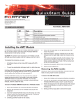
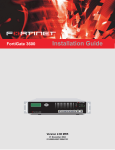
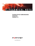
LED
HS
State
Description
Blue
Ejection latch open.
Flashing Blue
Ejection latch opened during system operation.
OOS
LED currently not in use.
PWR
Amber
The module is properly inserted in the FortiGate unit.
Off
The module is not receiving power from the FortiGate unit.
OT
HS
OOS
LED currently not in use.
LINK
ACT
PWR
Green
The correct cable is in use and the connected equipment has power.
Off
No link established.
Flashing Amber
Network activity at this interface.
Off
No network activity at this interface.
OT
1
ACT
2
LINK
ACT
3
LINK
ACT
4
LINK
ACT
5
LINK
ACT
6
LINK
ACT
7
LINK
ACT
8
LINK
ACT
LINK
ADM-FB8
FortiGate-ADM-FB8
© Copyright 2008 Fortinet Incorporated. All rights reserved.
Products mentioned in this document are trademarks or registered trademarks of their respective holders.
Regulatory Compliance
FCC Class A Part 15 CSA/CUS
10 January 2008
01-30005-0437-20080110
Checking the Package Contents
Connector
Type
Speed
Protocol
Description
Ports 1 to 8
SFP Fiber
1000 Mb
Ethernet
Fiber network connections.
QuickStart Guide
HS
OOS
HS
PWR
OT
OOS
1
ACT
PWR
2
LINK
ACT
3
LINK
ACT
4
LINK
ACT
5
LINK
ACT
6
LINK
ACT
7
LINK
ACT
8
LINK
ACT
LINK
ADM-FB8
OT
FortiGate-ADM-FB8
1
ACT
2
LINK
ACT
3
LINK
ACT
4
LINK
ACT
5
LINK
ACT
6
LINK
ACT
7
LINK
ACT
8
LINK
ACT
LINK
ADM-FB8
x4 SFP Transceivers
Copyright 2007 Fortinet Incorporated. All rights reserved.
Trademarks
Products mentioned in this document are trademarks.
QuickStart Guide
Installing the transceivers
The FortiGate ADM-FB8 module ships with four SFP transceivers that you must install for normal operation of the FortiGate ADM-FB8 module. The SFP transceivers are inserted into cage
sockets numbered 1 through 8 on the FortiGate ADM-FB8 front panel. You can install the SFP
transceivers before or after inserting the FortiGate ADM-FB8 module into a FortiGate unit.
To complete this procedure, you need:
• A FortiGate- ADM-FB8 module
• SFP transceivers
• To avoid any electrostatic discharge, install in a static free area.
If the transceiver does not easily slide in and click into place, it may not be aligned correctly
or may be upside down. If this happens, remove the SFP transceiver, realign it or rotate it
and slide it in again.
To Install the transceivers
1.
Remove the caps from SFP cage sockets on the FortiGate ADM-FB8 front panel.
2.
Hold the sides of the SFP transceiver and slide SFP transceiver into the cage socket
until it clicks into place.
FortiGate ADM-FB8 modules must be protected from static discharge and physical shock.
Only handle or work with FortiGate ADM-FB8 modules at a static-free workstation.
Handling the SFP transceivers by holding the release latch can damage the connector.
Do not force the SFP transceivers into the cage slots.
Installing the AMC module
The module should glide smoothly into the chassis. If you encounter any resistance while
sliding the module in, the module could be aligned incorrectly. Pull the module back out
and try inserting it again.
It is important to carefully seat the FortiGate ADM-FB8 module all the way into the chassis.
Only then will the FortiGate ADM-FB8 module power-on and start up correctly.
To complete this procedure, you need:
• A FortiGate ADM-FB8 module
• A FortiGate chassis with an empty AMC double-width (DW) opening.
• To avoid any electrostatic discharge, install in a static free area.
FortiGate ADM-FB8 modules are not hot swappable. The procedure for inserting the
FortiGate ADM-FB8 module into a FortiGate chassis slot requires the FortiGate unit to be
powered off.
FortiGate ADM-FB8 modules must be protected from static discharge and physical shock.
Only handle or work with FortiGate ADM-FB8 modules at a static-free workstation.
To insert a FortiGate ADM-FB8 module into a FortiGate chassis
1.
Ensure the FortiGate unit is powered off before proceeding.
2.
Attach an ESD wrist or ankle strap to your wrist or ankle and to an ESD socket or to a
bare metal surface on the chassis or frame.
3.
Remove the panel block on the FortiGate unit using the hot swap latch.
4.
Insert the FortiGate ADM-FB8 module into the empty slot in the chassis. Ensure the
Fortinet logo is right-side up. It should be on the upper-right corner of the module
5.
Carefully guide the module into the chassis.
6.
Pull out the hot swap latch on the right-hand side of the module to the extended position
if it is pushed in.
7.
Insert the module by applying moderate force to the front faceplate near the upper edge
to slide the module into the slot.
8.
Press the hot swap latch firmly to lock in the module.
9.
Power on the FortiGate unit. The hot swap (HS) LED turns on and then begins flashing.
ASM-FB8 module ports
AMC/1
AMC/3
AMC/5
AMC/7
IP:
____.____.____.____
Netmask:
____.____.____.____
IP:
____.____.____.____
Netmask:
____.____.____.____
IP:
____.____.____.____
Netmask:
____.____.____.____
IP:
____.____.____.____
Netmask:
____.____.____.____
AMC/2
AMC/4
AMC/6
AMC/8
IP:
____.____.____.____
Netmask:
____.____.____.____
IP:
____.____.____.____
Netmask:
____.____.____.____
IP:
____.____.____.____
Netmask:
____.____.____.____
IP:
____.____.____.____
Netmask:
____.____.____.____
Removing the AMC module
Should you need to remove the ADM-FB8, shut down the FortiGate unit using proper shut
down procedures.
To remove the ADM-FB8 module
1.
Ensure the FortiGate unit is powered off before proceeding.
2.
To avoid any electrostatic discharge (ESD) when handling FortiGate ASM-FB8 modules,
install in a static free area.
3.
Pull the hot swap latch on the right-hand side of the module to the extended position to
unlock the module from the FortiGate unit.
4.
Gently pull the hot swap latch to remove the module.