1
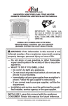
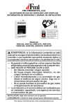
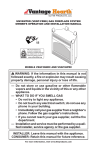
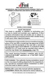
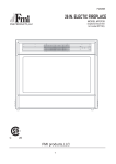
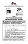
REPLACEMENT LOG SET
INSTALLATION INSTRUCTIONS
FOR BTB18, BTB24, PDG18 AND PDG24 GAS LOG HEATERS
WARNING: If log set has been in use, make sure
control knob is in the OFF position, unit is cold and
gas has been turned off.
Part No.
111835-01
111834-01
111827-01
111802-01
111817-08
111824-01
Description
Replacement Log Set 18'' - BTB18
Replacement Log Set 18'' - PDG18
Replacement Log Set 24'' - BTB24
Replacement Log Set 24'' - PDG24
Flex Tube
Compression Nut/Sleeve
3. Place new log set assembly over chassis and align holes on
bracket with holes on chassis (see Figure 2).
4. Replace six screws removed in step 1.
Qty.
1
1
1
1
1
2
Your replacement kit will contain only one log set assembly depending on your model. If there is a problem with your replacement log
set contact the authorized dealer where you bought the set or FMI
PRODUCTS, LLC at 1-866-4537.
Bracket
Items Needed for Installation:
•
•
•
5/16'' Hex Socket Wrench or Nut Driver
Phillips Screwdriver
5/8'' Wrench or Adjustable Wrench
24" Set
Chassis
1. Remove six screws from sides of log set assembly (three on
each side). Remove log set assembly (see Figure 1). Do not
pull on log assembly to remove. Work log set off chassis by
manipulating metal base.
2. 18'' models only: Disconnect flexible gas line from valve and
burner (see Figure 1). Discard flex line.
Bracket
18" Set
24" Set
Disconnect
Flexible Gas Line
Figure 1 - Removing Log Set
Chassis
18" Set
Figure 2 - Installing Replacement Log Set
Save these instructions for future reference
5. 18'' Models Only: To assemble nex flex line, insert flex tube into
end of compression nut with small opening. Place sleeve over
end of flex tube and into compression nut. Repeat for other end.
Attach new flexible gas line to valve and burner routed through
grate as shown in Figure 3. It is very important that you route
the flex line through the back leg on the grate. It could interfere
with placement in fireplace if routed around leg.
Checking Gas Connections
WARNING: Test all gas piping and connections, internal and external to unit, for leaks after installing or
servicing. Correct all leaks at once.
WARNING: Never use an open flame to check for a
leak. Apply a noncorrosive leak detection fluid to all
joints. Bubbles forming show a leak. Correct all leaks
at once.
Burner
See your owner's manual for complete instructions on checking
your gas connections.
Compression Nut
Sleeve
Compression
Nut
Sleeve
Valve
Figure 3 - Routing and Installing Flexible Gas Line for 18'' Models
(Log Set Not Shown For Clarity)
2
2701 S. Harbor Blvd.
Santa Ana, CA 92704
1-866-328-4537
www.fmiproducts.com
118843-01
REV. B
02/11