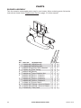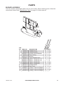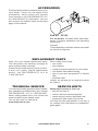
1
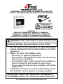
UNVENTED (VENT-FREE) INFRARED GAS HEATER SAFETY INFORMATION AND INSTALLATION MANUAL PFS ® US Models GWRP16C, GWRn18C, GWRP26C, GWRn30C, GWRP16TC, GWRn18TC, GWRP26TC, GWRn30TC VSHRP16M, VSHRP16T, VSHRN18M, VSHRN18T, VSHRP26M, VSHRP26T, VSHRN30M, and VSHRN30T WARNING: If the information in this manual is not followed exactly, a fire or explosion may result causing property damage, personal injury or loss of life. — Do not store or use gasoline or other flammable vapors and liquids in the vicinity of this or any other appliance. — WHAT TO DO IF YOU SMELL GAS • Do not try to light any appliance. • Do not touch any electrical switch; do not use any phone in your building. • Immediately call your gas supplier from a neighbor’s phone. Follow the gas supplier’s instructions. • If you cannot reach your gas supplier, call the fire department. — Installation and service must be performed by a qualified installer, service agency or the gas supplier. INSTALLER: Leave this manual with the appliance. CONSUMER: Retain this manual for future reference. For more information, visit www.fmiproducts.com TABLE OF CONTENTS Safety................................................................... 2 Local Codes......................................................... 4 Product Identification............................................ 4 Unpacking............................................................ 4 Product Features.................................................. 4 Air For Combustion and Ventilation...................... 5 Installation............................................................ 7 Operation............................................................ 14 Inspecting Heater............................................... 17 Cleaning and Maintenance................................. 17 Specifications..................................................... 18 Troubleshooting.................................................. 19 Parts................................................................... 22 Accessories........................................................ 27 Replacement Parts............................................. 27 Service Publications........................................... 27 Service Hints...................................................... 27 Technical Service............................................... 27 Warranty...............................................Back Cover Safety WARNING: Improper installation, adjustment, alteration, service or maintenance can cause injury or property damage. Refer to this manual for correct installation and operational procedures. For assistance or additional information consult a qualified installer, service agency or the gas supplier. WARNING: This is an unvented gas-fired heater. It uses air (oxygen) from the room in which it is installed. Provisions for adequate combustion and ventilation air must be provided. Refer to Air for Combustion and Ventilation section on page 5 of this manual. This appliance is only for use with the type of gas indicated on the rating plate. This appliance is not convertible for use with other gases. 2 This appliance may be installed in an aftermarket,* permanently located, manufactured (mobile) home, where not prohibited by local codes. * Aftermarket: Completion of sale, not for purpose of resale, from the manufacturer WARNING: This product contains and/or generates chemicals known to the State of California to cause cancer or birth defects or other reproductive harm. IMPORTANT: Read this owner’s manual carefully and completely before trying to assemble, operate or service this heater. Improper use of this heater can cause serious injury or death from burns, fire, explosion, electrical shock and carbon monoxide poisoning. DANGER: Carbon monoxide poisoning may lead to death! Carbon Monoxide Poisoning: Early signs of carbon monoxide poisoning resemble the flu, with headaches, dizziness or nausea. If you have these signs, the heater may not be working properly. Get fresh air at once! Have heater serviced. Some people are more affected by carbon monoxide than others. These include pregnant women, people with heart or lung disease or anemia, those under the influence of alcohol and those at high altitudes. www.fmiproducts.com 125311-01A SAFETY Continued Natural and Propane/LP Gas: Natural and propane/LP gases are odorless. An odormaking agent is added to these gases. The odor helps you detect a gas leak. However, the odor added to the gas can fade. Gas may be present even though no odor exists. Make certain you read and understand all warnings. Keep this manual for reference. It is your guide to safe and proper operation of this heater. WARNING: Any change to this heater or its controls can be dangerous. WARNING: Do not use a blower insert, heat exchanger insert or other accessory not approved for use with this heater. Due to high temperatures, the appliance should be located out of traffic and away from furniture and draperies. Do not place clothing or other flammable material on or near the appliance. Never place any objects on the heater. Surface of heater becomes very hot when running heater. Keep children and adults away from hot surface to avoid burns or clothing ignition. Heater will remain hot for a time after shutdown. Allow surface to cool before touching. Carefully supervise young children when they are in the room with heater. Make sure grill guard is in place before running heater. 125311-01A Keep the appliance area clear and free from combustible materials, gasoline and other flammable vapors and liquids. 1. This appliance is only for use with the type of gas indicated on the rating plate. This appliance is not convertible for use with other gases. 2. Do not place propane/LP supply tank(s) inside any structure. Locate propane/LP supply tank(s) outdoors. 3. This heater shall not be installed in a bedroom or bathroom. 4. If you smell gas •shut off gas supply •do not try to light any appliance •do not touch any electrical switch; do not use any phone in your building •immediately call your gas supplier from a neighbor’s phone. Follow the gas supplier’s instructions •if you cannot reach your gas supplier, call the fire department 5. Manual Control Models Always run heater with plaque control knob at the 1, 2, 3 or 4 locked positions. Never set control knob between locked positions. Poor combustion and higher levels of carbon monoxide may result. 6. This heater needs fresh, outside air ventilation to run properly. This heater has an Oxygen Depletion Sensing (ODS) safety shutoff system. The ODS shuts down the heater if not enough fresh air is available. See Air for Combustion and Ventilation, page 5. 7. Keep all air openings in front and bottom of heater clear and free of debris. This will insure enough air for proper combustion. 8. If heater shuts off, do not relight until you provide fresh, outside air. If heater keeps shutting off, have it serviced. 9. Do not run heater • where flammable liquids or vapors are used or stored • under dusty conditions 10.Do not use heater if any part has been under water. Immediately call a qualified service technician to inspect the room heater and to replace any part of the control system and any gas control which has been under water. www.fmiproducts.com 3 SAFETY Continued 11. Turn off and unplug heater and let cool before servicing. Only a qualified service person should service and repair heater. 12. Operating heater above elevations of 4,500 feet (1,371 m) could cause pilot outage. 13. To prevent performance problems, do not use propane/LP fuel tank of less than 100 lbs. (45 kg) capacity. 14.Before using furniture polish, wax, carpet cleaner or similar products, turn heater off. If heated, the vapors from these products may create a white powder residue within burner box or on adjacent walls or furniture. 15.Provide adequate clearances around air openings. Local Codes Install and use heater with care. Follow all local codes. In the absence of local codes, use the latest edition of The National Fuel Gas Code ANSI Z223/NFPA 54*. *Available from: American National Standards Institute, Inc. 1430 Broadway New York, NY 10018 National Fire Protection Association, Inc. Batterymarch Park Quincy, MA 02269 Product Identification Ignitor Button Unpacking Control Knob Grill Guard Plaque Heater Cabinet State of Massachusetts: The installation must be made by a licensed plumber or gas fitter in the Commonwealth of Massachusetts. Sellers of unvented propane or natural gas-fired supplemental room heaters shall provide to each purchaser a copy of 527 CMR 30 upon sale of the unit. Vent-free gas products are prohibited for bedroom and bathroom installation in the Commonwealth of Massachusetts. Front Panel Figure 1 - Vent-Free Gas Heater (actual heater may vary from illustration 1. Remove heater from carton. 2. Remove all protective packaging applied to heater for shipment. 3. Check heater for any shipping damage. If heater is damaged call FMI PRODUCTS, LLC at 1-866-328-4537 for replacement parts before returning to dealer. Product Features Safety Device This heater has a pilot with an Oxygen Depletion Sensing (ODS) safety shutoff system. The ODS/pilot is a required feature for vent-free room heaters. The ODS/pilot shuts off the heater if there is not enough fresh air. Ignition System Some models are equipped with a piezo ignitor that requires no matches, batteries or other sources to light heater. Other heaters are equipped with an electronic ignitor to light heater fuel supply. Thermostatic Heat Control (Thermostat Models Only) Thermostat models have a thermostat sensing bulb and a control valve. This results in the greatest heater comfort. This can also result in lower gas bills. 4 www.fmiproducts.com 125311-01A Air For Combustion and Ventilation WARNING: This heater shall not be installed in a room or space unless the required volume of indoor combustion air is provided by the method described in the National Fuel Gas Code, ANSI Z223.1/NFPA 54, the International Fuel Gas Code, or applicable local codes. Read the following instructions to insure proper fresh air for this and other fuel-burning appliances in your home. Today’s homes are built more energy efficient than ever. New materials, increased insulation and new construction methods help reduce heat loss in homes. Home owners weather strip and caulk around windows and doors to keep the cold air out and the warm air in. During heating months, home owners want their homes as airtight as possible. While it is good to make your home energy efficient, your home needs to breathe. Fresh air must enter your home. All fuel-burning appliances need fresh air for proper combustion and ventilation. Exhaust fans, heaters, clothes dryers and fuel burning appliances draw air from the house to operate. You must provide adequate fresh air for these appliances. This will insure proper venting of vented fuel-burning appliances. PROVIDING ADEQUATE VENTILATION The following are excerpts from National Fuel Gas Code. ANSI Z223.1/NFPA 54, Air for Combustion and Ventilation. All spaces in homes fall into one of the three following ventilation classifications: 1. Unusually Tight Construction 2. Unconfined Space 3. Confined Space The information on pages 5 through 7 will help you classify your space and provide adequate ventilation. 125311-01A Unusually Tight Construction The air that leaks around doors and windows may provide enough fresh air for combustion and ventilation. However, in buildings of unusually tight construction, you must provide additional fresh air. Unusually tight construction is defined as construction where: a. walls and ceilings exposed to the outside atmosphere have a continuous water vapor retarder with a rating of one perm (6x10-11 kg per pa-sec-m2) or less with openings gasketed or sealed and b. weather stripping has been added on openable windows and doors and c. caulking or sealants are applied to areas such as joints around window and door frames, between sole plates and floors, between wall-ceiling joints, between wall panels, at penetrations for plumbing, electrical and gas lines and at other openings. If your home meets all of the three criteria above, you must provide additional fresh air. See Ventilation Air From Outdoors, page 7. If your home does not meet all of the three criteria above, proceed to Determining Fresh-Air Flow For Heater Location. Confined Space and Unconfined Space The National Fuel Gas Code ANSI Z223.1/ NFPA 54 defines a confined space as a space whose volume is less than 50 cubic feet per 1,000 Btu per hour (4.8 m3 per kw) of the aggregate input rating of all appliances installed in that space and an unconfined space as a space whose volume is not less than 50 cubic feet per 1,000 Btu per hour (4.8 m3 per kw) of the aggregate input rating of all appliances installed in that space. Rooms communicating directly with the space in which the appliances are installed*, through openings not furnished with doors, are considered a part of the unconfined space. * Adjoining rooms are communicating only if there are doorless passageways or ventilation grills between them. www.fmiproducts.com 5 AIR FOR COMBUSTION AND VENTILATION Continued DETERMINING FRESH-AIR FLOW FOR Heater LOCATION Determining if You Have a Confined or Unconfined Space Use this work sheet to determine if you have a confined or unconfined space. Space: Includes the room in which you will install heater plus any adjoining rooms with doorless passageways or ventilation grills between the rooms. 1. Determine the volume of the space (length x width x height). Length x Width x Height =__________cu. ft. (volume of space) Example: Space size 20 ft. (6.1m) (length) x 16 ft. (4.88m) (width) x 8 ft. (2.44 m) (ceiling height) = 2,560 cu. ft. (72.49 m2)(volume of space) If additional ventilation to adjoining room is supplied with grills or openings, add the volume of these rooms to the total volume of the space. 2. Multiply the space volume by 20 to determine the maximum Btu/Hr the space can support. _ ________ (volume of space) x 20 = (Maximum Btu/Hr the space can support) Example: 2,560 cu. ft. (72.49 m2) (volume of space) x 20 = 51,200 (maximum Btu/Hr the space can support) 3. Add the Btu/Hr of all fuel burning appliances in the space. Vent-free heater __________ Btu/Hr Gas water heater* __________ Btu/Hr Gas furnace __________ Btu/Hr Vented gas heater __________ Btu/Hr Gas heater logs __________ Btu/Hr Other gas appliances*+_ _________ Btu/Hr Total =__________ Btu/Hr * Do not include direct-vent gas appliances. Direct-vent draws combustion air from the outdoors and vents to the outdoors. Example: 40,000 Btu/Hr Gas water heater __________ 20,000 Btu/Hr Vent-free heater +__________ 60,000 Btu/Hr Total =__________ 4. Compare the maximum Btu/Hr the space can support with the actual amount of Btu/ Hr used. _ _______ Btu/Hr (maximum can support) _ _______ Btu/Hr (actual amount used) Example: 51,200 Btu/Hr (maximum the space can support) 60,000 Btu/Hr (actual amount of Btu/Hr used) 6 The space in the example is a confined space because the actual Btu/Hr used is more than the maximum Btu/Hr the space can support. You must provide additional fresh air. Your options are as follows: A. Rework worksheet, adding the space of an adjoining room. If the extra space provides an unconfined space, remove door to adjoining room or add ventilation grills between rooms. See Ventilation Air From Inside Building. B. Vent room directly to the outdoors. See Ventilation Air From Outdoors, page 7. C. Install a lower Btu/Hr heater, if lower Btu/Hr size makes room unconfined. If the actual Btu/Hr used is less than the maximum Btu/Hr the space can support, the space is an unconfined space. You will need no additional fresh air ventilation. WARNING: If the area in which the heater may be operated does not meet the required volume for indoor combustion air, combustion and ventilation air shall be provided by one of the methods described in the National Fuel Gas Code, ANSI Z223.1/NFPA 54, the International Fuel Gas Code, or applicable local codes. VENTILATION AIR Ventilation Air From Inside Building This fresh air would come from an adjoining unconfined space. When ventilating to an adjoining unconfined space, you must provide two permanent openings: one within 12" (30.5 cm) of the ceiling and one within 12" (30.5 cm) of the floor on the wall connecting the two spaces (see options 1 and 2, Figure 2, page 7). You can also remove door into adjoining room (see option 3, Figure 2, page 7). Follow the National Fuel Gas Code, ANSI Z223.1/ NFPA 54, Air for Combustion and Ventilation for required size of ventilation grills or ducts. www.fmiproducts.com 125311-01A AIR FOR COMBUSTION AND VENTILATION Continued 12" Ventilation Grills into Adjoining Room, Option 1 Ventilation Grills Into Adjoining Room, Option 2 Or Remove Door into Adjoining Room, Option 3 ing and one within 12" (30.5 cm) of the floor. Connect these items directly to the outdoors or spaces open to the outdoors. These spaces include attics and crawl spaces. Follow the National Fuel Gas Code, ANSI Z223.1/NFPA 54, Air for Combustion and Ventilation for required size of ventilation grills or ducts. IMPORTANT: Do not provide openings for inlet or outlet air into attic if attic has a thermostatcontrolled power vent. Heated air entering the attic will activate the power vent. 12" Outlet Air Ventilated Attic Outlet Air To Attic Figure 2 - Ventilation Air from Inside Building Ventilation Air From Outdoors Provide extra fresh air by using ventilation grills or ducts. You must provide two permanent openings: one within 12" (30.5 cm) of the ceil- To Crawl Space Inlet Air Inlet Air Ventilated Crawl Space Figure 3 - Ventilation Air from Outdoors Installation NOTICE: This heater is intended for use as supplemental heat. Use this heater along with your primary heating system. Do not install this heater as your primary heat source. If you have a central heating system, you may run system’s circulating blower while using heater. This will help circulate the heat throughout the house. In the event of a power outage, you can use this heater as your primary heat source. WARNING: A qualified service person must install heater. Follow all local codes. WARNING: This appliance is equipped for either natural gas or propane/LP gas but not both. Gas type is indicated on the rating plate. Field conversion is not permitted. 125311-01A CHECK GAS TYPE Use only the correct gas type (natural or propane/LP) for your unit. If your gas supply is not correct, do not install heater. Call dealer where you bought heater for proper type heater. INSTALLATION ITEMS Before installing heater, make sure you have the items listed below. • for propane/LP gas, external regulator (supplied by installer) • piping (check local codes) • sealant (resistant to propane/LP gas) • equipment shutoff valve * • ground joint union • sediment trap • tee joint • pipe wrench • for natural gas, test gauge connection* • hardware packet (included) - wall anchor (4) 095112-02 - red key (1) 095116-01 - pan head screw, black (4) 097403-02 - nylon spacer (2) 099064-02 - clip (1) 099123-01 - Phillips head screw, silver (4) 100159-02 * An equipment shutoff valve with 1/8" NPT tap is an acceptable alternative to test gauge connection. The optional equipment shutoff valve can be purchased from your dealer. www.fmiproducts.com 7 INSTALLATION Continued LOCATING HEATER This heater is designed to be mounted on a wall. WARNING: Maintain the minimum clearances shown in Figure 4. If you can, provide greater clearances from floor, ceiling and joining wall. You can locate heater on floor, away from a wall. An optional floor mounting stand is needed. Purchase the floor mounting stand from your dealer. See Accessories, page 27, if stand is not included with your heater. WARNING: Never install the heater • in a bedroom or bathroom • in a recreational vehicle • where curtains, furniture, clothing or other flammable objects are less than 36" (91.5 cm) from the front, top or sides of the heater • as a fireplace insert • in high traffic areas • in windy or drafty areas CAUTION: If you install the heater in a home garage • heater pilot and burner must be at least 18" (45.7 cm) above floor • locate heater where moving vehicle will not hit it CAUTION: This heater creates warm air currents. These currents move heat to wall surfaces next to heater. Installing heater next to vinyl or cloth wall coverings or operating heater where impurities (such as, but not limited to, tobacco smoke, aromatic candles, cleaning fluids, oil or kerosene lamps, etc.) in the air exist, may discolor walls or cause odors. 8 IMPORTANT: Vent-free heaters add moisture to the air. Although this is beneficial, installing heater in rooms without enough ventilation air may cause mildew to form from too much moisture. See Air for Combustion and Ventilation, page 5. If high humidity is experienced, a dehumidifier may be used to help lower the water vapor content in the air. For convenience and efficiency, install heater • where there is easy access for operation, inspection and service • in coldest part of room If not included with your heater, an optional fan kit is available from your dealer. See Accessories, page 27. If planning to use fan, locate heater near an electrical outlet (see page 16). CEILING 10" (25.4 cm) Minimum From Sides Of Heater 36" (91.5 cm) Minimum Right Side Left Side 36" (91.5 cm) Minimum To Top Surface Of Carpeting, 2" (5.1 cm) Tile Or Other Combustible Material FLOOR Figure 4 - Mounting Clearances As Viewed From Front of Heater THERMOSTAT SENSING BULB (Thermostat Models Only) The thermostat sensing bulb has been placed below the heater. 1. Place clip on thermostat sensing bulb as shown in Figure 5. Clip is provided in hardware package. 2. Snap clip into upper mounting hole as shown in Figure 5. Mounting hole is located on lower left edge on back of heater. Make sure thermostat sensing bulb is pointing up. Thermostat Sensing Bulb Clip Figure 5 - Attaching Thermostat Sensing Bulb www.fmiproducts.com 125311-01A INSTALLATION Continued INSTALLING HEATER TO WALL Mounting Bracket Locate mounting bracket in heater carton. Remove mounting bracket from heater carton. Figure 6 - Mounting Bracket Removing Front Panel Of Heater 1. Remove the four painted screws, two on each side of front panel. 2. Pull bottom of front panel forward, then out. 3. Remove any remaining packaging materials. 1. Tape mounting bracket to wall where heater will be located. Make sure mounting bracket is level. WARNING: Maintain minimum clearances shown in Figure 8. If you can, provide greater clearances from floor and joining wall. 2. Mark screw locations on wall (see Figure 8). Note: Only mark last hole on each end of mounting bracket. Insert mounting screws through these holes only. 3. Remove tape and mounting bracket from wall. 12" Min. Screw Adjoining Wall Front Panel Marking Screw Locations 14" Only Insert Mounting Screws Through Last Hole On Each End 19 3/4" Min. Floor 3 Plaque Heater Figure 7 - Removing Front Panel of Heater (actual heater may vary from Illustration) Methods For Attaching Mounting Bracket To Wall Only use last hole on each end of mounting bracket to attach bracket to wall. These two holes are 14" (35.6 cm) apart from their centers. Attach mounting bracket to wall in one of two ways: 1. Attaching to wall stud 2. Attaching to wall anchor Attaching to Wall Stud: This method provides the strongest hold. Insert mounting screws through mounting bracket and into wall studs. Attaching to Wall Anchor: This method allows you to attach mounting bracket to hollow walls (wall areas between studs) or to solid walls (concrete or masonry). Decide which method better suits your needs. Either method will provide a secure hold for the mounting bracket. 125311-01A Adjoining Wall 16" Min. 14" Only Insert Mounting Screws Through Last Hole On Each End 19 3/4" Min. Floor 5 Plaque Heaters Figure 8 - Mounting bracket Clearances Attaching Mounting Bracket To Wall Note: Wall anchors, mounting screws and spacers are in hardware package. The hardware package is provided with heater. Attaching To Wall Stud Method For attaching mounting bracket to wall studs 1. Drill holes at marked locations using 9/64" drill bit. 2. Place mounting bracket onto wall. Line up last hole on each end of bracket with holes drilled in wall. 3. Insert mounting screws through bracket and into wall studs. 4. Tighten screws until mounting bracket is firmly fastened to wall studs. www.fmiproducts.com 9 INSTALLATION Continued Attaching To Wall Anchor Method For attaching mounting bracket to hollow walls (wall areas between studs) or solid walls (concrete or masonry) 1. Drill holes at marked locations using 5/16" drill bit. For solid walls (concrete or masonry), drill at least 1" (2.5 cm) deep. 2. Fold wall anchor as shown in Figure 9. 3. Insert wall anchor (wings first) into hole. Tap anchor flush to wall. 4. For thin walls [1/2" (1.3 cm) or less], insert red key into wall anchor. Push red key to “pop” open anchor wings. IMPORTANT: Do not hammer key! For thick walls [over 1/2" (1.3 cm) thick] or solid walls, do not pop open wings. 5. Place mounting bracket onto wall. Line up last hole on each end of bracket with wall anchors. 6. Insert mounting screws through bracket and into wall anchors. 7. Tighten screws until mounting bracket is firmly fastened to wall. 3. Remove heater from mounting bracket. 4. If installing bottom mounting screws into hollow or solid wall, install wall anchors. Follow steps 1 through 4 under Attaching To Wall Anchor Method. If installing bottom mounting screw into wall stud, drill holes at marked locations using 9/64" drill bit. 5. Replace heater onto mounting bracket. 6. Place spacers between bottom mounting holes and wall anchor or drilled hole. 7. Hold spacer in place with one hand. With other hand, insert mounting screw through bottom mounting hole and spacer. Place tip of screw in opening of wall anchor or drilled hole. 8. Tighten both screws until heater is firmly secured to wall. Do not over tighten. Note: Do not replace front panel at this time. Replace front panel after making gas connections and checking for leaks (see page 11). Front View Figure 9 - Folding Figure 10 - Popping Anchor Open Anchor Wings for Thin Walls Placing Heater On Mounting Bracket 1. Locate two horizontal slots on back panel of heater. 2. Place heater onto mounting bracket. Slide horizontal slots onto stand-out tabs on mounting bracket. Horizontal Slots Stand-Out Tab Mounting Bracket (attached to wall) Figure 11 - Mounting Heater onto Mounting Bracket Installing Bottom Mounting Screws 1. Locate two bottom mounting holes. These holes are near bottom on back panel of heater (see Figure 12). 2. Mark screw locations on wall. 10 Wall Heater Spacer Side View Figure 12 - Installing Bottom Mounting Screws Mounting heater to floor With optional floor kit Mounting Base Feet to Heater Note: A 90° elbow is required for mounting this unit and must be installed BEFORE base feet to provide proper clearance (see Figure 15, page 12). 1. Lay heater cabinet on its back on a table with the heater bottom overhanging table edge. 2. Apply pipe joint sealant lightly to male NPT threads of elbow. Hold pressure regulator with a wrench when connecting elbow. Do not overtighten elbow to regulator. Regulator body could be damaged. www.fmiproducts.com 125311-01A INSTALLATION Continued 3. Align holes in base foot with mounting holes on bottom of cabinet (see Figure 13). 4. Secure base foot to heater using sheet metal screws. 5. Repeat for other side. Wood Screw Base Foot Sheet Metal Screw Figure 13 - Installing Base Feet (actual heater may vary from illustration) Mounting Base Feet to Floor 1. Remove front panel (see Removing Front Panel of Heater, page 9). 2. Position heater with base feet in desired location. Mark holes for drilling. Remove heater with base. 3. For carpeted floors, make a small cut with a sharp knife at marked locations prior to drilling. If mounting base to a wood floor, drill 1/8" diameter hole, 3/4" deep. (Do not use anchors in wood floors). If mounting base to a concrete floor, drill with 1/4" diameter concrete drill bit, 13/8" into floor. Insert anchors completely into holes. 4. Reposition heater with base feet over holes. Secure base to floor with wood screws. See Figure 13. CONNECTING TO GAS SUPPLY WARNING: This appliance requires a 3/8" NPT (National Pipe Thread) inlet connection to the pressure regulator. WARNING: A qualified service person must connect heater to gas supply. Follow all local codes. WARNING:Fornaturalgas,never connect heater to private (non-utility) gas wells. This gas is commonly known as wellhead gas. 125311-01A IMPORTANT: For natural gas, check gas line pressure before connecting heater to gas line. Gas line pressure must be no greater than 10.5" W.C.. If gas line pressure is higher, heater regulator damage could occur. CAUTION: For propane/LP gas, never connect heater directly to the propane/LP supply. This heater requires an external regulator (not supplied). Install the external regulator between the heater and propane/LP supply. For propane/LP gas, the installer must supply an external regulator. The external regulator will reduce incoming gas pressure. You must reduce incoming gas pressure to between 11" and 14" W.C.. If you do not reduce incoming gas pressure, heater regulator damage could occur. Install the external regulator with the vent pointing down as shown in Figure 14. Pointing the vent down protects it from freezing rain or sleet. CAUTION: Use only new, black iron or steel pipe. Internally-tinned copper tubing may be used in certain areas. Check your local codes. Use pipe of large enough diameter to allow proper gas volume to heater. If pipe is too small, undue loss of volume will occur. Typical Inlet Pipe Diameters 16-18,000 Btu/hr models - 3/8" or greater 26-30,000 Btu/hr models - 1/2" or greater Installation must include equipment shutoff valve, union and plugged 1/8" NPT tap. Locate NPT tap within reach for test gauge hook up. NPT tap must be upstream from heater (see Figure 15, page 12). Propane/LP Supply Tank External Regulator with Vent Pointing Down Figure 14 - Equipment Regulator with Vent Pointing Down www.fmiproducts.com 11 INSTALLATION Continued IMPORTANT: Install an equipment shutoff valve in an accessible location. The equipment shutoff valve is for turning on or shutting off the gas to the appliance. Check your building codes for an special requirements for locating equipment shutoff valve to heater. Apply pipe joint sealant lightly to male NPT threads. This will prevent excess sealant from going into pipe. Excess sealant in pipe could result in clogged heater valves. Pressure Regulator Test Gauge Connection* Regulator Bracket Heater Cabinet Tee Joint Reducer Bushing to 1/8" NPT 1/8" NPT Plug Tap 3/8" NPT Pipe Nipple Ground Joint Union Equipment Shutoff Valve* Natural Gas 3" From Gas Min. Meter (7" W.C. to 10.5" W.C. Pressure) Tee Pipe Cap Propane/LP Joint Nipple From External Sediment Trap Regulator (11" W.C. to 14" W.C. Pressure) Refer to connector's instructions Flexline See illustration 3/8" NPT/ 1/2" above for Flare 90° Elbow detail Connection Using Flexline Figure 15 - Gas Connection * An equipment shutoff valve with 1/8" NPT tap is an acceptable alternative to test gauge connection. Purchase the optional equipment shutoff valve from your dealer. 12 WARNING: Use pipe joint sealant that is resistant to liquid petroleum (LP) gas. Install sediment trap in supply line as shown in Figure 15. Locate sediment trap where it is within reach for cleaning. Locate sediment trap where trapped matter is not likely to freeze. A sediment trap traps moisture and contaminants. This keeps them from going into heater controls. If sediment trap is not installed or is installed wrong, heater may not run properly. IMPORTANT: Hold the pressure regulator with wrench when connecting it to gas piping and/or fittings. Do not over tighten pipe connection to regulator. The regulator body could be damaged. CHECKING GAS CONNECTIONS WARNING: Test all gas piping and connections, internal and external to unit, for leaks after installing or servicing. Correct all leaks at once. WARNING: Never use an open flame to check for a leak. Apply a noncorrosive leak detection fluid to all joints. Bubbles forming show a leak. Correct all leaks at once. CAUTION: For propane/LP units, make sure external regulator has been installed between propane/LP supply and heater. See guidelines under Connecting to Gas Supply, page 11. Pressure Testing Gas Supply Piping System Test Pressures In Excess Of 1/2 PSIG (3.5 kPa) 1. Disconnect appliance with its appliance main gas valve (control valve) and equipment shutoff valve from gas supply piping. Pressures in excess of 1/2 psig will damage heater regulator. www.fmiproducts.com 125311-01A INSTALLATION Continued 2. Cap off open end of gas pipe where equipment shutoff valve was connected. 3. Pressurize supply piping system by either opening propane/LP supply tank valve for propane/LP gas or opening main gas valve located on or near gas meter for natural gas or using compressed air. 4. Check all joints of gas supply piping system. Apply a commercial leak detection solution to all joints. Bubbles forming show a leak. 5. Correct all leaks at once. 6. Reconnect heater and equipment shutoff valve to gas supply. Check reconnected fittings for leaks. Test Pressures Equal To or Less Than 1/2 PSIG (3.5 kPa) 1. Close equipment shutoff valve (see Figure 16). 2. Pressurize supply piping system by either opening propane/LP supply tank valve for propane/LP gas or opening main gas valve located on or near gas meter for natural gas or using compressed air. 3. Check all joints from gas meter for natural gas (see Figure 17)) or propane/LP supply to equipment shutoff valve (see Figure 18). Apply a noncorrosive leak detection fluid to all joints. Bubbles forming show a leak. 4. Correct all leaks at once. Pressure Testing Heater Gas Connections 1. Open equipment shutoff valve (see Figure 16). Equipment Shutoff Valve Open 2. For natural gas, open main gas valve located on or near gas meter. For propane/ LP gas, open propane/LP supply tank valve. 3. Make sure control knob of heater is in the OFF position. 4. Check all joints from equipment shutoff valve to thermostat gas valve (see Figure 17 or 18). Apply a noncorrosive leak detection fluid to all joints. Bubbles forming show a leak. 5. Correct all leaks at once. 6. Light heater (see Operation page 14). Check all other internal joints for leaks. 7. Turn off heater (see To Turn Off Gas to Appliance, page 15). 8. Replace front panel. Thermostat Gas Valve Gas Meter Equipment Shutoff Valve Figure 17 - Checking Gas Joints for Natural Gas (actual heater may vary from illustration) Thermostat Gas Valve Propane/LP Supply Tank Closed Figure 16 - Equipment Shutoff Valve Equipment Shutoff Valve Figure 18 - Checking Gas Joints for Propane/LP Gas (actual heater may vary from illustration) 125311-01A www.fmiproducts.com 13 Operation FOR YOUR SAFETY READ BEFORE LIGHTING WARNING: If you do not follow these instructions exactly, a fire or explosion may result causing property damage, personal injury or loss of life. A. This appliance has a pilot which must be lighted by hand. When lighting the pilot, follow these instructions exactly. B. BEFORE LIGHTING smell all around the appliance area for gas. Be sure to smell next to the floor because some gas is heavier than air and will settle on the floor. WHAT TO DO IF YOU SMELL GAS •Do not try to light any appliance. •Do not touch any electric switch; do not use any phone in your building. •Immediately call your gas supplier from a neighbor’s phone. Follow the gas supplier’s instructions. •If you cannot reach your gas supplier, call the fire department. C. Use only your hand to push in or turn the gas control knob. Never use tools. If the knob will not push in or turn by hand, don’t try to repair it, call a qualified service technician or gas supplier. Force or attempted repair may result in a fire or explosion. D. Do not use this appliance if any part has been under water. Immediately call a qualified service technician to inspect the appliance and to replace any part of the control system and any gas control which has been under water. 7. 8. 9. Control Knob Figure 19 - Control Knob in the OFF Position for Manual Control Models Control Knob OT 1. STOP! Read the safety information above. 2. Make sure equipment shutoff valve is fully open. 3. Turn off any electric power to the appliance if service is to be performed. 4. Turn control knob clockwise to the OFF position. 5. Wait five (5) minutes to clear out any gas. Then smell for gas, including near the floor. If you smell gas, STOP! Follow “B” 14 O LIGHTING INSTRUCTIONS 6. in the safety information, column 1. If you don’t smell gas, go to the next step. Thermostat Models: Turn control knob counterclockwise to the PILOT position. Press in control knob for five (5) seconds. Manual Models: Press in and turn control knob counterclockwise to the PILOT position. Keep control knob pressed in for five (5) seconds. With control knob pressed in, push down and release ignitor button. This will light pilot. The pilot is attached to the front of burner. Note: You may be running this heater for the first time after hooking up to gas supply. If so, you may need to press in control knob for 30 seconds or more. This will allow air to bleed from the gas system. If needed, keep pressing ignitor button until pilot lights. If ignitor does not light pilot, refer to Troubleshooting, page 18 or contact a qualified service person or gas supplier for repairs. Until repairs are made, light pilot with match. To light pilot with match, see Manual Lighting Procedure, page 16. Keep control knob pressed in for 30 seconds after lighting pilot. After 30 seconds, release control knob. • If control knob does not pop out when released, contact a qualified service person or gas supplier for repairs. Note: If pilot goes out, repeat steps 4 through 7. Wait one (1) minute before lighting pilot Turn control knob counterclockwise to desired heating level. The main burner should light. Manual control heaters should be used in locked positions. Figure 20 - Control Knob in the OFF Position for Thermostat Models www.fmiproducts.com 125311-01A OPERATion Continued 10.To shut off burners only and leave pilot lit, turn control knob clockwise to the PILOT position. Control Knob WARNING: Always operate manual control heaters at the locked positions. Operation between these positions may create a possible health hazard if used in a poorly ventilated room. Read owner’s manual for complete instructions. CAUTION: Do not try to adjust heating levels by using the equipment shutoff valve. Thermocouple Ignitor Electrode Pilot Burner To Select heating level WARNING: When running heater, set control knob at LOW, MED or HI locked positions. Never set control knob between locked positions. Poor combustion and higher levels of carbon monoxide may result. Slightly press in control knob and turn counterclockwise to the LOW, MED or HI positions (see Figure 22). IMPORTANT: Release downward pressure while turning control knob. Control knob will lock at the desired position. 125311-01A HI HI MED MED LOW LOW thermostat Models Turn thermostat control knob counterclockwise to the desired heating level. The main burner should light. Set control knob to any heat level between 1 and 5 (see Figure 23). CAUTION: Do not try to adjust heating levels by using the equipment shutoff valve. Manual Control Models 26,000 & 30,000 Btu/Hr OFF OFF Figure 22 - Burner Patterns for Manual Control Models Control Knob Figure 21 - Pilot 16,000 & 18,000 Btu/Hr 16,000 & 18,000 Btu/Hr 26,000 & 30,000 Btu/Hr ON ON OFF OFF Figure 23 - Burner Patterns TO TURN OFF GAS TO APPLIANCE 1. Turn control knob clockwise to the OFF position. 2. Turn off all electric power to the appliance if service is to be performed. 3. Close equipment shutoff valve (see Figure 16, page 13). www.fmiproducts.com 15 OPERATion Continued Thermostat Control Operation CAUTION: Label all wires prior to disconnection when servicing controls. Wiring errors can cause improper and dangerous operation. The thermostatic control used on these models differs from standard thermostats. Standard thermostats simply turn on and off the burner. The thermostat used on this heater senses the room temperature. At times the room may exceed the set temperature. If so, the burner will shut off. The burner will cycle back on when room temperature drops below the set temperature. The control knob can be set to any comfort level between 1 and 5. All plaques will turn off and on. Note: The thermostat sensing bulb measures the temperature of air near the heater cabinet. This may not always agree with room temperature (depending on housing construction, installation location, room size, open air temperatures, etc.) Frequent use of your heater will let you determine your own comfort levels. Extension Cord Use extension cord if needed. The cord must have a three-prong, grounding plug and a three-hole receptacle. Make sure cord is in good shape. It must be heavy enough to carry the current needed. An undersized cord will cause a drop in line voltage. This will result in loss of power and overheating. Use a No. 16 AWG cord for lengths less than 50 feet. MANUAL LIGHTING PROCEDURE CAUTION: Verify proper operation after servicing. 1. Remove front panel (see Figure 7, page 9). 2. Follow steps 1 through 5 under Lighting Instructions, page 14. 3. With control knob pressed in, strike match. Hold match to pilot until pilot lights. 4. Keep control knob pressed in for 30 seconds after lighting pilot. After 30 seconds, release control knob. Now follow step 9 under Lighting Instructions, page 14. 5. Replace front panel. CAUTION: Do not plug power cord into electrical outlet until installation is complete. Operating Blower The blower is connected to a thermostat. When unit heats up, the blower will operate. A few minutes after unit cycles off or is turned off, blower will shut off. Blower will cycle on and off in this manner. Note: If you have a heater with a thermostat, the heater and blower will not turn off and on at exactly the same time. Blower cycle times will vary with heat setting selected. Blower Operation Grounded Outlet WARNING: Blower accessory must be grounded. Blower comes with a three-prong, grounding plug as shown in Figure 24. The plug is your protection against electrical shock. Plug it into a standard, three-hole, grounded, outlet. If cord needs replacing, use only a cord with a three-prong, grounding plug. 16 Figure 24 - Grounding Plug Thermostat Sensor Switch 110/115 V.A.C. Black Green White Blower Motor Black White Green Figure 25 - Wiring Diagram for Blower Accessory www.fmiproducts.com 125311-01A Inspecting heaters Check pilot flame pattern and burner flame patterns often. PILOT FLAME PATTERN Figure 26 shows a correct pilot flame pattern. Figure 27 shows an incorrect pilot flame pattern. The incorrect pilot flame is not touching the thermocouple. This will cause the thermocouple to cool. When the thermocouple cools, the heater will shut down. If pilot flame pattern is incorrect, as shown in Figure 27 • turn heater off (see To Turn Off Gas to Appliance, page 15) • see Troubleshooting, page 18 Note: The pilot flame on natural gas units will have a slight curve, but flame should be blue and have no yellow or orange color. Blue Flame Thermocouple Pilot Burner BURNER flame pattern Figure 28 shows a correct burner flame pattern. Figure 29 shows an incorrect burner flame pattern. If burner flame pattern is incorrect, as shown in Figure 29 • turn heater off (see To Turn Off Gas to Appliance, page 15) • see Troubleshooting, page 18 Figure 28 - Correct Burner Flame Pattern Figure 26 - Correct Pilot Flame Pattern Yellow Flame Thermocouple Pilot Burner Figure 29 - Incorrect Burner Flame Pattern Figure 27 - Incorrect Pilot Flame Pattern Cleaning and Maintenance WARNING: Turn off heater and let cool before cleaning. CAUTION: You must keep control areas, burner and circulating air passageways of heater clean. Inspect these areas of heater before each use. Have heater inspected yearly by a qualified service person. Heater may need more frequent cleaning due to excessive lint from carpeting, bedding material, pet hair, etc. 125311-01A WARNING: Failure to keep the primary air opening(s) of the burner(s) clean may result in sooting and property damage. ODS/PILOT AND BURNER Use a vacuum cleaner, pressurized air or small, soft bristled brush to clean. Burner Pilot Air Inlet The primary air inlet holes allow the proper amount of air to mix with the gas. This provides a clean burning flame. Keep these holes clear of dust, dirt and lint. Clean these air inlet holes prior to each heating season. Blocked air holes will create soot. We recommend that you clean the unit every three months during operation and have heater inspected yearly by a qualified service person. www.fmiproducts.com 17 CLEANING AND MAINTENANCE Continued We also recommend that you keep the burner tube and pilot assembly clean and free of dust and dirt. To clean these parts we recommend using compressed air no greater than 30 PSI. Your local computer store, hardware store or home center may carry compressed air in a can. If using compressed air in a can, please follow the directions on the can. If you don’t follow directions on the can, you could damage the pilot assembly. 1. Shut off unit, including pilot. Allow unit to cool for at least thirty minutes. 2. Inspect burner, pilot and primary air inlet holes on orifice holder for dust and dirt (see Figure 30). 3. Blow air through the ports/slots and holes in the burner. 4. Never inset objects into the pilot tube. 5. Blow air into the primary air holes on the orifice holder. Clean pilot assembly also. A yellow tip on the pilot flame indicates dust and dirt in the pilot assembly. There is a small pilot air inlet hole about 2" from where the pilot flame comes out of the pilot assembly (see Figure 30). With the unit off, lightly blow air through the air inlet hole. You may blow through a drinking straw if compressed air is not available. Pilot Assembly Pilot Air Inlet Hole Figure 30 - Pilot Inlet Air Hole CABINET Air Passageways Use pressurized air to clean. Exterior Use a soft cloth dampened with a mild soap and water mixture. Wipe the cabinet to remove dust. specifications GWRN18TC, VSHRN18T GWRP16TC, VSHRP16T GWRN30TC, VSHRN30T GWRP26TC, VSHRP26T GWRN18C, VSHRN18M GWRP16C, VSHRP16M GWRN30C, VSHRN30M GWRP26C, VSHRP26M • Natural Gas Only • 18,000 Btu/h • Pressure Regulator Setting: 6" W.C. • Inlet Gas Pressure* (in. of water): Maximum - 10.5" W.C., Minimum - 7" W.C. • Natural Gas Only • 30,000 Btu/h • Pressure Regulator Setting: 6" W.C. • Inlet Gas Pressure* (in. of water): Maximum - 10.5" W.C., Minimum - 7" W.C. • Natural Gas Only • 6,600/12,000/18,000 Btu/h • Pressure Regulator Setting: 6" W.C. • Inlet Gas Pressure* (in. of water): Maximum - 10.5" W.C., Minimum - 7" W.C. • Natural Gas Only • 6,600/18,000/30,000 Btu/h • Pressure Regulator Setting: 6" W.C. • Inlet Gas Pressure* (in. of water): Maximum - 10.5" W.C., Minimum - 7" W.C • Propane/LP Gas Only • 16,000 Btu/h • Pressure Regulator Setting: 8" W.C. • Inlet Gas Pressure* (in. of water): Maximum - 14" W.C., Minimum - 11" W.C. • Propane/LP Gas Only • 26,000 Btu/h • Pressure Regulator Setting: 8" W.C. • Inlet Gas Pressure* (in. of water): Maximum - 14" W.C., Minimum - 11" W.C. • Propane/LP Gas Only • 6,000/11,000/16,000/ Btu/h • Pressure Regulator Setting: 8" W.C. • Inlet Gas Pressure* (in. of water): Maximum - 14" W.C., Minimum - 11" W.C. • Propane/LP Gas Only • 6,000/16,000/26,000 Btu/h • Pressure Regulator Setting: 8" W.C. • Inlet Gas Pressure* (in. of water): Maximum - 14" W.C., Minimum - 11" W.C. * For purposes of input adjustment. 18 www.fmiproducts.com 125311-01A Troubleshooting WARNING: Turn off and unplug heater and let cool before servicing. Only a qualified service person should service and repair heater. CAUTION: Never use a wire, needle or similar object to clean ODS/pilot. This can damage ODS/pilot unit. Note: All troubleshooting items are listed in order of operation. OBSERVED PROBLEM POSSIBLE CAUSE When ignitor button is 1. Ignitor electrode positioned pressed in, there is no spark wrong at ODS/pilot 2. Ignitor electrode broken 3. Ignitor electrode not connected to ignitor cable 4. Ignitor cable pinched or wet REMEDY 1. Replace pilot assembly 2. Replace pilot assembly 3. Reconnect ignitor cable 4. Free ignitor cable if pinched by any metal or tubing. Keep ignitor cable dry 5. Broken ignitor cable 5. Replace ignitor cable 6. Bad ignitor 6. Replace ignitor 7. Piezo ignitor nut (if equipped) 7. Tighten nut holding piezo is loose ignitor. Nut is located inside heater cabinet at top When ignitor button is pressed 1.Gas supply turned off or in, there is a spark at ODS/Pilot equipment shutoff valve 1. Turn on gas supply or open but no ignition closed equipment shutoff valve 2.Control knob is not in pilot 2. Turn control knob to pilot position position 3.Control knob not fully 3. Turn to PILOT/IGN posipressed in while pressing tion. Fully press in control ignitor button knob while pressing ignitor button 4.Air in gas lines when in- 4. Continue holding down stalled control knob. Repeat igniting operation until air is removed 5. Depleted gas supply (pro- 5. Contact local propane/LP pane/LP gas) gas company 6. ODS/pilot is clogged 6. Clean ODS/pilot (see Cleaning and Maintenance, page 16) or replace ODS/pilot assembly 7. Gas regulator setting is not 7. Replace gas regulator correct Moisture/condensation no- 1. Not enough combustion/ 1. Refer to Air for Combustion ticed on windows ventilation air and Ventilation requirements (page 5) 125311-01A www.fmiproducts.com 19 TROUBLESHOOTING Continued OBSERVED PROBLEM POSSIBLE CAUSE REMEDY ODS/pilot lights but flame 1.Control knob not fully 1.Press in control knob fully goes out when control knob pressed in is released 2.Control knob not pressed in 2.After ODS/pilot lights, keep long enough control knob pressed in 30 seconds 3.Equipment shutoff valve not 3.Fully open equipment shutfully open off valve 4.Pilot flame not touching 4.A) Contact local natural or thermocouple, which alpropane/LP gas company lows thermocouple to cool, causing pilot flame to go B) Clean ODS/pilot (see out. This problem could be Cleaning and Maintenance, caused by one or both of page 18) or replace ODS/ the following: pilot assembly A) Low gas pressure B) Dirty or partially clogged ODS/pilot 5.Thermocouple connection 5.Hand tighten until snug, loose at control valve then tighten 1/4 turn more 6.Thermocouple damaged 6.Replace pilot assembly 7.Control valve damaged 7.Replace control valve Burner does not light after 1.Burner orifice clogged ODS/pilot is lit 1.Clean burner (see Cleaning and Maintenance, page 18) or replace burner orifice 2.Inlet gas pressure is too 2.Contact local natural or low propane/LP gas company Delayed ignition of burner 1.Manifold pressure is too 1.Contact local natural or low propane/LP gas company 2.Burner orifice clogged 2.Clean burner (see Cleaning and Maintenance, page 18) or replace burner orifice Burner backfiring during com- 1.Burner orifice is clogged or 1.Clean burner (see Cleaning bustion damaged and Maintenance, page 18) or replace burner orifice 2.Damaged burner 2.Replace damaged burner 3.Gas regulator defective 3.Replace gas regulator Burner plaque(s) does not 1. Plaque damaged 1. Replace burner glow 2.Inlet gas pressure is too 2. Contact local natural or prolow pane/LP gas company 3.Control knob set between 3. Turn control knob until it locked positions locks at desired setting Slight smoke or odor during 1. Residues from manufactur- 1. Problem will stop after a few initial operation ing processes hours of operation Heater produces a clicking/ 1.Metal expanding while 1. This is normal with most heatticking noise just after burner heating or contracting while ers. If noise is excessive, conis lit or shut off cooling tact qualified service person 20 www.fmiproducts.com 125311-01A TROUBLESHOOTING Continued WARNING: If you smell gas • Shut off gas supply. • Do not try to light any appliance. • Do not touch any electrical switch; do not use any phone in your building. • Immediately call your gas supplier from a neighbor’s phone. Follow the gas supplier’s instructions. • If you cannot reach your gas supplier, call the fire department. important: Operating heater where impurities in air exist may create odors. Cleaning supplies, paint, paint remover, cigarette smoke, cements and glues, new carpet or textiles, etc., create fumes. These fumes may mix with combustion air and create odors. OBSERVED PROBLEM POSSIBLE CAUSE REMEDY White powder residue forming 1. When heated, vapors from 1. Turn heater off when using within burner box or on adjafurniture polish, wax, carpet furniture polish, wax, carpet cent walls or furniture cleaner, etc., may turn into cleaners or similar products white powder residue Heater shuts off in use (ODS 1.Not enough fresh air is 1. Open window and/or door for operates) available ventilation 2. Low line pressure 2. Contact local natural or propane/LP gas company 3.ODS/pilot is partially clogged 3.Clean ODS/pilot (see Cleaning and Maintenance, page 17) Heater produces unwanted 1. Heater burning vapors from odors paint, hair spray, glues, etc. See IMPORTANT statement above 2. Low fuel supply (propane/ LP gas only) 3.Gas leak. See Warning statement at top of page 1. Ventilate room. Stop using odor causing products while heater is running 2. Refill supply tank 3. Locate and correct all leaks (see Checking Gas Connections, page 12) Gas odor even when control 1.Gas leak. See Warning 1. Locate and correct all leaks knob is in OFF position statement at top of page (see Checking Gas Connections, page 12) 2. Control valve defective 2. Replace control valve Gas odor during combustion 1.Foreign matter between 1. Take apart gas tubing and control valve and burner remove foreign matter 2.Gas leak. See Warning 2. Locate and correct all leaks statement at top of page (see Checking Gas Connections, page 12) Heater produces a whistling 1. Air in gas line noise when burner is lit 1.Operate burner until air is removed from line. Have gas line checked by local natural or propane/LP gas company 2. Air passageways on heater 2. Observe minimum installablocked tion clearances (see Figure 4, page 8) 3. Dirty or partially clogged 3. Clean burner (see Cleaning burner orifice and Maintenance, page 17) or replace burner orifice 125311-01A www.fmiproducts.com 21 Parts Cabinet body Models GWRP16C, GWRn18C, GWRP26C, GWRn30C, GWRP16TC, GWRn18TC, GWRP26TC, GWRn30TC, VSHRP16M, VSHRP16T, VSHRN18M, VSHRN18T, VSHRP26M, VSHRP26T, VSHRN30M, and VSHRN30T 7 5 6 17 10 14 15 8 4 See Pages 24 and 25 16 See page 24 2 20 3 13 9 Replacement may vary from grill shown 12 18 11 19 1 Actual part may vary from illustration 22 www.fmiproducts.com 125311-01A Parts KEY NO. 1 2 3 4 5 6 7 9 10 11 12 13 14 15 16 17 18 19 20 PART NO. 107673-01 107676-01 103476-01 103476-02 ** 104103-07 104103-09 ** 097159-04 099066-02 098271-03 107896-01 107896-02 111421-01 107889-01 099415-18 099415-19 104819-02 098522-24 102394-02 103256-02 118721-03 118721-04 098462-01 098325-01 098354-03 100642-03 DESCRIPTION Front Panel Front Panel Grill Guard Grill Guard Apron Reflector Reflector Cabinet Back Panel Piezo Ignitor Mounting Bracket Ignitor Cable Heat Sheild Heat Sheild Snap Bushing Base Feet Gas Regulator LP Gas Regulator NG Regulator Bracket Thermostat Gas Valve T-stat Valve Mounting Bracket Inlet Tube Upper Baffle Upper Baffle Control Rod Assembly Roll Pin Control Knob GW RP1 6C, VSH GW RP1 RN1 6M 8C, VSH GW RN1 RP2 8M 6C, VSH GW RP2 RN3 6M 0C, GW VSH RP1 RN3 6TC 0M , VS GW HRP RN1 16T 8TC GW , VS RP2 HRN 6TC 18T , VS GW HRP RN3 26T 0TC , VS HRN 30T This list contains replaceable parts used in your heater. When ordering parts, follow the instructions listed under Replacement Parts on page 24 of this manual. • • • • • • • • • • • • • • • • • • • • • • • • • • • • • • • • • • • • • 1 • • • • • • • • • • PARTS AVAILABLE - NOT SHOWN Hardware Assembly • • • • • • • • • • • • • • • • • • • • • • • • • • • • • • • • • • • • • • • QTY. 1 1 1 1 1 1 1 1 1 1 1 1 1 1 2 1 1 1 1 1 1 1 1 1 1 1 • • • • • • • • • • • • • • • • • • • • • • • • • • • • • • • • • • • • • • • • • • ** Not a field replaceable part. 125311-01A www.fmiproducts.com 23 Parts Burner Assembly This list contains replaceable parts used in your heater. When ordering parts, follow the instructions listed under Replacement Parts on page 27 of this manual. 4 11 5 6 1 2 7 10 3 9 8 1 2 3 4 5 6 7 8 9 10 11 24 120630-02 120630-03 098200-03 105051-01 099218-08 098508-01 099056-24 099056-25 099056-01 099056-02 103844-01 103352-03 103352-04 107660-01 ODS/Pilot LP ODS/Pilot NG Control Valve Bracket Pilot Tubing Burner Valve Retainer Nut Orifice - Plaque A Orifice - Plaque A Orifice - Plaque B Orifice - Plaque B Control Valve Tubing - Valve to Plaque Tubing - Valve to Plaque Tube, Inlet www.fmiproducts.com • • • • • • • • • • • GW DESCRIPTION GW KEY NO. PART NO. RP1 6C, VSH RP1 RN1 6M 8C, VSH RN1 8M 4 • • • • • • • • • • • QTY. 1 1 1 1 1 1 1-2 1-2 1 1 1 1 1 1 125311-01A Parts Burner Assembly This list contains replaceable parts used in your heater. When ordering parts, follow the instructions listed under Replacement Parts on page 27 of this manual. 4 5 6 1 7 2 6 10 9 11 11 3 12 9 8 1 2 3 4 5 6 7 8 9 10 11 12 125311-01A 120630-02 120630-03 098200-03 105050-02 099218-09 098508-01 099056-24 099056-25 099056-01 099056-02 100747-01 107660-03 103844-01 103352-05 103352-04 RP2 ODS/Pilot LP ODS/Pilot NG Control Valve Bracket Pilot Tubing Burner Valve Retainer Nut Orifice - Plaque A or C Orifice - Plaque A or C Orifice - Plaque B Orifice - Plaque B Control Valve Inlet Tube Tubing - Valve to Plaque Tubing - Valve to Plaque Tubing - Valve to Plaque www.fmiproducts.com • GW DESCRIPTION GW KEY NO. PART NO. 6C, VSH RP2 RN3 6M 0C, VSH RN3 0M 3 QTY. • • • 1 1 1 1 1 1 2 2 1 1 1 • • • • • • 1 1 1 • • • • • • • • • • • • 25 Parts Burner Assembly 4 4 KEY NO. PART NO. 5 1 1 5 6 1 2 3 6 4 5 2 3 6 2 120630-02 120630-03 099387-11 104818-03 099218-08 099056-24 099056-25 099056-01 099056-02 DESCRIPTION ODS/Pilot LP ODS/Pilot NG Pilot Tubing Outlet TubingValve to Burner Burner Orifice - Plaque A Orifice - Plaque A Orifice - Plaque B Orifice - Plaque B GW RP1 6TC , VS GW HRP RN1 16T 8TC , VS HRN 18T This list contains replaceable parts used in your heater. When ordering parts, follow the instructions listed under Replacement Parts on page 27 of this manual. • • • • • • QTY. • • • • • • 1 1 1 1 1 1-2 1-2 1 1 KEY NO. PART NO. 1 4 4 5 1 4 5 6 5 1 2 3 5 6 6 120630-02 120630-03 099387-3 104818-04 099218-08 099056-24 099056-25 099056-01 099056-02 DESCRIPTION ODS/Pilot LP ODS/Pilot NG Pilot Tubing Outlet TubingValve to Burner Burner Orifice - Plaque A or C Orifice - Plaque A or C Orifice - Plaque B Orifice - Plaque B GW RP2 6TC , VS GW HRP RN3 0TC 26T , VS HRN 30T 3 • • • • • • QTY. • • • • • • 1 1 1 1 1 1-2 1-2 1 1 5 2 3 2 3 26 www.fmiproducts.com 125311-01A Accessories Purchase these heater accessories from your local dealer. If they can not supply these accessories, either contact your nearest Parts Central or call FMI PRODUCTS, LLC at 1-866-328-4537 for information. You can also write to the address listed on the back page of this manual. Fan kit - pp100 For all models. Provides better heat distribution. Complete installation and operating instructions included. Thermostatically-controlled, blower turns itself on and off as required. Replacement Parts Note: Use only original replacement parts. This will protect your warranty coverage for parts replaced under warranty. Contact authorized dealers of this product. If they can’t supply original replacement part(s), call FMI PRODUCTS, LLC at 1-866-328-4537. Technical Service You may have further questions about installation, operation or troubleshooting. If so, contact FMI PRODUCTS, LLC at 1-866-328-4537. When calling please have your model and serial numbers of your heater ready. You can also visit our web site at www.fmiproducts.com. 125311-01A When calling, have ready: • your name • your address • model and serial numbers of your heater • how heater was malfunctioning • type of gas used (propane/LP or natural gas) • purchase date Usually, we will ask you to return the part to the factory. Service Hints When Gas Pressure Is Too Low • pilot will not stay lit • burners will have delayed ignition • heater will not produce specified heat • propane/LP gas supply may be low You may feel your gas pressure is too low. If so, contact your local natural or propane/LP gas supplier. www.fmiproducts.com 27 Warranty KEEP THIS WARRANTY Model (located on product or identification tag)______________________________ Serial No. (located on product or identification tag)___________________________ Date Purchased ___________________________ Keep receipt for warranty verification. FMI PRODUCTS, LLC LIMITED WARRANTIES New Products Standard Warranty: FMI PRODUCTS, LLC warrants this new product and any parts thereof to be free from defects in material and workmanship for a period of four (4) years from the date of first purchase from an authorized dealer provided the product has been installed, maintained and operated in accordance with FMI PRODUCTS, LLC’s warnings and instructions. For products purchased for commercial, industrial or rental usage, this warranty is limited to 90 days from the date of first purchase. Factory Reconditioned Products Limited Warranty: FMI PRODUCTS, LLC warrants factory reconditioned products and any parts thereof to be free from defects in material and workmanship for 30 days from the date of first purchase from an authorized dealer provided the product has been installed, maintained and operated in accordance with FMI PRODUCTS, LLC’s warnings and instructions. Terms Common to All Warranties The following terms apply to all of the above warranties: Always specify model number and serial number when contacting the manufacturer. To make a claim under this warranty the bill of sale or other proof of purchase must be presented. This warranty is extended only to the original retail purchaser when purchased from an authorized dealer, and only when installed by a qualified installer in accordance with all local codes and instructions furnished with this product. This warranty covers the cost of part(s) required to restore this product to proper operating condition and an allowance for labor when provided by a FMI PRODUCTS, LLC Authorized Service Center or a provider approved by FMI PRODUCTS, LLC. Warranty parts must be obtained through authorized dealers of this product and/or FMI PRODUCTS, LLC who will provide original factory replacement parts. Failure to use original factory replacement parts voids this warranty. Travel, handling, transportation, diagnostic, material, labor and incidental costs associated with warranty repairs, unless expressly covered by this warranty, are not reimbursable under this warranty and are the responsibility of the owner. Excluded from this warranty are products or parts that fail or become damaged due to misuse, accidents, improper installation, lack of proper maintenance, tampering, or alteration(s). This is FMI PRODUCTS, LLC’s exclusive warranty, and to the full extent allowed by law; this express warranty excludes any and all other warranties, express or implied, written or verbal and limits the duration of any and all implied warranties, including warranties of merchantability and fitness for a particular purpose to four (4) years on new products and 30 days on factory reconditioned products from the date of first purchase. FMI PRODUCTS, LLC makes no other warranties regarding this product. FMI PRODUCTS, LLC’s liability is limited to the purchase price of the product, and FMI PRODUCTS, LLC shall not be liable for any other damages whatsoever under any circumstances including indirect, incidental, or consequential damages. Some states do not allow limitations on how long an implied warranty lasts or the exclusion or limitation of incidental or consequential damages, so the above limitation or exclusion may not apply to you. This warranty gives you specific legal rights, and you may also have other rights which vary from state to state. For information about this warranty contact: 2701 S. Harbor Blvd. Santa Ana, CA 92704 1-866-328-4537 www.fmiproducts.com 125311-01 Rev. A 05/10