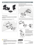
1
DTX-NSM Instruction Sheet/English Page 1 DTX-NSM Network Service Module Getting Started Guide The DTX-NSM Network Service Module lets you do the following: • Verify connection to the network, including connection speed, duplex configuration, link wiring, and PoE service (wiring and PoE functions for twisted pair only) • Ping IP addresses • Monitor network traffic for utilization, collisions, errors, and broadcast packets • Blink a port's activity LED • Use Fluke Networks LinkRunner Cable ID locators (optional) to identify link connections at a patch panel (twisted pair only) Note Running network tests on a fiber link requires an optional SFP module. Accessing the Product Manuals This guide provides basic information to help you get started using the module. For more detailed information, see the latest versions of the DTX Series Users Manual and the DTX Series Technical Reference Handbook provided on the DTX Product Manuals CD and on the Fluke Networks website. PN 2544310 (English) January 2006 2006 Fluke Corporation. All rights reserved. Printed in USA. All product names are trademarks of their respective companies. DTX-NSM Instruction Sheet/English Page 2 Software Requirements The following software supports the DTX-NSM module. Software upgrades are available on the Fluke Networks website. • DTX software: version 1.3 or later • LinkWare software: version 2.5 or later Installing the DTX-NSM Module and Optional SFP Module Install the network module only on the main tester. Install an optional SFP (small form pluggable) module to test fiber links. You may install or remove the SFP module while the tester is on. See Figure 1. WCaution Leave the module bay cover in place when a network module is not installed. Put the dust cap on the SFP port when an optical module is not installed. Put the dust cap on the optical module when not connected to a fiber. can01.eps Figure 1. Installation DTX-NSM Instruction Sheet/English Page 3 Verifying Network Connectivity The network connectivity test tells you if a network jack is connected to the switch or hub. The test also provides details about the link's configuration and includes a ping function for verifying connectivity to stations on the network. Setting Up for the Connectivity Test 1 Turn the rotary switch to SETUP, select Network Settings > IP Address Assignment; then select one of the following: • Select DHCP to have the network's server assign IP addresses. • Select Static to assign addresses manually. In Static mode, a second tab appears on the Network Settings screen. On this tab, enter the DTX Address, Subnet Mask, and Gateway (optional) and DNS Server (optional) addresses. These addresses are typically available from a network installer, administrator, technician, or from network documentation. 2 Use one of the following methods to enter ping addresses (optional): • In the latest version of LinkWare software, select Utilities > DTX Utilities > Ping Target List to create and download an address list. See the LinkWare online help for details. • On the tester's Network Settings tab, select Target Addresses. Press J Create; then enter the Name and IP Address of a device you want to ping. DTX-NSM Instruction Sheet/English Page 4 Running the Connectivity Test 1 Connect to the network using a twisted pair or fiber patch cord. 2 Turn the rotary switch to MONITOR; then select Network Connectivity. 3 Press P. Figure 2 describes some of the features on the network connectivity results screen. 4 To save the results press N, then select Save Standalone Result or Add to Cable Test Result. Use the appropriate keys to create an ID for the standalone result or save the result with an existing cable test result. A Network speed, duplex mode, PoE (Power over Ethernet) status, and MDI/MDI-X status. B Select Negotiation Details for details 1 on the connection. C The addresses used and the number 2 of ping replies received: 3 : Green: Ping replies received for all requests. : Orange: At least one ping reply received. : No ping replies received, indicating a problem with the connection. 4 D Use the softkeys to run additional can03.eps connectivity tests. Figure 2. Network Connectivity Results DTX-NSM Instruction Sheet/English Page 5 Identifying Links (twisted pair only) The ID Locator function helps you quickly identify link connections at a patch panel. This function requires one or more optional Fluke Networks LinkRunner Cable ID locators. To identify a link: 1 Connect one or more cable ID locators to one end of the link(s). 2 Turn the rotary switch to MONITOR, select ID Locator; then press P. 3 Connect the tester to different jacks, pressing P to rescan each time, until Found Cable ID and the identifier's number appears. Registration Registering your product with Fluke Networks gives you access to valuable information on product updates, troubleshooting tips, and other support services. To register, fill out the online registration form on the Fluke Networks website at www.flukenetworks.com/registration. Contacting Fluke Networks www.flukenetworks.com [email protected] +1-425-446-4519 or 1-800-283-5853 • Australia: 61 (2) 8850-3333 or 61 (3) 9329 0244 • Beijing: 86 (10) 6512-3435 • Brazil: 11 3044 1277 • Canada: 1-800-363-5853 • Europe: +44-(0)1923-281-300 • Hong Kong: 852 2721-3228 • Japan: 03-3434-0510 • Korea: 82 2 539-6311 • Singapore: 65-6799-5566 • Taiwan: (886) 2-227-83199 Visit our website for a complete list of phone numbers. DTX-NSM Instruction Sheet/English Page 6 LIMITED WARRANTY AND LIMITATION OF LIABILITY Fluke Networks mainframe products will be free from defects in material and workmanship for one year from the date of purchase. Parts, accessories, product repairs and services are warranted for 90 days, unless otherwise stated. Ni-Cad, Ni-MH and Li-Ion batteries, cables or other peripherals are all considered parts or accessories. This warranty does not cover damage from accident, neglect, misuse, alteration, contamination, or abnormal conditions of operation or handling. Resellers are not authorized to extend any other warranty on Fluke Networks’ behalf. To obtain service during the warranty period, contact your nearest Fluke Networks authorized service center to obtain return authorization information, then send your defective product to that Service Center with a description of the problem. THIS WARRANTY IS YOUR ONLY REMEDY. NO OTHER WARRANTIES, SUCH AS FITNESS FOR A PARTICULAR PURPOSE, ARE EXPRESSED OR IMPLIED. FLUKE NETWORKS IS NOT LIABLE FOR ANY SPECIAL, INDIRECT, INCIDENTAL OR CONSEQUENTIAL DAMAGES OR LOSSES, ARISING FROM ANY CAUSE OR THEORY. Since some states or countries do not allow the exclusion or limitation of an implied warranty or of incidental or consequential damages, this limitation of liability may not apply to you. Fluke Networks PO Box 777 Everett, WA 98206-0777 USA 4/04