1
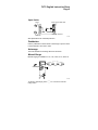
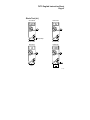
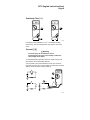
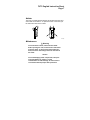
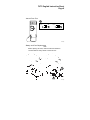
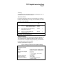
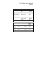
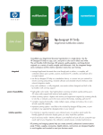
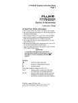
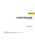
70/73 English Instruction Sheet Page 1 ® 70/73 Series III Multimeter Instruction Sheet W Read First: Safety Information To ensure that the meter is used safely, follow these instructions: • Never use the meter if the meter or test leads look damaged. • Be sure the test leads and rotary switch are in the correct position for the desired measurement. • Never measure resistance in a circuit when power is applied. • Never touch the probes to a voltage source when the test leads are plugged into the 10 A or 300 mA input jack. • To avoid damage or injury, never use the meter on circuits that exceed 4800 volt-amps. • Never apply more than the rated voltage between any input jack and earth ground. • Be careful when working with voltages above 60 V dc or 30 V ac rms. Such voltages pose a shock hazard. • Keep your fingers behind the finger guards on the test probes when making measurements. Warning To avoid false readings, which could lead to possible electric shock or personal injury, replace the battery as soon as the battery indicator (N) appears. Symbols W Z T Read First: Safety Information CAT II Overvoltage Installation Category per IEC 1010-1. Typical CAT II locations include main wall outlets, local appliances, and portable equipment. PN 650454 Manual Range or Automatic Touch Hold mode Double Insulation August 1997 Rev.2, 2/98 1997, 1998 Fluke Corporation. All rights reserved. Printed in U.S.A. All product names are trademarks of their respective companies. 70/73 English Instruction Sheet Page 2 Input Jacks Amps Volts, Ohms, Diode Test 70 V 10A ! 600V 300 mA COM FUSED 70 Common Terminal Milliamps hr2f.eps See Specifications for overload protection. Pushbutton Use the pushbutton to either select a fixed range or put the meter in the Automatic Touch Hold mode. Autorange The meter defaults to autorange when first turned on. Manual Range Manual ranging is available in V ac, V dc, ohms, A ac, and A dc. Momentary V + _ hr14f.eps To return to autorange, press R for 1 second or turn the rotary switch. 70/73 English Instruction Sheet Page 3 Automatic Touch Hold Mode W Warning To avoid electric shock, do not use the Touch Hold to determine if a circuit with high voltage is dead. The Touch Hold mode will not capture unstable or noisy readings. The Touch Hold mode automatically captures and displays stable readings. Press R for 2 seconds while turning the meter on. H V DC V DC V DC V V V 2 seconds + _ _ + _ single beep hr3f.eps When the meter captures a new input, it beeps and a new reading is displayed. To manually force a new measurement to be held, press R. Note Stray voltages can produce a new reading. To exit the Touch Hold mode, turn the meter off. Bar Graph The bar graph shows readings relative to the full scale value of a displayed measurement range and indicates polarity. hr16f.eps 70/73 English Instruction Sheet Page 4 Standby If the meter is on but is inactive for an hour (20 minutes in diode test), the screen goes blank and displays selected bar graph segments. To resume operation, turn the rotary switch or press R. AC and DC Voltage (K L mL) Volts AC Volts DC V AC Millivolts DC V DC V V + _ _ + mV + _ hr4f.eps Resistance (e) Turn off the power and discharge all capacitors. An external voltage across a component will give invalid resistance readings. k + _ hr6f.eps 70/73 English Instruction Sheet Page 5 Diode Test (G) Good Diode Good Diode _ + _ + Single Beep Forward Bias Reverse Bias Bad Diode Bad Diode _ + _ + or Open Shorted hr7f.eps 70/73 English Instruction Sheet Page 6 Continuity Test ( R ) _ + _ + hr5f.eps If continuity exists (resistance < 210 Ω), the beeper sounds continuously. The meter beeps twice if it is in the Touch Hold mode. Current (? A) W Warning To avoid injury, do not attempt a current measurement if the open circuit voltage is above the rated voltage of the meter. To avoid blowing an input fuse, use the 10 A jack until you are sure that the current is less than 300 mA. Turn off power to the circuit. Break the circuit. (For circuits of more than 10 amps, use a current clamp.) Put the meter in series with the circuit as shown and turn power on. DC 1 70 A V + 4 2 _ 3 hr8f.eps 70/73 English Instruction Sheet Page 7 Holster The snap-on holster absorbs shocks and protects the meter and comes with a Flex-Stand. To protect the front of the meter, put the meter face down in the holster. hr15f.eps Maintenance W Warning To avoid electric shock, remove the test leads before opening the case, and close the case before using the meter. To prevent fire and possible arcflash, use fuses with ratings shown on the back of the meter. Caution To avoid damaging meter components, lift up the end of the battery as shown. To avoid contamination or static damage, do not touch the circuit board without proper static protection. 70/73 English Instruction Sheet Page 8 Internal Fuse Test 70 10 A 300 mA 5-8 Ω <0.5 Ω OK OK OK OK hr10f.eps Battery and Fuse Replacement Note Before opening the case, make sure the test leads are removed and the rotary switch is turned to OFF. 70 F1 F2 hr11f.eps 70/73 English Instruction Sheet Page 9 Cleaning To clean the meter, use a damp cloth and mild detergent; do not use abrasives or solvents on the meter. Service and Parts For service information in the U.S.A. and Canada, call 1-800-44FLUKE (1-800-443-5853), in Europe, 31 40 267 8200, from other countries, 1-425-356-5500. Item Description Fluke PN Quan. BT1 Battery, 9 V, NEDA 1604/IEC 6F22, or NEDA 1604A/IEC 6LR61 696534 614487 1 F1* Fuse, F630 mA, 250 V, Min Interrupt Rating 1500 A, IEC 127-1 740670 1 F2* Fuse, F11 A, 1000 VAC/DC, Min Interrupt Rating 17 kA 943118 1 * For safety, use exact replacement Specifications Accuracy is specified for a period of one year after calibration, at 18°C to 28°C (64°F to 82°F) with relative humidity to 90%. AC conversions are ac-coupled, average responding, and calibrated to the RMS value of a sine wave input. Accuracy specifications are given as: ±([% of reading] + [number of least significant digits]) Maximum Voltage Between any Terminal and Earth Ground Display Response Time of Digital Display Operating Temperature Storage Temperature Temperature Coefficient 600 V Digital: 3,200 counts, updates 2.5/sec Analog: 31 segments, updates 25/sec V ac < 2 s V dc < 1 s Ω < 1 s to 320 kΩ, < 2s to 3.2 MΩ, < 10 s to 32 MΩ 0°C to 50°C -40°C to 60°C 0.1 x (specified accuracy)/°C (<18°C or >28°C) 70/73 English Instruction Sheet Page 10 Electromagnetic Compatibility in RF field of 3 V/m on all functions except MΩ Total accuracy = Specified accuracy plus +2.0% of range for all functions except: 320.0 mV range: total accuracy = specified accuracy + 1.0% of range 320.0Ω range: total accuracy = specified accuracy + 8% of range Relative Humidity except 32 MΩ Range: 32 MΩ Range only: Altitude Battery Type Battery Life Continuity Beeper Shock, Vibration Size (H x W x L) Weight Safety EMC Regulations Certifications/Listings 0% to 90% (0°C to 35°C) 0% to 70% (35°C to 50°C) 0% to 80% (0°C to 35°C) 0% to 70% (35°C to 50°C) Operating: 2000 meters Storage: 12,000 meters 9 V, NEDA 1604 or 6F22 or 006P, or NEDA 1604A or 6LR61 2000 hrs typical with alkaline 1600 hrs typical with carbon zinc 4096 Hz per MIL-T-PRF 28800F Class III, Sinusoidal, Non Operating 2.8 cm x 7.5 cm x 16.6 cm (1.12 in x 2.95 in x 6.55 in) 340 g (12.0 oz) 600 V CAT II per ANSI/ISA S82.011994, EN 61010-1: 1993, CSA C22.2 No 1010.1-92, UL 3111-1. EN 61326-1: 1997 70/73 English Instruction Sheet Page 11 Function Range 0L 3.200 V, 32.00 V, 320.0 V 600 V ±(0.3%+1) ±(0.4%+1) mL 320.0 mV ±(0.3%+1) K (45 to 500 Hz, 3.2V 3.200 V, 32.00 V, 320.0 V, 600 V ±(2%+2) ±(2%+2) 320.0 Ω 3200 Ω, 32.00 kΩ, 320.0 kΩ, 3.200 MΩ 32.00 MΩ ±(0.5%+2) ±(0.5%+1) ±(0.5%+1) ±(2%+1) 2.0 V ±(1% typical) range. Other ranges 45 to 1 kHz) e GR Function Range ? (45 Hz to 1 kHz) (73 only) A (73 only) Accuracy Accuracy Typical Burden Voltage 32.00 mA, 320.0 mA 10.00 A * ±(2.5%+2) ±(2.5%+2) 6 mV/mA 50 mV/A 32.00 mA, 320.0 mA 10.00 A * ±(1.5%+2) ±(1.5%+2) 6 mV/mA 50 mV/A * 10 A continuous, 20 A for 30 seconds maximum. 70/73 English Instruction Sheet Page 12 Overload protection for all functions and ranges: 600 V. Function L, mL, K Input Impedance (Nominal) >10 MΩ, <50 pF Common Mode Rejection Ratio (1 kΩ Unbalanced) L, mL K >120 dB at dc, 50 Hz, or 60 Hz GR >60 dB at 50 Hz or 60 Hz >60 dB dc to 60 Hz Open Circuit Test Voltage e Normal Mode Rejection <3.1 V dc <2.8 V dc (typical) Full Scale Voltage To 3.2 MΩ <440 mV dc <420 mV dc (typical) <3.1 V dc 32 MΩ <1.4 V dc <1.3 V dc (typical) 2.0 V dc Typical Short Circuit Current e 400 µA GR 500 µA G VF 0.0 V 0.6 V 1.2 V 2.0 V Typical Test Current 0.5 mA 0.4 mA 0.3 mA 0.1 mA