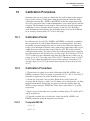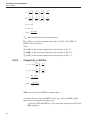
1
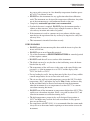
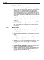
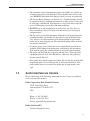
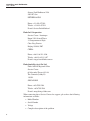
Hart Scientific
9140
Dry-well Calibrator
User’s Guide
Rev. 5B1702
Fluke Corporation, Hart Scientific Division
799 E. Utah Valley Drive • American Fork, UT 84003-9775 • USA
Phone: +1.801.763.1600 • Telefax: +1.801.763.1010
E-mail: [email protected]
www.hartscientific.com
Subject to change without notice. • Copyright © 2005 • Printed in USA
Rev. 5B1702
Table of Contents
1 Before You Start . . . . . . . . . . . . . . . . . . . . . . . . . . 1
1.1
1.2
Symbols Used . . . . . . . . . . . . . . . . . . . . . . . . . . . . 1
Safety Information . . . . . . . . . . . . . . . . . . . . . . . . . . 2
1.2.1
1.2.2
1.3
WARNINGS . . . . . . . . . . . . . . . . . . . . . . . . . . . . . . . . . . . 2
CAUTIONS . . . . . . . . . . . . . . . . . . . . . . . . . . . . . . . . . . . 4
Authorized Service Centers. . . . . . . . . . . . . . . . . . . . . . 5
2 Introduction . . . . . . . . . . . . . . . . . . . . . . . . . . . . 7
3 Specifications and Environmental Conditions . . . . . . . . . . 9
3.1
3.2
Specifications . . . . . . . . . . . . . . . . . . . . . . . . . . . . . 9
Environmental Conditions . . . . . . . . . . . . . . . . . . . . . . 9
3.3
Warranty . . . . . . . . . . . . . . . . . . . . . . . . . . . . . . . 10
4 Quick Start . . . . . . . . . . . . . . . . . . . . . . . . . . . . 11
4.1
4.2
Unpacking . . . . . . . . . . . . . . . . . . . . . . . . . . . . . . 11
Set-Up . . . . . . . . . . . . . . . . . . . . . . . . . . . . . . . . 11
4.3
4.4
Power . . . . . . . . . . . . . . . . . . . . . . . . . . . . . . . . 11
Setting the Temperature . . . . . . . . . . . . . . . . . . . . . . . 12
5 Parts and Controls . . . . . . . . . . . . . . . . . . . . . . . . 13
5.1
Rear Panel . . . . . . . . . . . . . . . . . . . . . . . . . . . . . . 13
5.2
5.3
Front Panel . . . . . . . . . . . . . . . . . . . . . . . . . . . . . 14
Constant Temperature Block Assembly . . . . . . . . . . . . . . . 15
5.3.1
5.3.2
Constant Temperature Block . . . . . . . . . . . . . . . . . . . . . . . . . . 15
Probe Sleeves and Tongs . . . . . . . . . . . . . . . . . . . . . . . . . . . . 15
6 General Operation . . . . . . . . . . . . . . . . . . . . . . . . 17
6.1
6.2
6.3
6.4
6.5
Calibrator Set-Up . . . . . . .
Changing Display Units . . . .
Switching to 230 V Operation.
Setting the Temperature . . . .
Calibrating Probes . . . . . . .
.
.
.
.
.
.
.
.
.
.
.
.
.
.
.
.
.
.
.
.
.
.
.
.
.
.
.
.
.
.
.
.
.
.
.
.
.
.
.
.
.
.
.
.
.
.
.
.
.
.
.
.
.
.
.
.
.
.
.
.
.
.
.
.
.
.
.
.
.
.
.
.
.
.
.
.
.
.
.
.
.
.
.
.
.
.
.
.
.
.
.
.
.
.
.
17
17
17
18
18
7 Controller Operation . . . . . . . . . . . . . . . . . . . . . . . 21
7.1
Well Temperature . . . . . . . . . . . . . . . . . . . . . . . . . . 21
i
7.2
Temperature Set-point . . . . . . . . . . . . . . . . . . . . . . . . 21
7.2.1
7.2.2
7.2.3
7.3
Scan . . . . . . . . . . . . . . . . . . . . . . . . . . . . . . . . . 24
7.3.1
7.3.2
7.4
Hold Temperature Display
Mode Setting . . . . . . .
Switch Wiring . . . . . . .
Switch Test Example . . .
.
.
.
.
.
.
.
.
.
.
.
.
.
.
.
.
.
.
.
.
.
.
.
.
.
.
.
.
.
.
.
.
.
.
.
.
.
.
.
.
.
.
.
.
.
.
.
.
.
.
.
.
.
.
.
.
.
.
.
.
.
.
.
.
.
.
.
.
.
.
.
.
.
.
.
.
.
.
.
.
.
.
.
.
.
.
.
.
.
.
.
.
.
.
.
.
.
.
.
.
.
.
.
.
25
25
25
26
Heater Power . . . . . . . . . . . . . . . . . . . . . . . . . . . . . . . . . . 26
Proportional Band. . . . . . . . . . . . . . . . . . . . . . . . . . . . . . . . 27
Controller Configuration . . . . . . . . . . . . . . . . . . . . . . 29
7.6.1
Calibration Parameters . . . . . . . . . . . . . . . . . . . . . . . . . . . . . 29
7.6.1.1
7.6.1.2
7.6.1.3
7.7
7.8
.
.
.
.
Secondary Menu. . . . . . . . . . . . . . . . . . . . . . . . . . . 26
7.5.1
7.5.2
7.6
Scan Control . . . . . . . . . . . . . . . . . . . . . . . . . . . . . . . . . . 24
Scan Rate . . . . . . . . . . . . . . . . . . . . . . . . . . . . . . . . . . . . 24
Temperature Display Hold . . . . . . . . . . . . . . . . . . . . . 25
7.4.1
7.4.2
7.4.3
7.4.4
7.5
Programmable Set-points . . . . . . . . . . . . . . . . . . . . . . . . . . . . 21
Set-point Value . . . . . . . . . . . . . . . . . . . . . . . . . . . . . . . . . 23
Temperature Scale Units . . . . . . . . . . . . . . . . . . . . . . . . . . . . 23
R0 . . . . . . . . . . . . . . . . . . . . . . . . . . . . . . . . . . . . . . . . . . . . 29
ALPHA . . . . . . . . . . . . . . . . . . . . . . . . . . . . . . . . . . . . . . . . . 30
DELTA . . . . . . . . . . . . . . . . . . . . . . . . . . . . . . . . . . . . . . . . . 30
Operating Parameters . . . . . . . . . . . . . . . . . . . . . . . . 30
Serial Interface Parameters . . . . . . . . . . . . . . . . . . . . . 30
7.8.0.1
7.8.1
Baud Rate . . . . . . . . . . . . . . . . . . . . . . . . . . . . . . . . . . . . . . . . 30
Sample Period. . . . . . . . . . . . . . . . . . . . . . . . . . . . . . . . . . 31
7.8.1.1
7.8.1.2
Duplex Mode . . . . . . . . . . . . . . . . . . . . . . . . . . . . . . . . . . . . . . 31
Linefeed . . . . . . . . . . . . . . . . . . . . . . . . . . . . . . . . . . . . . . . . . 32
8 Digital Communication Interface . . . . . . . . . . . . . . . . 33
8.1
Serial Communications . . . . . . . . . . . . . . . . . . . . . . . 33
8.1.1
8.1.2
Wiring . . . . . . . . . . . . . . . . . . . . . . . . . . . . . . . . . . . . . . 33
Setup . . . . . . . . . . . . . . . . . . . . . . . . . . . . . . . . . . . . . . 33
8.1.2.1
8.1.2.2
8.1.2.3
8.1.2.4
8.1.3
8.2
Baud Rate . . .
Sample Period.
Duplex Mode .
Linefeed . . . .
.
.
.
.
.
.
.
.
.
.
.
.
.
.
.
.
.
.
.
.
.
.
.
.
.
.
.
.
.
.
.
.
.
.
.
.
.
.
.
.
.
.
.
.
.
.
.
.
.
.
.
.
.
.
.
.
.
.
.
.
.
.
.
.
.
.
.
.
.
.
.
.
.
.
.
.
.
.
.
.
.
.
.
.
.
.
.
.
.
.
.
.
.
.
.
.
.
.
.
.
.
.
.
.
.
.
.
.
.
.
.
.
.
.
.
.
.
.
.
.
.
.
.
.
.
.
.
.
.
.
.
.
.
.
.
.
.
.
.
.
.
.
.
.
. 34
. 34
. 34
. 34
Serial Operation . . . . . . . . . . . . . . . . . . . . . . . . . . . . . . . . . 34
Interface Commands . . . . . . . . . . . . . . . . . . . . . . . . 35
9 Test Probe Calibration . . . . . . . . . . . . . . . . . . . . . . 39
9.1
Comparison Methods . . . . . . . . . . . . . . . . . . . . . . . . 39
9.1.1
9.1.2
9.1.3
9.2
Dry-well Characteristics. . . . . . . . . . . . . . . . . . . . . . . 40
9.2.1
9.2.2
9.2.3
ii
Calibrating a Single Probe . . . . . . . . . . . . . . . . . . . . . . . . . . . 39
Comparison Calibration. . . . . . . . . . . . . . . . . . . . . . . . . . . . . 39
Calibration of Multiple Probes . . . . . . . . . . . . . . . . . . . . . . . . . 40
Vertical Gradient . . . . . . . . . . . . . . . . . . . . . . . . . . . . . . . . 40
Heating and Cooling Rates . . . . . . . . . . . . . . . . . . . . . . . . . . . 40
Stabilization and Accuracy . . . . . . . . . . . . . . . . . . . . . . . . . . . 41
10 Calibration Procedure . . . . . . . . . . . . . . . . . . . . . . 43
10.1 Calibration Points . . . . . . . . . . . . . . . . . . . . . . . . . . 43
10.2 Calibration Procedure . . . . . . . . . . . . . . . . . . . . . . . . 43
10.2.1
10.2.2
10.2.3
Compute DELTA: . . . . . . . . . . . . . . . . . . . . . . . . . . . . . . . . 43
Compute R & ALPHA: . . . . . . . . . . . . . . . . . . . . . . . . . . . . . 44
Accuracy & Repeatability. . . . . . . . . . . . . . . . . . . . . . . . . . . . 45
0
11 Maintenance . . . . . . . . . . . . . . . . . . . . . . . . . . . 47
12 Troubleshooting. . . . . . . . . . . . . . . . . . . . . . . . . . 49
12.1 Troubleshooting Problems, Possible Causes, and Solutions . . . . 49
12.2 CE Comments . . . . . . . . . . . . . . . . . . . . . . . . . . . . 50
12.2.1
12.2.2
EMC Directive . . . . . . . . . . . . . . . . . . . . . . . . . . . . . . . . . 50
Low Voltage Directive (Safety) . . . . . . . . . . . . . . . . . . . . . . . . . 50
iii
Figures
Figure 1
Figure 2
Figure 3
Figure 4
Figure 5
Figure 6
Figure 7
Figure 8
iv
9140 Back Panel . . . . . . . . . . . . . . . . . . . . . . . . . . .
9140 Front Panel . . . . . . . . . . . . . . . . . . . . . . . . . . .
Inserts available for the 9140 block assembly . . . . . . . . . . . .
Controller Operation Flowchart . . . . . . . . . . . . . . . . . . .
Well temperature fluctuation at various proportional band settings .
Serial Cable Wiring . . . . . . . . . . . . . . . . . . . . . . . . .
Typical Heating Rate . . . . . . . . . . . . . . . . . . . . . . . . .
Typical Cooling Rate. . . . . . . . . . . . . . . . . . . . . . . . .
.
.
.
.
.
.
.
.
.
.
.
.
.
.
.
.
13
14
15
22
27
33
41
41
Tables
Table 1
Table 2
Table 3
International Electrical Symbols . . . . . . . . . . . . . . . . . . . . . 1
9140 controller communications commands. . . . . . . . . . . . . . . 36
9140 controller communications commands continued . . . . . . . . . 37
v
1 Before You Start
Symbols Used
1
1.1
Before You Start
Symbols Used
Table 1 lists the symbols used on the instrument or in this manual and the
meaning of each symbol.
Table 1 International Electrical Symbols
Symbol
Description
AC (Alternating Current)
AC-DC
Battery
Complies with European Union directives
DC
Double Insulated
Electric Shock
Fuse
PE Ground
Hot Surface (Burn Hazard)
Read the User’s Manual (Important Information)
Off
On
1
9140 Dry-well Calibrator
User’s Guide
Symbol
Description
Canadian Standards Association
OVERVOLTAGE (Installation) CATEGORY II, Pollution Degree 2 per IEC1010-1 refers to the level of Impulse Withstand Voltage protection provided. Equipment of
OVERVOLTAGE CATEGORY II is energy-consuming equipment to be supplied from
the fixed installation. Examples include household, office, and laboratory appliances.
C-TIC Australian EMC
The European Waste Electrical and Electronic Equipment (WEEE) Directive
(2002/96/EC) mark.
1.2
Safety Information
Use the instrument only as specified in this manual. Otherwise, the protection
provided by the instrument may be impaired. Refer to the safety information
below and throughout the manual.
The following definitions apply to the terms “Warning” and “Caution”.
• “Warning” identifies conditions and actions that may pose hazards to the
user.
• “Caution” identifies conditions and actions that may damage the instrument being used.
1.2.1
WARNINGS
To avoid personal injury, follow these guidelines.
GENERAL
• DO NOT use this instrument in environments other than those listed in
the User’s Guide.
• Inspect the instrument for damage before each use. DO NOT use the instrument if it appears damaged or operates abnormally.
• Follow all safety guidelines listed in the user’s manual.
• Calibration Equipment should only be used by Trained Personnel.
• If this equipment is used in a manner not specified by the manufacturer,
the protection provided by the equipment may be impaired.
• Before initial use, or after transport, or after storage in humid or semi-humid environments, or anytime the dry-well has not been energized for
more than 10 days, the instrument needs to be energized for a "dry-out"
period of 2 hours before it can be assumed to meet all of the safety requirements of the IEC 1010-1. If the product is wet or has been in a wet
environment, take necessary measures to remove moisture prior to apply-
2
1 Before You Start
Safety Information
ing power such as storage in a low humidity temperature chamber operating at 50°C for 4 hours or more.
• DO NOT use this instrument for any application other than calibration
work. The instrument was designed for temperature calibration. Any other
use of the instrument may cause unknown hazards to the user.
• Completely unattended operation is not recommended.
• Overhead clearance is required. DO NOT place the instrument under a
cabinet or other structure. Always leave enough clearance to allow for
safe and easy insertion and removal of probes.
• If the instrument is used in a manner not in accordance with the equipment design, the operation of the dry-well may be impaired or safety hazards may arise.
• This instrument is intended for indoor use only.
BURN HAZARDS
• DO NOT turn the instrument upside down with the inserts in place; the
inserts will fall out.
• DO NOT operate near flammable materials.
• Use of this instrument at HIGH TEMPERATURES for extended periods
of time requires caution.
• DO NOT touch the well access surface of the instrument.
• The block vent may be very hot due to the fan blowing across the heater
block of the dry-well.
• The temperature of the well access is the same as the actual display temperature, e.g. if the instrument is set to 700°C and the display reads
700°C, the well is at 700°C.
• For top loading dry-wells, the top sheet metal of the dry-well may exhibit
extreme temperatures for areas close to the well access.
• The air over the well can reach temperatures greater that 200°C for high
temperature (400°C and higher) dry-wells. Note: Probes and inserts may
be hot and should only be inserted and removed from the instrument
when the instrument is set at temperatures less than 50°C. Use extreme
care when removing hot inserts.
• DO NOT turn off the instrument at temperatures higher than 100°C. This
could create a hazardous situation. Select a set-point less than 100°C and
allow the instrument to cool before turning it off.
• The high temperatures present in dry-wells designed for operation at
300°C and higher may result in fires and severe burns if safety precautions are not observed.
• For compliance with IEC 1010-1, it is recommended that the cutout mode
always be set to the manual mode requiring user intervention to reset the
instrument.
3
9140 Dry-well Calibrator
User’s Guide
ELECTRICAL SHOCK
• These guidelines must be followed to ensure that the safety mechanisms
in this instrument will operate properly. This instrument must be plugged
into a 115 VAC, 60Hz (230 VAC, 50Hz optional), AC only electric outlet.
The power cord of the instrument is equipped with a three-pronged
grounding plug for your protection against electrical shock hazards. It
must be plugged directly into a properly grounded three-prong receptacle.
The receptacle must be installed in accordance with local codes and ordinances. Consult a qualified electrician. DO NOT use an extension cord or
adapter plug.
• If supplied with user accessible fuses, always replace the fuse with one of
the same rating, voltage, and type.
• Always replace the power cord with an approved cord of the correct rating and type.
• HIGH VOLTAGE is used in the operation of this equipment. SEVERE
INJURY or DEATH may result if personnel fail to observe safety precautions. Before working inside the equipment, turn power off and disconnect power cord.
1.2.2
CAUTIONS
• Always operate this instrument at room temperature between 41°F and
122°F (5°C to 50°C). Allow sufficient air circulation by leaving at least 6
inches (15 cm) of clearance around the instrument. Overhead clearance is
required. DO NOT place unit under any structure.
• Component lifetime can be shortened by continuous high temperature operation.
• DO NOT leave the sleeve(s) in the instrument for prolonged periods. Due
to the high operating temperatures of the instrument, the sleeves should be
removed after each use and buffed with a Scotch-Brite® pad or emery
cloth. (See Maintenance, Section .)
• DO NOT apply any type of voltage to the display hold terminals. Applying a voltage to the terminals may cause damage to the controller.
• DO NOT use fluids to clean out the well. Fluids could leak into electronics and damage the instrument.
• Never introduce any foreign material into the probe hole of the insert.
Fluids, etc. can leak into the instrument causing damage.
• DO NOT change the values of the calibration constants from the factory
set values. The correct setting of these parameters is important to the
safety and proper operation of the calibrator.
• DO NOT slam the probe sheath in to the well. This type of action can
cause a shock to the sensor and affect the calibration.
4
1 Before You Start
Authorized Service Centers
• The instrument and any thermometer probes used with it are sensitive instruments that can be easily damaged. Always handle these devices with
care. DO NOT allow them to be dropped, struck, stressed, or overheated.
• The Factory Reset Sequence (see Section 12.1, Troubleshooting) should
be performed only by authorized personnel if no other action is successful
in correcting a malfunction. You must have a copy of the most recent Report of Calibration to restore the calibration parameters.
• DO NOT operate this instrument in an excessively wet, oily, dusty, or
dirty environment. Always keep the well and inserts clean and clear of
foreign material.
• The dry-well is a precision instrument. Although it has been designed for
optimum durability and trouble free operation, it must be handled with
care. Always carry the instrument in an upright position to prevent the
probe sleeves from dropping out. The convenient handle allows for hand
carrying the instrument.
• If a mains supply power fluctuation occurs, immediately turn off the instrument. Power bumps from brown-outs could damage the instrument.
Wait until the power has stabilized before re-energizing the instrument.
• The probe and the block may expand at different rates. Allow for probe
expansion inside the well as the block heats. Otherwise, the probe may
become stuck in the well.
• Most probes have handle temperature limits. Be sure that the probe handle
temperature limit is not exceeded in the air above the instrument. If the
probe handle limits are exceeded, the probe may be permanently damaged.
1.3
Authorized Service Centers
Please contact one of the following authorized Service Centers to coordinate
service on your Hart product:
Fluke Corporation, Hart Scientific Division
799 E. Utah Valley Drive
American Fork, UT 84003-9775
USA
Phone: +1.801.763.1600
Telefax: +1.801.763.1010
E-mail: [email protected]
Fluke Nederland B.V.
Customer Support Services
5
9140 Dry-well Calibrator
User’s Guide
Science Park Eindhoven 5108
5692 EC Son
NETHERLANDS
Phone: +31-402-675300
Telefax: +31-402-675321
E-mail: [email protected]
Fluke Int'l Corporation
Service Center - Instrimpex
Room 2301 Sciteck Tower
22 Jianguomenwai Dajie
Chao Yang District
Beijing 100004, PRC
CHINA
Phone: +86-10-6-512-3436
Telefax: +86-10-6-512-3437
E-mail: [email protected]
Fluke South East Asia Pte Ltd.
Fluke ASEAN Regional Office
Service Center
60 Alexandra Terrace #03-16
The Comtech (Lobby D)
118502
SINGAPORE
Phone: +65 6799-5588
Telefax: +65 6799-5588
E-mail: [email protected]
When contacting these Service Centers for support, please have the following
information available:
• Model Number
• Serial Number
• Voltage
• Complete description of the problem
6
2 Introduction
2
Introduction
The Hart Scientific 9140 Mid-Range Field Calibrator may be used as a portable
instrument or bench top temperature calibrator for calibrating thermocouple
and RTD temperature probes. The 9140 is small enough to use in the field, and
accurate enough to use in the lab.
The instrument features:
• Rapid heating and cooling
• Interchangeable multiple hole aluminum probe sleeves
• Convenient hand strap
• RS-232 interface capability
Built in programmable features include:
• Temperature scan rate control
• Temperature switch hold
• Eight Setpoint memory
• Adjustable readout in °C or °F
The temperature is accurately controlled by Hart’s hybrid analog/digital controller. The controller uses a precision platinum RTD as a sensor and controls
the well temperature with a solid state relay (triac) driven heater.
The LED front panel continuously shows the current well temperature. The
temperature may be easily set with the control buttons to any desired temperature within the specified range. The instrument’s multiple fault protection devices insure user and instrument safety and protection.
The 9140 dry-well calibrator was designed for portability, low cost, and ease of
operation. Through proper use the instrument will provide continued accurate
calibration of temperature sensors and devices. The user should be familiar
with the safety guidelines and operating procedures of the calibrator as described in the instruction manual.
7
3 Specifications and Environmental Conditions
Specifications
3
3.1
Specifications and Environmental
Conditions
Specifications
The following table lists the specifications for this instrument. Accuracy specifications are applicable for a one-year calibration interval. In line with normal
prudent metrology practices, Hart Scientific recommends a short-cycle interval
of six months for new units during the first year.
3.2
Power
115 VAC (±10%), 4.4 A or 230 VAC (±10%), 2.2 A, switchable 500 W
Ambient Temperature
5–50°C (41–122°F)
Operating Range
35–350°C (95–662°F)
Resolution
0.1°C or °F resolution
Readout
Switchable°C or °F
Accuracy
±0.5°C (±0.9°F), in holes greater than 1/4" (6.35 mm) accuracy is ±1°C
(±1.8°F)
Stability
±0.03°C at 50°C, ±0.05°C at 350°C
Uniformity
±0.4°C typical, ±0.1°C with similarly sized wells
Controller
Digital controller with data retention
Heater
500W
Heating Time
12 minutes from ambient to 350°C
Cooling Time
15 minutes from 350°C to 100°C
Cooling
2 speed internal fan
Stabilization Time
7 minutes
Immersion Depth
124 mm (4.88 inches)
Fault Protection
Sensor burnout and short protection, over temperature thermal cut-out, electrical fuses
Test Wells
31.8 mm dia. x 123.7 mm deep (1.25" x 4.87"). Multi-hole inserts are
available.
Exterior Dimension
152.4 mm H x 85.7 mm W x 196.9 mm D (6" x 3.375" x 7.75")
Weight
2.7 kg (6 lbs.)
Fuse Rating
115 V: 6 A (fast acting), 250 V
230 V: 3.15 A (fast acting), 250 V
Safety
OVERVOLTAGE (Installation) CATEGORY II, Pollution Degree 2 per
IEC1010-1
Environmental Conditions
Although the instrument has been designed for optimum durability and trouble-free operation, it must be handled with care. The instrument should not be
9
9140 Dry-well Calibrator
User’s Guide
operated in an excessively dusty or dirty environment. Maintenance and cleaning recommendations can be found in the Maintenance Section of this manual.
The instrument operates safely under the following conditions:
• temperature range: 5–50°C (41–122°F)
• ambient relative humidity: 15–50%
• pressure: 75kPa–106kPa
• mains voltage within ±10% of nominal
• vibrations in the calibration environment should be minimized
• altitude does not effect the performance or safety of the unit
3.3
Warranty
Fluke Corporation, Hart Scientific Division (Hart) warrants this product to be
free from defects in material and workmanship under normal use and service
for a period as stated in our current product catalog from the date of shipment.
This warranty extends only to the original purchaser and shall not apply to any
product which, in Hart’s sole opinion, has been subject to misuse, alteration,
abuse or abnormal conditions of operation or handling.
Software is warranted to operate in accordance with its programmed instructions on appropriate Hart products. It is not warranted to be error free.
Hart’s obligation under this warranty is limited to repair or replacement of a
product which is returned to Hart within the warranty period and is determined,
upon examination by Hart, to be defective. If Hart determines that the defect or
malfunction has been caused by misuse, alteration, abuse or abnormal conditions or operation or handling, Hart will repair the product and bill the purchaser for the reasonable cost of repair.
To exercise this warranty, contact an Authorized Service Center (see Section
1.3). Service Centers assume NO risk for in-transit damage.
THE FOREGOING WARRANTY IS PURCHASER’S SOLE AND EXCLUSIVE REMEDY AND IS IN LIEU OF ALL OTHER WARRANTIES, EXPRESS OR IMPLIED, INCLUDING BUT NOT LIMITED TO ANY
IMPLIED WARRANTY OR MERCHANTABILITY, OR FITNESS FOR ANY
PARTICULAR PURPOSE OR USE. HART SHALL NOT BE LIABLE FOR
ANY SPECIAL, INDIRECT, INCIDENTAL, OR CONSEQUENTIAL DAMAGES OR LOSS WHETHER IN CONTRACT, TORT, OR OTHERWISE.
10
4 Quick Start
Unpacking
4
4.1
Quick Start
Unpacking
Unpack the dry-well carefully and inspect it for any damage that may have occurred during shipment. If there is shipping damage, notify the carrier
immediately.
Verify that the following components are present:
• 9140 Dry-well
• Insert
• Insert Removal Tool
• Power Cord
• Serial Cable
• User's Guide
• 9930 Software Package
4.2
Set-Up
Place the calibrator on a flat surface with at least 6 inches of free space around
the instrument. Plug the power cord into a grounded mains outlet. Observe that
the nominal voltage corresponds to that indicated on the back of the calibrator.
Carefully insert the probe sleeve into the well. Probe sleeves should be of the
smallest hole diameter possible still allowing the probe to slide in and out easily. Sleeves of various sizes are available from Hart Scientific. The well must be
clear of any foreign objects, dirt and grit before the sleeve is inserted. The
sleeve is inserted with the two small tong holes positioned upward.
Turn on the power to the calibrator by toggling the switch on the power entry
module. The fan should begin quietly blowing air through the instrument and
the controller display should illuminate after 3 seconds. After a brief self test
the controller should begin normal operation. If the unit fails to operate please
check the power connection.
The display will begin to show the well temperature and the well heater will
start operating to bring the temperature of the well to the set-point temperature.
After using the calibrator, allow the well to cool by setting the temperature to
25°C and waiting for the instrument to reach temperature before turning the instrument off.
4.3
Power
Plug the dry-well power cord into a mains outlet of the proper voltage, frequency, and current capability. Refer to Section 3.1, Specifications, for power
details. Turn the dry-well on using the rear panel “POWER” switch. The
11
9140 Dry-well Calibrator
User’s Guide
dry-well will turn on and begin to heat to the previously programmed temperature set-point. The front panel LED display will indicate the actual dry-well
temperature.
4.4
Setting the Temperature
Section 7.2 explains in detail how to set the temperature set-point on the calibrator using the front panel keys. The procedure is summarized here.
(1) Press “SET” twice to access the set-point value.
(2) Press “UP” or “DOWN” to change the set-point value.
(3) Press “SET” to program in the new set-point.
(4) Press “EXIT” to return to the temperature display.
When the set-point temperature is changed the controller will switch the well
heater on or off to raise or lower the temperature. The displayed well temperature will gradually change until it reaches the set-point temperature. The well
may require 5 to 10 minutes to reach the set-point depending on the span. Another 5 to 10 minutes is required to stabilize within ±0.1°C of the set-point. Ultimate stability may take 15 to 20 minutes more of stabilization time.
12
5 Parts and Controls
Rear Panel
5
Parts and Controls
The user should become familiar with the dry-well calibrator and its parts:
5.1
Rear Panel
Figure 1 on page 13.
Power Cord - At the rear of the calibrator is the removable power cord inlet
that plugs into an IEC grounded socket.
Power Switch - The power switch is located on the power entry module
(PEM). The PEM also houses the fuses and the dual voltage selector. The PEM
and Heater Voltage Switch (see below) allow the unit to be field switchable for
115 VAC (±10%) or 230 VAC (±10%) operation.
Heater Voltage Switch - To be used only when changing the input voltage.
(See Section 6.3 for instructions on changing the input voltage.)
Note: The input voltage and heater voltage switch settings should always be the
same value.
Serial Port - A DB-9 male connector is present for interfacing the calibrator to
a computer or terminal with serial RS-232 communications.
Fan - The fan inside the calibrator runs continuously when the unit is being operated to provide cooling for the instrument. It has two speeds, a slow speed for
control operation and a faster speed for rapid cooling. Slots at the top and
Figure 1 9140 Back Panel
13
9140 Dry-well Calibrator
User’s Guide
around the two corners of the calibrator are provided for airflow. The area
around the calibrator must be kept clear to allow adequate ventilation. The airflow is directed upward and as a result, can be extremely hot.
5.2
Front Panel
Figure 2 on page 14.
Controller Display - The digital display is an important part of the temperature
controller because it not only displays set and actual temperatures but also various calibrator functions, settings, and constants. The display shows temperatures in units according to the selected scale °C or °F.
Controller Keypad - The four button keypad allows easy setting of the
set-point temperature. The control buttons (SET, DOWN, UP, and EXIT) are
used to set the calibrator temperature set-point, access and set other operating
parameters, and access and set calibration parameters.
Setting the control temperature is done directly in degrees of the current scale.
It can be set to one-tenth of a degree Celsius or Fahrenheit.
The functions of the buttons are as follows:
SET – Used to display the next parameter in the menu and to store parameters
to the displayed value.
DOWN – Used to decrement the displayed value of parameters.
UP – Used to increment the displayed value.
Figure 2 9140 Front Panel
14
5 Parts and Controls
Constant Temperature Block Assembly
EXIT – Used to exit a function and to skip to the next function. Any changes
made to the displayed value are ignored.
5.3
Constant Temperature Block Assembly
Figure 3 on page 15.
5.3.1
Constant Temperature Block
The “Block” is made of aluminum and provides a relatively constant and accurate temperature environment in which the sensor that is to be calibrated is inserted. A 1.25 inch diameter well is provided that may be used for sensors of
that size or may be sleeved down with various sized multi-hole probe sleeves.
Heaters surround the block assembly and provides even heat to the sensor. A
high-temperature platinum RTD is imbedded at the base of the block assembly
to sense and control the temperature of the block. The entire assembly is suspended in an air cooled chamber thermally isolated from the chassis and
electronics.
CAUTION: The block vent cover may be very hot due to the fan blowing
upward. Please use caution.
5.3.2
Probe Sleeves and Tongs
The calibrator is supplied with a multi-hole aluminum probe sleeve for insertion into the calibrator well and tongs for removing sleeves. Probe sleeves of
various hole sizes are available to allow the user’s probe to fit snugly into the
well whatever the diameter of the probe.
One insert, whichever is ordered, is shipped with the unit:
• Insert A (variety block): 1/2”, 3/8”,3/16”,1/8”, and 1/16” holes
• Insert B (comparison block): 2 3/8”,2 1/4”, and 2 3/16” holes
• Insert C (1/4” comparison block): 6 1/4” holes
or
1/16"
1/2"
Insert “A”
Insert “B”
1/4"
3/16"
3/8"
1/4"
1/4"
3/8"
3/8"
Insert “C”
3 mm
Insert “D”
4 mm
6 mm
6 mm
1/8"
3/16"
1/4"
3/16"
4 mm
3 mm
Figure 3 Inserts available for the 9140 block assembly
15
9140 Dry-well Calibrator
User’s Guide
• Insert D (comparison block): 2 each at 3 mm, 4 mm, and 6 mm
16
6 General Operation
Calibrator Set-Up
6
6.1
General Operation
Calibrator Set-Up
Place the calibrator on a flat surface with at least 6 inches of free space around
the instrument. Overhead clearance is required. DO NOT place under a cabinet
or other structure.Plug the power cord into a grounded mains outlet. Observe
that the nominal voltage corresponds to that indicated on the back of the
calibrator.
Gently insert the probe sleeve into the well. The probe sleeve should be of the
smallest hole size possible while allowing the probe to slide in and out easily.
Sleeves of various sizes are available from the manufacturer. The well must be
clear of any foreign objects, dirt and grit before the sleeve is inserted. The
sleeve is inserted with the two small tong holes positioned upward.
Turn on the power to the calibrator by toggling the switch at the rear of the instrument to the “l” (on) position. The fan will begin circulating air through the
instrument. After a brief self test the controller should begin normal operation
showing the well temperature. The block will heat or cool until it reaches the
programmed set-point.
6.2
Changing Display Units
The 9140 can display temperature in Celsius or Fahrenheit. The temperature
units are shipped from the factory set to Celsius. To change to Fahrenheit or
back to Celsius there are two ways:
1 - Press the “SET” and “UP” simultaneously. This will change display units.
2 - Press the “SET” key three times from the temperature display to show
Un= C
Press the “UP” or “DOWN” key to change units.
6.3
Switching to 230 V Operation
The 9140 is switchable from 115 VAC to 230 VAC 50/60 Hz. Switching the
voltage can change the calibration, so it is recommended to recalibrate the unit
after changing the input voltage.
To change from 115 VAC to 230 VAC:
• Unplug the unit
• With a small straight slot screwdriver remove the fuse holder located on
the rear panel. Replace the two 6 amps fuses with 3 amp 250 V fuses.
• Replace the fuse holder with the “230V” in the display window.
17
9140 Dry-well Calibrator
User’s Guide
• Using the same straight slot screwdriver, move the heater switch to display “230V”. See the rear panel drawing in Figure 1 on page 13.
NOTE: If the heater switch and the fuse holder do not both read 230V when
complete, the unit will either not heat or only heat at a fraction of its capacity.
If not done properly, the unit could become damaged and void the calibration
and warranty.
CAUTION: DO NOT plug the unit into 230 V if the heater switch and fuse
holder read 115. This will cause the fuse to blow and may damage the instrument.
6.4
Setting the Temperature
Section 7.2 explains in detail how to set the temperature set-point on the calibrator using the front panel keys. The procedure is summarized here.
(1) Press “SET” twice to access the set-point value.
(2) Press “UP” or “DOWN” to change the set-point value.
(3) Press “SET” to program in the new set-point.
(4) Press “EXIT” to return to the temperature display.
When the set-point temperature is changed the controller will switch the well
heater on or off to raise or lower the temperature. The cycle indicator, a two
color LED, will also indicate on (red and heating) or off (green and cooling).
The displayed well temperature will gradually change until it reaches the
set-point temperature. The well may require 5 to 20 minutes to reach the
set-point depending on the span. Another 5 to 10 minutes is required for the
temperature to stabilize.
6.5
Calibrating Probes
The dry-well block provides a constant temperature environment in which
probes may be compared. The probes inserted into the block may be compared
to the well temperature displayed on the front panel of the calibrator. The
probes should be inserted the full depth of the well since the temperature at the
bottom of the well will most closely agree with the displayed temperature.
For greater accuracy the probes may be compared to a reference thermometer
inserted into the block. The reference thermometer may be inserted into one
hole while the probes to be calibrated are inserted into another. The drawback
to this method is that because of temperature variations throughout the block
there may be a small temperature difference between one hole and another
which can cause errors.
18
6 General Operation
Calibrating Probes
Using the same hole for the reference thermometer and the test probe may have
better results. This however requires switching the probes which takes more
time. One must allow a few minutes after inserting the probes for the temperature to stabilize before making measurements. Because of temperature variations along the length of the well, best results are obtained when comparing
probes of similar construction and inserting them the same depth into the well.
19
7 Controller Operation
Well Temperature
7
Controller Operation
This chapter discusses in detail how to operate the dry-well temperature controller using the front control panel. Using the front panel key-switches and
LED display the user may monitor the well temperature, set the temperature
set-point in degrees C or F, monitor the heater output power, adjust the controller proportional band, and program the calibration parameters, operating parameters, and serial interface configuration. Operation of the functions and
parameters are shown in the flowchart in Figure 4 on page 22. This chart may
be copied for reference.
In the following discussion a button with the word SET, UP, EXIT or DOWN
inside indicates the panel button while the dotted box indicates the display
reading. Explanation of the button or display reading are to the right of each
button or display value.
7.1
Well Temperature
The digital LED display on the front panel allows direct viewing of the actual
well temperature. This temperature value is what is normally shown on the display. The units, C or F, of the temperature value are displayed at the right. For
example,
100.0 C
Well temperature in degrees Celsius
The temperature display function may be accessed from any other function by
pressing the “EXIT” button.
7.2
Temperature Set-point
The temperature set-point can be set to any value within the range and with resolution as given in the specifications. Be careful not to exceed the safe upper
temperature limit of any device inserted into the well.
Setting the temperature involves two steps: (1) select the set-point memory and
(2) adjust the set-point value.
7.2.1
Programmable Set-points
The controller stores 8 set-point temperatures in memory. The set-points can be
quickly recalled to conveniently set the calibrator to a previously programmed
temperature set-point.
To set the temperature one must first select the set-point memory. This function
is accessed from the temperature display function by pressing “SET”. The
number of the set-point memory currently being used is shown at the left on the
display followed by the current set-point value.
21
9140 Dry-well Calibrator
User’s Guide
Figure 4 Controller Operation Flowchart
22
7 Controller Operation
Temperature Set-point
100.0 C
S
Well temperature in degrees Celsius
Access set-point memory
1. 100.
Set-point memory 1, 100°C currently used
To change to another set-point memory press “UP” or “DOWN”.
4. 300.
New set-point memory 4, 300°C
Press “SET” to accept the new selection and access the set-point value.
S
7.2.2
Accept selected set-point memory
Set-point Value
The set-point value may be adjusted after selecting the set-point memory and
pressing “SET”.
4. 200.
Set-point 4 value in°C
If the set-point value need not be changed then press “EXIT” to resume displaying the well temperature. To change the set-point value, press “SET” and
then press “UP” or “DOWN.”
220.0
New set-point value
When the desired set-point value is reached press “SET” to accept the new
value and access the temperature scale units selection. If “EXIT” is pressed instead then any changes made to the set-point will be ignored.
S
7.2.3
Accept new set-point value
Temperature Scale Units
The temperature scale units of the controller maybe set by the user to degrees
Celsius (°C) or Fahrenheit (°F). The units are used in displaying the well temperature, set-point, and proportional band.
Press “SET” after adjusting the set-point value to change display units.
Un= C
Scale units currently selected
Press “UP” or “DOWN” to change the units.
23
9140 Dry-well Calibrator
User’s Guide
Un= F
7.3
New units selected
Scan
The scan rate can be set and enabled so that when the set-point is changed the
dry-well heats or cools at a specified rate (degrees per minute) until it reaches
the new set-point. With the scan disabled the dry-well heats or cools at the
maximum possible rate.
7.3.1
Scan Control
The scan is controlled with the scan on/off function that appears in the main
menu after the temperature scale units.
Sc=OFF
Scan function off
Press “UP” or “DOWN” to toggle the scan on or off.
Sc=On
Scan function on
Press “SET” to accept the present setting and continue.
S
7.3.2
Accept scan setting
Scan Rate
The next function in the main menu is the scan rate. The scan rate can be set
from .1 to 99.9°C/min. The maximum scan rate however is actually limited by
the natural heating or cooling rate of the instrument. This is often less than
100°C/min, especially when cooling.
The scan rate function appears in the main menu after the scan control function.
The scan rate units are in degrees per minute, degrees C or F depending on the
selected units.
Sr= 10.0
Scan rate in°C/min
Press “UP” or “DOWN” to change the scan rate.
Sr= 2.0
New scan rate
Press “SET” to accept the new scan rate and continue.
S
24
Accept scan rate
7 Controller Operation
Temperature Display Hold
7.4
Temperature Display Hold
The 9140 has a display hold function which allows action of an external switch
to freeze the displayed temperature and stop the set-point from scanning. This
is useful for testing thermal switches and cutouts. This section explains the
functions available for operating the temperature hold feature. An example follows showing how to set up and use the hold feature to test a switch.
7.4.1
Hold Temperature Display
The hold feature is enabled by simply pressing the “UP” button. The hold temperature display shows the hold temperature on the right and the switch status
on the left. For the status “c” means the switch is closed and “o” means the
switch is open. The status flashes when the switch is in its active position (opposite the normal position). The hold temperature shows what the temperature
of the well was when the switch changed from its normal position to its active
position. While the switch is in the normal position the hold temperature will
follow the well temperature. Operation of the hold temperature display is outlined below.
143.5 C
U
Well temperature display
Access hold display
c 144.8
Switch status and hold temperature
To return to the normal well temperature display press “DOWN”.
7.4.2
Mode Setting
The Hold Function is always in the automatic mode. In this mode the normal
position is set to whatever the switch position is when the set-point is changed.
For example, if the switch is currently open when the set-point is changed, the
closed position then becomes the new active position. The normal position is
set automatically under any of the following conditions, (1) a new set-point
number is selected, (2) the set-point value is changed, (3) a new set-point is set
through the communications channels.
The operating mode of the temperature hold is set in the primary menu after the
scan rate setting.
7.4.3
Switch Wiring
The thermal switch or cutout is wired to the calibrator at the two terminals in
the front of the dry-well calibrator labeled “SWITCH HOLD”. The switch
wires may be connected to the terminals either way. Internally the black terminal connects to ground. The red terminal connects to +5V through a 100 kΩ re-
25
9140 Dry-well Calibrator
User’s Guide
sistor. The calibrator measures the voltage at the red terminal and interprets
+5V as open and 0V as closed.
7.4.4
Switch Test Example
This section describes a possible application for the temperature hold feature
and how the instrument is set up and operated.
Suppose you have a thermal switch which is supposed to open at about 75°C
and close at about 50°C and you want to test the switch to see how accurate and
repeatable it is. You can use the temperature hold feature and the scan function
to test the switch. Measurements can be made by observing the display or, preferably, by collecting data using a computer connected to the RS-232 port. To
set up the test do the following steps.
1. Connect the switch wires to the terminals on the front of the dry-well and
place the switch in the well.
2. Enable set-point scanning by setting the scan to “ON” in the primary menu
(see section 7.3.1).
3. Set the scan rate to a low value, say 1.0°C/min. (see section 7.3.2). If the
scan rate is too high you may lose accuracy because of transient temperature
gradients. If the scan rate is too low the duration of the test may be longer than
is necessary. You may need to experiment to find the best scan rate.
4. Set the first program set-point to a value below the expected lower switch
temperature, say 40°C, in the program menu.
5. Set the second program set-point to a value above the expected upper switch
temperature, say 90°C.
6. Set the program soak time to allow enough time to collect a number of data
points, say 2 minutes.
7. Collect data on a computer connected to the RS-232 port. Refer to Section 8
for instructions on configuring the RS-232 communications interface.
7.5
Secondary Menu
Functions which are used less often are accessed within the secondary menu.
The secondary menu is accessed by pressing “SET” and “EXIT” simultaneously and then releasing. The first function in the secondary menu is the
heater power display. (See Figure 4.)
7.5.1
Heater Power
The temperature controller controls the temperature of the well by pulsing the
heater on and off. The total power being applied to the heater is determined by
the duty cycle or the ratio of heater on time to the pulse cycle time. By knowing
the amount of heating the user can tell if the calibrator is heating up to the
set-point, cooling down, or controlling at a constant temperature. Monitoring
the percent heater power will let the user know how stable the well temperature
26
7 Controller Operation
Secondary Menu
is. With good control stability the percent heating power should not fluctuate
more than ±1% within one minute.
The heater power display is accessed in the secondary menu. Press “SET” and
“EXIT” simultaneously and release. The heater power will be displayed as a
percentage of full power.
100.0 C
S+ E
SEC
12.0P
Well temperature
Access heater power in secondary menu
Flashes SEC for secondary menu and then displays the
heater power
Heater power in percent
To exit out of the secondary menu press “EXIT”. To continue on to the proportional band setting function press “SET”.
7.5.2
Proportional Band
In a proportional controller such as this the heater output power is proportional
to the well temperature over a limited range of temperatures around the
set-point. This range of temperature is called the proportional band. At the bottom of the proportional band the heater output is 100%. At the top of the proportional band the heater output is 0. Thus as the temperature rises the heater
power is reduced, which consequently tends to lower the temperature back
down. In this way the temperature is maintained at a fairly constant level.
Proportional Band too Narrow
Proportional Band too Wide
Optimum Proportional Band
Figure 5 Well temperature fluctuation at various proportional band settings
27
9140 Dry-well Calibrator
User’s Guide
The temperature stability of the well and response time depend on the width of
the proportional band. If the band is too wide the well temperature will deviate
excessively from the set-point due to varying external conditions. This is because the power output changes very little with temperature and the controller
cannot respond very well to changing conditions or noise in the system. If the
proportional band is too narrow the temperature may swing back and forth because the controller overreacts to temperature variations. For best control stability the proportional band must be set for the optimum width.
The proportional band width is set at the factory to about 15.0°C. The proportional band width may be altered by the user if he desires to optimize the control characteristics for a particular application.
The proportional band width is easily adjusted from the front panel. The width
may be set to discrete values in degrees C or F depending on the selected units.
The proportional band adjustment is be accessed within the secondary menu.
Press “SET” and “EXIT” to enter the secondary menu and show the heater
power. Then press “SET” to access the proportional band.
S+ E
Flashes SEC for secondary menu and then displays the
heater power
SEC
12.0P
S
Access heater power in secondary menu
Heater power in percent
Access proportional band
PROP
Flashes Prop then displays the setting
Proportional band setting
4.1
To change the proportional band press “UP” or “DOWN”.
10.0
New proportional band setting
To accept the new setting press “SET”. Press “EXIT” to continue without storing the new value.
S
28
Accept the new proportional band setting
7 Controller Operation
Controller Configuration
7.6
Controller Configuration
The controller has a number of configuration and operating options and calibration parameters which are programmable via the front panel. These are accessed from the secondary menu after the proportional band function by
pressing “SET”. Pressing “SET” again enters the first of three sets of configuration parameters — calibration parameters, operating parameters and serial interface parameters. The menus are selected using the “UP” and “DOWN” keys
and then pressing “SET”.
7.6.1
Calibration Parameters
The operator of the instrument controller has access to a number of the calibration constants namely R0, ALPHA, and DELTA. These values are set at the
factory and must not be altered. The correct values are important to the accuracy and proper and safe operation of the instrument. Access to these parameters is available to the user so that in the event that the controller memory fails
the user may restore these values to the factory settings. The user should have a
list of these constants and their settings with the instrument manual.
CAUTION: DO NOT change the values of the instrument calibration constants from the factory set values. The correct setting of these parameters
is important to the safety and proper operation of the instrument.
The calibration parameters menu is indicated by,
CAL
Calibration parameters menu
Press “SET” five times to enter the menu. The calibration parameters menu
contains the parameters, R0, ALPHA, and DELTA, which characterize the resistance-temperature relationship of the platinum control sensor. These parameters may be adjusted to improve the accuracy of the calibrator. This procedure
is explained in detail in Section 10, Calibration Procedure.
The calibration parameters are accessed by pressing “SET” after the name of
the parameter is displayed. The value of the parameter may be changed using
the “UP” and “DOWN” buttons. After the desired value is reached press “SET”
to set the parameter to the new value. Pressing “EXIT” causes the parameter to
be skipped ignoring any changes that may have been made.
7.6.1.1
R0
This probe parameter refers to the resistance of the control probe at 0°C. The
value of this parameter is set at the factory for best instrument accuracy.
29
9140 Dry-well Calibrator
User’s Guide
7.6.1.2
ALPHA
This probe parameter refers to the average sensitivity of the probe between 0
and 100°C. The value of this parameter is set at the factory for best instrument
accuracy.
7.6.1.3
DELTA
This probe parameter characterizes the curvature of the resistance-temperature
relationship of the sensor. The value of this parameter is set at the factory for
best instrument accuracy.
7.7
Operating Parameters
The operating parameters menu is indicated by,
PAr
Operating parameters menu
The operating parameters menu contains NOTHING AT PRESENT.
7.8
Serial Interface Parameters
The serial RS-232 interface parameters menu is indicated by,
SErIAL
Serial RS-232 interface parameters menu
Press “UP” to enter the menu. The serial interface parameters menu contains
parameters which determine the operation of the serial interface. These controls
only apply to instruments fitted with the serial interface. The parameters in the
menu are — baud rate, sample period, duplex mode, and linefeed.
7.8.0.1
Baud Rate
The baud rate is the first parameter in the menu. The baud rate setting determines the serial communications transmission rate.
The baud rate parameter is indicated by,
bAUd
Serial baud rate parameter
Press “SET” to choose to set the baud rate. The current baud rate value will
then be displayed.
2400 b
Current baud rate
The baud rate of the serial communications may be programmed to 300, 600,
1200, 2400, 4800, or 9600 baud. The default factory setting is 2400 baud. Use
“UP” or “DOWN” to change the BAUD rate value.
30
7 Controller Operation
Serial Interface Parameters
4800 b
New baud rate
Press “SET” to set the baud rate to the new value or “EXIT” to abort the operation and skip to the next parameter in the menu.
7.8.1
Sample Period
The sample period is the next parameter in the serial interface parameter menu.
The sample period is the time period in seconds between temperature measurements transmitted from the serial interface. If the sample rate is set to 5, the instrument transmits the current measurement over the serial interface
approximately every five seconds. The automatic sampling is disabled with a
sample period of 0. The sample period is indicated by,
SPEr
Serial sample period parameter
Press “SET” to choose to set the sample period. The current sample period
value will be displayed.
SP= 1
Current sample period (seconds)
Adjust the value with “UP” or “DOWN” and then use “SET” to set the sample
rate to the displayed value. Press “EXIT” to continue without changes.
SP= 60
7.8.1.1
New sample period
Duplex Mode
The next parameter is the duplex mode. The duplex mode may be set to full duplex or half duplex. With full duplex any commands received by the calibrator
via the serial interface are immediately echoed or transmitted back to the device
of origin. With half duplex the commands are executed but not echoed. The duplex mode parameter is indicated by,
dUPL
Serial duplex mode parameter
Press “SET” to access the mode setting.
d=FULL
Current duplex mode setting
The mode may be changed using “UP” or “DOWN” and pressing “SET”.
d=HALF
New duplex mode setting
31
9140 Dry-well Calibrator
User’s Guide
7.8.1.2
Linefeed
The final parameter in the serial interface menu is the linefeed mode. This parameter enables (on) or disables (off) transmission of a linefeed character (LF,
ASCII 10) after transmission of any carriage-return. The linefeed parameter is
indicated by,
LF
Serial linefeed parameter
Press “SET” to access the linefeed parameter.
LF= On
Current linefeed setting
The mode may be changed using “UP” or “DOWN” and pressing “SET”.
LF= OFF
32
New linefeed setting
8 Digital Communication Interface
Serial Communications
8
Digital Communication Interface
The dry-well calibrator is capable of communicating with and being controlled
by other equipment through the digital serial interface.
With a digital interface the instrument may be connected to a computer or other
equipment. This allows the user to set the set-point temperature, monitor the
temperature, and access any of the other controller functions, all using remote
communications equipment. Communications commands are summarized in
Table 2 on page 36.
8.1
Serial Communications
The calibrator is installed with an RS-232 serial interface that allows serial digital communications over fairly long distances. With the serial interface the user
may access any of the functions, parameters and settings discussed in Section 7
with the exception of the BAUD rate setting.
8.1.1
Wiring
The serial communications cable attaches to the calibrator through the D-9 connector at the back of the instrument. Figure 6 shows the pin-out of this connector and suggested cable wiring. The serial cable should be shielded. If the unit
is used in a heavy industrial setting
the shielded cable must be limited to
ONE meter.
8.1.2
Setup
Before operation the serial interface
must first be set up by programming
the BAUD rate and other configuration parameters. These parameters are
programmed within the serial interface menu. The serial interface parameters menu is outlined in Figure 4
on page 22.
To enter the serial parameter programming mode first press “EXIT” while
pressing “SET” and release to enter
the secondary menu. Press “SET” repeatedly until the display reads
“CAL”. Press “UP” until the serial interface menu is indicated with “SErIAL”. Finally press “SET” to enter
the serial parameter menu. In the seFigure 6 Serial Cable Wiring
33
9140 Dry-well Calibrator
User’s Guide
rial interface parameters menu are the BAUD rate, the sample rate, the duplex
mode, and the linefeed parameter.
8.1.2.1
Baud Rate
The baud rate is the first parameter in the menu. The display will prompt with
the baud rate parameter by showing “BAUd”. Press “SET” to choose to set the
baud rate. The current baud rate value will then be displayed. The baud rate of
the 9140 serial communications may be programmed to 300, 600, 1200, 2400,
4800, or 9600 baud. The baud rate is pre-programmed to 1200 baud. Use “UP”
or “DOWN” to change the baud rate value. Press “SET” to set the baud rate to
the new value or “EXIT” to abort the operation and skip to the next parameter
in the menu.
8.1.2.2
Sample Period
The sample period is the next parameter in the menu and prompted with
“SPEr”. The sample period is the time period in seconds between temperature
measurements transmitted from the serial interface. If the sample rate is set to 5
for instance then the instrument will transmit the current measurement over the
serial interface approximately every five seconds. The automatic sampling is
disabled with a sample period of 0. Press “SET” to choose to set the sample period. Adjust the period with “UP” or “DOWN” and then use “SET” to set the
sample rate to the displayed value.
8.1.2.3
Duplex Mode
The next parameter is the duplex mode indicated with “dUPL”. The duplex
mode may be set to half duplex (“HALF”) or full duplex (“FULL”). With full
duplex any commands received by the thermometer via the serial interface are
immediately echoed or transmitted back to the device of origin. With half duplex the commands are executed but not echoed. The default setting is full duplex. The mode may be changed using “UP” or “DOWN” and pressing “SET”.
8.1.2.4
Linefeed
The final parameter in the serial interface menu is the linefeed mode. This parameter enables (“On”) or disables (“OFF”) transmission of a linefeed character (LF, ASCII 10) after transmission of any carriage-return. The default setting
is with linefeed on. The mode may be changed using “UP” or “DOWN” and
pressing “SET”.
8.1.3
Serial Operation
Once the cable has been attached and the interface set up properly the controller immediately begins transmitting temperature readings at the programmed
rate. The serial communications uses 8 data bits, one stop bit, and no parity.
The set-point and other commands may be sent via the serial interface to set the
temperature set-point and view or program the various parameters. The inter-
34
8 Digital Communication Interface
Interface Commands
face commands are discussed in Section. All commands are ASCII character
strings terminated with a carriage-return character (CR, ASCII 13).
8.2
Interface Commands
The various commands for accessing the calibrator functions via the digital interfaces are listed in this section (see Table 2). These commands are used with
the RS-232 serial interface. The commands are terminated with a carriage-return character. The interface makes no distinction between upper and lower
case letters, hence either may be used. Commands may be abbreviated to the
minimum number of letters which determines a unique command. A command
may be used to either set a parameter or display a parameter depending on
whether or not a value is sent with the command following a “=” character. For
example “s”<CR> returns the current set-point and “s=150.0”<CR> sets the
set-point to 150.0 degrees.
In the following list of commands, characters or data within brackets, “[” and
“]”, are optional for the command. A slash, “/”, denotes alternate characters or
data. Numeric data, denoted by “n”, may be entered in decimal or exponential
notation. Characters are shown in lower case although upper case may be used.
Spaces may be added within command strings and will simply be ignored.
Backspace (BS, ASCII 8) may be used to erase the previous character. A terminating CR is implied with all commands.
35
9140 Dry-well Calibrator
User’s Guide
Table 2 9140 controller communications commands
Command Description
Command
Format
Command
Example
Returned
Returned
Example
set: 9999.99 {C or F}
set: 150.00 C
Acceptable
Values
Display Temperature
Read current set-point
s[etpoint]
s
Set current set-point to n
s[etpoint]=n
s=350
Instrument
Range
Read temperature
t[emperature]
t
t: 9999.9 {C or F}
t: 55.6 C
Read temperature units
u[nits]
u
u: x
u: C
Set temperature units:
u[nits]=c/f
Set temperature units to Celsius
u[nits]=c
u=c
Set temperature units to
Fahrenheit
u[nits]=f
u=f
C or F
Read scan mode
sc[an]
sc
Set scan mode
sc[an]=on/off
sc=on
sc: {ON or OFF}
sc: ON
Read scan rate
sr[ate]
sr
srat: 99.9 C/min
srat:12.4 C/min
Set scan rate
sr[ate]=n
sr=1.1
Read hold
ho[ld]
ho
ho: open/closed, 99.9 {C ho: open,
or F}
30.5 C
pb: 999.9
ON or OFF
.1 to 99.9
Secondary Menu
Read proportional band setting
pr[op-band]
pr
Set proportional band to n
pr[op-band]=n
pr=8.83
pb: 15.9
Read heater power
(duty cycle)
po[wer]
po
po: 999.9
po: 6.5
r
r0: 999.999
r0: 100.7
Depends on
Configuration
Configuration Menu
Calibration Menu
Read R0 calibration parameter
r[0]
Set R0 calibration parameter to n r[0]=n
r=100.7
Read ALPHA calibration
parameter
al
a[lpha]
97.0 to 105
al: 9.999999
Set ALPHA calibration parameter a[lpha]=n
to n
al=0.003865
Read DELTA calibration
parameter
d[elta]
de
Read DELTA calibration
parameter
d[elta]=n
de=1.37
de: 9.9999
sa: 9
al: 0.003865
.002 to .006
de: 1.50
0–3.0000
Operating Parameters Menu
Serial Interface Menu
Read serial sample setting
sa[mple]
sa
Set serial sampling setting to n
seconds
sa[mple]=n
sa=0
Set serial duplex mode:
du[plex]=f[ull]/h[alf]
Set serial duplex mode to full
du[plex]=f[ull]
du=f
Set serial duplex mode to half
du[plex]=h[alf]
du=h
36
sa: 1
0 to 999
FULL or HALF
8 Digital Communication Interface
Interface Commands
Table 3 9140 controller communications commands continued
Command Description
Command
Format
Set serial linefeed mode:
lf[eed]=on/of[f]
Command
Example
Returned
Returned
Example
Acceptable
Values
ON or OFF
Set serial linefeed mode to on
lf[eed]=on
lf=on
Set serial linefeed mode to off
lf[eed]=of[f]
lf=of
Miscellaneous Other Commands
Read firmware version number
*ver[sion]
*ver
ver.9999,9.99
Read structure of all commands
h[elp]
h
list of commands
Read ALL operating parameters
all
all
list of parameters
Legend:
[] Optional Command data
ver.9140,1.21
{} Returns either information
n Numeric data supplied by user
9 Numeric data returned to user
x Character data returned to user
Note:
When DUPLEX is set to FULL and a command is sent to READ, the command is returned followed by a
carriage return and linefeed. Then the value is returned as indicated in the RETURNED column.
37
9 Test Probe Calibration
Comparison Methods
9
Test Probe Calibration
For optimum accuracy and stability, allow the calibrator to warm up for 10
minutes after power-up and then allow adequate stabilization time after reaching the set-point temperature. After completing operation of the calibrator, allow the well to cool by setting the temperature to 100°C for one-half hour
before switching the power off.
9.1
Comparison Methods
For information on automating your testing, contact Hart Scientific.
9.1.1
Calibrating a Single Probe
Insert the probe to be calibrated into the well of the dry-well calibrator. The
probe should fit snugly into the calibrator probe sleeve yet should not be so
tight that it cannot be easily removed. Avoid any dirt or grit that may cause the
probe to jam into the sleeve. Best results are obtained with the probe inserted to
the full depth of the well. Once the probe is inserted into the well, allow adequate stabilization time to allow the test probe temperature to settle as described above. Once the probe has settled to the temperature of the well, it may
be compared to the calibrator display temperature. The display temperature
should be stable to within 0.1°C degree for best results.
CAUTION: Never introduce any foreign material into the probe hole of
the insert. Fluids etc. can leak into the calibrator causing damage to the
calibrator or binding and damage to your probe.
9.1.2
Comparison Calibration
Comparison calibration involves testing a probe against a similar reference
probe. The advantage to this method is that better accuracy can be achieved
since errors due to dry-well inaccuracy, stem effect, and drift can be reduced.
After inserting the probes to be calibrated, allow sufficient time for the probes
to settle and the temperature of the dry-well to stabilize.
Both the reference probe and the probe under test should be the same size and
construction. Using probes with different lengths, diameters and materials will
have different stem effects causing an unknown temperature difference. All
dry-wells have horizontal and vertical gradients that change with temperature .
This is an unknown variable which can be factored out if probes are the same
type, length, diameter, and material. Probes should be inserted to the same
depth in the well.
The following procedure can be used to calibrate a probe against a reference
while eliminating error due to temperature gradients between wells.
1.
Place the reference probe in one well.
39
9140 Dry-well Calibrator
User’s Guide
2.
Place the probe to be calibrated, the unit under test (UUT), in another
well.
3.
With the reference inserted into one well and the probe under test inserted into a second well, make measurements of each.
4.
Swap the locations of the reference probe and probe under test. Allow
plenty of time for thermal settling.
5.
Make another set of measurements of the reference probe and the probe
under test.
6.
Average the two measurements of the reference probe. Average the two
measurements of the probe under test. Averaging the two measurements
in this way eliminates error due to temperature gradients between the
two wells.
7.
You may now compare the averaged measurement of the probe under
test with the averaged measurement of the reference probe.
For best results repeat the test several times at the same temperature and at different temperatures.
This method can be used with different types of probes but the user must determine the uncertainty of the measurement.
9.1.3
Calibration of Multiple Probes
Fully loading the calibrator with probes increases the time required for the temperature to stabilize after inserting the probes. Be sure that the temperature has
stabilized before starting the calibration.
Multiple probes may be calibrated simultaneously using either the direct or
comparison calibration method. Stem effect will cause less error in the comparison calibration method than with the direct calibration method.
9.2
9.2.1
Dry-well Characteristics
Vertical Gradient
There is a temperature gradient vertically in the test well. The heater has been
applied to the block in such a way as to compensate for nominal heat losses out
of the top of the dry-well and minimize vertical temperature gradients. However, actual heat losses will vary depending on the number and types of probes
inserted into the calibrator and the block temperature. For best results, insert
probes the full depth of well.
9.2.2
Heating and Cooling Rates
Figures 7 and 8 show typical heating cooling rates of the 9140 dry-well
calibrator.
40
9 Test Probe Calibration
Dry-well Characteristics
WARNING: DO NOT remove inserts when heating or when the unit is
hot.
Stabilization and Accuracy
The stabilization time of the dry-well calibrator will depend on the conditions
and temperatures involved. Typically the test well will be stable to 0.1°C within
5 minutes of reaching the set-point temperature as indicated by the display. Ul-
Block Temperature °C
350
300
250
200
150
100
Ambient
2
4
6
8
10
12
10
12
Time in Minutes
Figure 7 Typical Heating Rate
350
Block Temperature °C
9.2.3
300
250
200
150
100
Ambient
2
4
6
8
Time in Minutes
Figure 8 Typical Cooling Rate
41
9140 Dry-well Calibrator
User’s Guide
timate stability will be achieved 10 to 20 minutes after reaching the set
temperature.
Inserting a cold probe into a well will require another period of stabilizing depending on the magnitude of the disturbance and the required accuracy. For example, inserting a .25 inch diameter room temperature probe into a sleeve at
300°C will take 5 minutes to be within 0.1°C of its settled point and will take
10 minutes to achieve maximum stability.
Speeding up the calibration process can be accomplished by knowing how soon
to make the measurement. It is recommended that typical measurements be
made at the desired temperatures with the desired test probes to establish these
times.
42
10 Calibration Procedure
Calibration Points
10
Calibration Procedure
Sometimes the user may want to calibrate the dry-well to improve the temperature set-point accuracy. Calibration is done by adjusting the controller probe
calibration constants R0 , ALPHA, and DELTA so that the temperature of the
dry-well as measured with a standard thermometer agrees more closely with the
set-point. The thermometer used must be able to measure the well temperature
with higher accuracy than the desired accuracy of the dry-well. By using a
good thermometer and following this procedure the dry-well can be calibrated
to an accuracy of better than 0.5°C over its full range.
10.1
Calibration Points
In calibrating the dry-well, R0, ALPHA, and DELTA are adjusted to minimize
the set-point error at each of three different dry-well temperatures. Any three
reasonably separated temperatures may be used for the calibration. Improved
results can be obtained for shorter ranges when using temperatures that are just
within the most useful operating range of the dry-well. The farther apart the
calibration temperatures, the larger will be the calibrated temperature range but
the calibration error will also be greater over the range. If for instance 150°C to
350°C is chosen as the calibration range then the calibrator may achieve an accuracy of say ±0.3°C over the range 150 to 350°C. Choosing a range of 200°C
to 300°C may allow the calibrator to have a better accuracy of maybe ±0.2°C
over the range 175 to 325°C but outside that range the accuracy may be only
±0.5°C.
10.2
Calibration Procedure
1. Choose three set points to use in the calibration of the R0, ALPHA, and
DELTA parameters. These set points are generally 50.0°C, 200°C, and 350.0°C
but other set points may be used if desired or necessary.
2. Set the dry-well to the low set-point. When the dry-well reaches the
set-point and the display is stable, wait 15 minutes or so and then take a reading
from the thermometer. Sample the set-point resistance by holding down the
SET key and pressing the DOWN key. Write these values down as T1 and R1
respectively.
3. Repeat step 2 for the other two set points recording them as T2 and R2 and T3
and R3 respectively.
4. Using the recorded data, calculate new values for the R0, ALPHA, and
DELTA parameters using the equations given below:
10.2.1
Compute DELTA:
A = T3 − T2
B = T2 − T1
43
9140 Dry-well Calibrator
User’s Guide
T ⎤ ⎡ T ⎤⎡
T ⎤
⎡ T ⎤⎡
C = ⎢ 3 ⎥⎢1 − 3 ⎥ − ⎢ 2 ⎥⎢1 − 2 ⎥
⎣100 ⎦⎣ 100 ⎦ ⎣100 ⎦⎣ 100 ⎦
T ⎤ ⎡ T ⎤⎡
T ⎤
⎡ T ⎤⎡
D = ⎢ 2 ⎥⎢1 − 2 ⎥ − ⎢ 1 ⎥⎢1 − 1 ⎥
⎣100 ⎦⎣ 100 ⎦ ⎣100 ⎦⎣ 100 ⎦
E = R3 − R2
F = R2 − R1
delta =
AF − BE
DE − CF
T1-3 - Measured temperature using thermometer.
R1-3 - Value of set-point resistance from display of 9140. (Press SET and
DOWN at the same time.)
where
T1 and R1 are the measured temperature and resistance at 50.0 °C
T2 and R2 are the measured temperature and resistance at 200.0 °C
T3 and R3 are the measured temperature and resistance at 350.0 °C
10.2.2
Compute R0 & ALPHA:
T ⎤
⎡ T ⎤⎡
a1 = T1 + delta ⎢ 1 ⎥⎢1 − 1 ⎥
⎣100 ⎦⎣ 100 ⎦
T ⎤
⎡ T ⎤⎡
a3 = T3 + delta ⎢ 3 ⎥⎢1 − 3 ⎥
⎣100 ⎦⎣ 100 ⎦
rzero =
alpha =
R3 a1 − R1 a3
a1 − a3
R1 − R3
R3 a1 − R1 a3
delta is the new value of DELTA computed above
5. Program the new values for DELTA (delta), R0 (rzero) & ALPHA (alpha)
into the dry-well using the following steps.
a. Press the SET and EXIT keys at the same time and then press SET until
R0 is displayed.
44
10 Calibration Procedure
Calibration Procedure
b. Press SET then use the UP or DOWN keys until the correct numerical
setting is displayed. Press SET to accept the new value.
c. Repeat step b. for ALPHA and DELTA.
10.2.3
Accuracy & Repeatability
1. Check the accuracy of the dry-well at various points over the calibration
range.
2. If dry-well does not pass specification at all set-points, repeat Calibration
Procedure.
45
11 Maintenance
11
Maintenance
• The calibration instrument has been designed with the utmost care. Ease
of operation and simplicity of maintenance have been a central theme in
the product development. Therefore, with proper care the instrument
should require very little maintenance. Avoid operating the instrument in
an oily, wet, dirty, or dusty environment.
• If the outside of the instrument becomes soiled, it may be wiped clean
with a damp cloth and mild detergent. Do not use harsh chemicals on the
surface which may damage the paint.
• It is important to keep the well of the calibrator clean and clear of any foreign matter. Do not use fluid to clean out the well.
• The dry-well calibrator should be handled with care. Avoid knocking or
dropping the calibrator.
• For dry-wells with removable probe sleeves, the sleeves can become covered with dust and carbon material. If the buildup becomes too thick, it
could cause the sleeves to become jammed in the wells. Avoid this build
up by periodically buffing the sleeves clean.
• If a sleeve should be dropped, examine the sleeve for deformities before
inserting it in the well. If there is any chance of jamming the sleeve in the
well, file or grind off the protuberance.
• Do not drop the probe stems into the well. This type of action can cause a
shock to the sensor.
• If a hazardous material is spilt on or inside the equipment, the user is responsible for taking the appropriate decontamination steps as outlined by
the national safety council with respect to the material.
• If the mains supply cord becomes damaged, replace it with a cord with
the appropriate gauge wire for the current of the instrument. If there are
any questions, call Hart Scientific Customer Service for more information.
• Before using any cleaning or decontamination method except those recommended by Hart, users should check with Hart Scientific Customer
Service to be sure that the proposed method will not damage the equipment.
• If the instrument is used in a manner not in accordance with the equipment design, the operation of the dry-well may be impaired or safety hazards may arise.
47
12 Troubleshooting
Troubleshooting Problems, Possible Causes, and
Solutions
12
Troubleshooting
If problems arise while operating the 9140, this section provides some suggestions that may help you solve the problem. A wiring diagram is also included.
12.1
Troubleshooting Problems, Possible Causes,
and Solutions
In the event that the instrument appears to function abnormally, this section
may help to find and solve the problem. Several possible problem conditions
are described along with likely causes and solutions. If a problem arises, please
read this section carefully and attempt to understand and solve the problem. If
the problem cannot otherwise be solved, contact a Hart Scientific Authorized
Service Center (see Section 1.3) for assistance. Be sure to have the model
number, serial number, voltage, and problem description available.
Problem
Possible Causes and Solutions
Incorrect temperature reading
Incorrect R0, ALPHA, and DELTA parameters. Find the value for R0, ALPHA, and
DELTA on the Report of Calibration. Reprogram the parameters into the instrument
(see Section , Calibration Parameters). Allow the instrument to stabilize and verify
the accuracy of the temperature reading.
Controller locked up. The controller may have locked up due to a power surge or
other aberration. Initialize the system by performing the Factory Reset Sequence.
Factory Reset Sequence. Hold the SET and EXIT buttons down at the same time
while powering up the instrument. The instrument displays shows ‘-init-‘, the model
number, and the firmware version. Each of the controller parameters and calibration
constants must be reprogrammed. The values can be found on the Report of
Calibration.
The instrument
heats or cools too
quickly or too
slowly
Incorrect scan and scan rate settings. The scan and scan rate settings may be
set to unwanted values. Check the Scan and Scan Rate settings. The scan may be
off (if the unit seems to be responding too quickly). The scan may be on with the
Scan Rate set low (if unit seems to be responding too slowly).
Improper line voltage. Verify that the voltage reading in the bottom of the unit
matches the source voltage.
Unstable display
Wait. Allow the instrument to stabilize for a few minutes.
Proportional band may be incorrect. Refer to the proportional band on the Report
of Calibration.
49
9140 Dry-well Calibrator
User’s Guide
Problem
Possible Causes and Solutions
The display shows
an error code
Controller problem. The error messages signify the following problems with the
controller.
Err 1 - a RAM error
Err 2 - a NVRAM error
Err 3 - a Structure error
Err 4 - an ADC setup error
Err 5 - an ADC ready error
Err 6 – a defective control sensor
Err 7 – a heater error
Initialize the system by performing the Factory Reset Sequence describe above.
Temperature cannot be set above a
certain point
Incorrect High Limit parameter. The High Limit parameter may be set below
125°C. Check this value as described in Section 7.7, Operating Parameters.
Display is reading
incorrectly
The instrument was turned off at high temperatures and reenergized too quickly.
Turn the instrument off until the display is completely off and then reenergize.
Display flickers
when the instrument is turned off
This is normal operation and is more prevalent at high temperatures due to Seebeck
Coefficient of the thermoelectric cooling devices. Some time is required to fully discharge the switching power supply and to complete the power off cycle.
The instrument
does not reach
temperature
The specifications for the instrument include an ambient temperature of 23°C. If the
ambient temperature is above 23°C, the instrument may not be able to reach the
lowest specified temperature. Check the ambient temperature if the instrument does
not reach maximum temperature.
12.2
CE Comments
12.2.1
EMC Directive
Hart Scientific's equipment has been tested to meet the European Electromagnetic Compatibility Directive (EMC Directive, 89/336/EEC). The Declaration
of Conformity for your instrument lists the specific standards to which the unit
was tested.
12.2.2
Low Voltage Directive (Safety)
In order to,comply with the European Low Voltage Directive (73/23/EEC),
Hart Scientific equipment has been designed to meet the IEC 1010-1 (EN
61010-1) and IEC 1010-2-010 (EN 61010-2-010) standards.
50