1
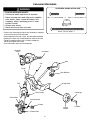
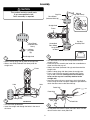
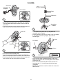
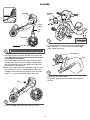
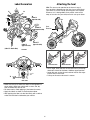
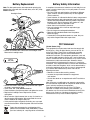
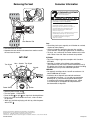
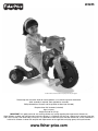
W4695
Product features and decorations may vary from the photograph.
Please keep this instruction sheet for future reference, as it contains important information.
Adult assembly is required. Tools required for assembly:
Phillips Screwdriver, Hammer and Scrap Block of Wood (not included).
Requires three "AA" batteries (included).
Age: 2-6 years.
Weight limit: 60 lbs (27 kg).
IMPORTANT! It is good practice to start training children very young regarding the importance of helmet use.
When children are older and riding bicycles and faster vehicles, it is important that they use a helmet each and every time they
ride. For this reason, even while riding a tricycle, it is a good idea to familiarize your child with helmet use, so that it becomes a
habit for life. Choose a helmet that complies with requirements of the applicable certifying agency for bicycle helmets.
www.fisher-price.com
Consumer Information
WARNING
FASTENERS SHOWN ACTUAL SIZE
TO AVOID SERIOUS INJURY:
• Continuous adult supervision is required.
• Never use near cars and other motor vehicles,
near streets, steps, sloped driveways, hills,
roadways, alleys, swimming pools or other
bodies of water.
• Always wear shoes.
• Never allow more than one rider.
#8 x 3/ 4" (1,9 cm) Screw – 4
Cap Nut – 1
#8 x 3" (7,6 cm) Screw – 1
• Please save all packaging material until assembly is complete
to ensure that no parts are discarded.
• Please wipe each part with a clean, dry cloth before assembly.
• Some parts shown are assembled to both sides of the trike.
• Tighten assembled screws with a Phillips screwdriver.
Do not over-tighten the screws.
• Parts not shown: labels and assembly tool.
Headlight
Cover
#6 x ½" (1,3 cm) Screw – 3
Handlebar
Seat
Cap
Frame
Seat Retainer
Straight Axle
Fork
2 Fork Covers
2 Hubcaps
Front Wheel
Axle Assembly
Pedal
2 Rear
Wheels
4 Pedal Hubs
2
2 Covers
Assembly
CAUTION
This product contains small parts
in an unassembled state.
Adult assembly is required.
Hubcap
(Peg Side Down)
Cap Nut
Rear Wheel
(Indented Side Up)
Cover
Straight Axle
Frame
Rear Wheel
(Indented Side
Down)
Scrap Block
of Wood
3
Straight Axle
• Turn the frame on its side with the exposed end of the
straight axle up.
• Place the cap nut assembly tool under the assembled rear
wheel and onto the cap nut.
• Slide a rear wheel (indented side up) onto the end of the
straight axle.
• Slide a hubcap (peg side down) onto the straight axle.
• Place a cap nut on the end of the straight axle. Tap the
cap nut with a hammer. Gently pull the rear wheel up
to be sure the cap nut is securely attached to the
straight axle.
• Insert one of the tabs on a cover into a slot in the hubcap.
Push to snap the cover into place. Repeat this procedure to
attach the other cover to the other hubcap.
• Slide a hubcap (peg side up) onto the straight axle.
• Slide a rear wheel (indented side down) onto the
straight axle.
Frame
Hole
Cap Nut
Assembly Tool
Assembled
Rear Wheel
Hubcap
(Peg Side
Up)
1
Hubcap
Hole
Pedal Hub
Pedal Axle
2
Tabs
Straight Axle
Slot
BOTTOM VIEW
Pedal Hub
4
• Turn the frame upside down.
• Insert the straight axle through the holes in the rear of
the frame.
• Fit two pedal hubs onto the pedal axle tabs. Make sure the
tabs fit into the slot in each pedal hub.
3
Assembly
Pedal Hubs
Pedal Axle
Assembly
Front Wheel
Pedal
Pedal Axle
5
• While holding the pedal hubs on the pedal axle assembly,
insert the pedal axle through the hole in the center of the
front wheel.
• Push the pedal hubs into the center of the front wheel until
they are flush with the surface of the front wheel.
Scrap Block
of Wood
7
• Fit the pedal on the pedal axle. Tap the pedal with
a hammer until it is secure.
• Pull the pedal up to be sure it is secure. If you can remove
it, you have not secured it properly. Tap it with the
hammer again.
Pedal Hub
Fork Arms
Fork Cover
Pedal Hub
Groove
6
• Turn the front wheel assembly over.
• Insert the remaining pedal hubs on top of and below the
pedal axle and into the hole in the center of the front wheel.
• Push the pedal hubs into the center of the front wheel until
they are flush with the surface of the front wheel.
8
Pedal Axle
• Place the front wheel assembly between the fork arms.
Make sure the pedal axle fits into the groove at the bottom
of each fork arm.
• Place a fork cover over the pedal axle on one fork arm.
• Insert two #8 x 3/ 4" (1,9 cm) screws into the fork cover
and tighten.
• Repeat this procedure to attach the other fork cover to the
other fork arm.
4
Assembly
Handlebar
Headlight
Cover
Frame
Neck
Fork
Post
Fork Cover
11
• Fit the the headlight cover onto the front of the handlebar.
• Insert three #6 x 1/2" (1,3 cm) screws into the headlight
cover. Tighten the screws.
Rear of Trike
9
Seat Retainer
• Insert the fork post up through the hole in the neck of the
frame. Make sure the fork is positioned so that the fork
covers face the rear wheels.
• Place the handlebar onto the fork post and push it down
onto the frame. Make sure the handlebar is positioned so
that the screw hole faces the rear wheels and aligns with
the screw hole in the fork post.
Hint: You may need to rotate the handlebar to align the holes.
• Insert the #8 x 3" (7,6 cm) screw through the hole in the
handlebar and into the fork post so that part of the screw
(about 3/4" - 1,9 cm) is still visible. Tighten the screw.
Seat
Peg
12
• Position the seat upside down.
• Fit the small pegs on the seat retainer into the holes in
the seat.
Cap
10
• Insert and “snap” the cap into the hole in the frame.
5
Label Decoration
Attaching the Seat
Hint: The seat can be attached to the frame in any of
three positions, depending on the size of your child. Check
your child’s fi t on the trike by observing the seat to pedal
distance, as it is being ridden. If the pedals seem too far
away or too close for your child, move the seat up or down.
7
13
14
2
ra
Do
m
.
2.
co
05 l, Inc
Via
. 14 tte
of
rks
N.Y Ma d.
of
a,
rve ma
ror rks se de
0
31 Inc., st Au ma Re tra
de hts are
5-0 e,
69 ric ., Ea . tra Rig rs
cte
W4 r-P Inc U.S All
l,
.
he
tte are Inc chara
Fis
d
Ma ls al
1
ee on , an
01 Wh ati
©2 r ern logos
we Int
of
s,
ry
Po
d com title
idia
bs e an Via ated
su ric 1
rel
r-P 01
he ©2 d all
an
rer
plo
Ex
Fis
e
Th
A
Tabs
Int
3
n,
eo
lod
ke
6
10
(Label 8
opposite side)
al
on
ati
ern
.
Inc
11
(Label 12
opposite side)
1
1
(Label 1's both sides)
4
(Label 5
opposite side)
Seat
Retainer
16
(Label 17
opposite side)
Slots
SIDE VIEW
Lower Position
Middle Position
Upper Position
• At an angle, insert the tabs on the seat into any of the top
three sets of slots for the lower, middle or upper position.
• Lower the seat so that the seat retainer inserts and snaps
into the slots in the frame.
• Pull up on the seat to be sure it is secure.
9
15
DASH VIEW
• Make sure the areas where the labels will be applied are
clean and dry. Wipe your vehicle with a clean, soft, dry
cloth to remove any dust or oils.
• For best results, avoid applying a label more than once.
• Apply the labels as shown in the illustration above.
• After applying the label, rub the label firmly with a cloth to
make sure the label is adhered to your vehicle.
6
Battery Replacement
Battery Safety Information
Note: For best performance, we recommend replacing the
batteries that came with this trike with three, new "AA" (LR6)
alkaline batteries.
In exceptional circumstances, batteries may leak fluids that can
cause a chemical burn injury or ruin your product. To avoid
battery leakage:
• Do not mix old and new batteries or batteries of different
types: alkaline, standard (carbon-zinc) or rechargeable
(nickel-cadmium).
• Insert batteries as indicated inside the battery compartment.
• Remove batteries during long periods of non-use. Always
remove exhausted batteries from the product. Dispose of
batteries safely. Do not dispose of this product in a fire.
The batteries inside may explode or leak.
• Never short-circuit the battery terminals.
• Use only batteries of the same or equivalent type,
as recommended.
• Do not charge non-rechargeable batteries.
• Remove rechargeable batteries from the product
before charging.
• If removable, rechargeable batteries are used, they are
only to be charged under adult supervision.
Headlight Cover
FCC Statement
1
(United States Only)
This equipment has been tested and found to comply with
the limits for a Class B digital device, pursuant to Part 15
of the FCC Rules. These limits are designed to provide
reasonable protection against harmful interference in a
residential installation. This equipment generates, uses and
can radiate radio frequency energy and, if not installed and
used in accordance with the instructions, may cause harmful
interference to radio communications. However, there is
no guarantee that interference will not occur in a particular
installation. If this equipment does cause harmful interference
to radio or television reception, which can be determined by
turning the equipment off and on, the user is encouraged to
try to correct the interference by one or more of the
following measures:
• Reorient or relocate the receiving antenna.
• Increase the separation between the equipment
and receiver.
• Consult the dealer or an experienced radio/TV technician
for help.
Note: Changes or modifications not expressly approved by
the manufacturer responsible for compliance could void the
user’s authority to operate the equipment.
This device complies with Part 15 of the FCC Rules.
Operation is subject to the following two conditions: (1)
this device may not cause harmful interference and (2) this
device must accept any interference received, including
interference that may cause undesired operation.
• Loosen and remove the screws from the headlight cover.
Remove the headlight cover.
1,5V x 3
“AA” (LR6)
2
• Loosen the screw in the battery compartment door. Open
the battery compartment door.
• Insert three "AA" (LR6) alkaline batteries.
• Close the battery compartment door and tighten the screw.
• Replace the headlight cover. Replace the screws
and tighten.
• When sound or lights become faint or stop, it's time for an
adult to replace the batteries. We recommend the use of
alkaline batteries for longer battery life.
• If this product begins to operate erratically, you may need
to reset the electronics. Slide the power switch off and then
back on.
• Protect the environment by not disposing of this
product with household waste (2002/96/EC). Check
your local authority for recycling advice and facilities.
7
Removing the Seat
Consumer Information
Seat
CONSUMER ASSISTANCE
1-800-432-5437 (US & Canada)
1300 135 312 (Australia)
Fisher-Price, Inc., 636 Girard Avenue, East Aurora, NY 14052.
Hearing-impaired consumers: 1-800-382-7470.
Seat Retainer Tab
Outside the United States:
Canada: Mattel Canada Inc., 6155 Freemont Blvd.,
Mississauga, Ontario L5R 3W2; www.service.mattel.com.
Great Britain: Mattel UK Ltd, Vanwall Business Park,
Maidenhead SL6 4UB. Helpline: 01628 500303.
www.service.mattel.com/uk
Mattel Europa, B.V., Gondel 1, 1186 MJ Amstelveen, Nederland.
Australia: Mattel Australia Pty. Ltd., 658 Church Street,
Locked Bag #870, Richmond, Victoria 3121 Australia.
New Zealand: 16-18 William Pickering Drive,
Albany 1331, Auckland.
Seat Retainer Tab
• Turn the frame on its side.
• Squeeze the seat retainer tabs toward one another and lift
the seat from the frame.
Let's Go!
Turn Signal
Horn Sounds Turn Signal
Sounds
Power Switch
Care
• Check the plastic parts regularly and if broken or cracked,
dispose of them properly.
• Check all fasteners regularly to be sure they are tight.
If the fasteners are not tight, tighten them as necessary.
• To clean, use a mild soap and water solution and a clean
cloth. Rinse clean with water to remove soap residue.
ICES-003
• This Class B digital apparatus complies with Canadian
ICES-003.
• Operation is subject to the following two conditions:
(1) this device may not cause harmful interference and (2)
this device must accept any interference received, including
interference that may cause undesired operation.
NMB-003
• Cet appareil numérique de la classe B est conforme à la
norme NMB-003 du Canada.
• L’utilisation de ce dispositif est autorisée seulement
aux conditions suivantes : (1) il ne doit pas produire de
brouillage et (2) l’utilisateur du dispositif doit être prêt
à accepter tout brouillage radioélectrique reçu, même
si ce brouillage est susceptible de compromettre le
fonctionnement du dispositif.
Ignition
•
•
•
•
Slide the power switch ON .
Turn the ignition, “VRROOOM!”
Press the left
or right
turn signals for flashing blinkers.
Press any of the sound buttons for music, a horn or other
fun phrases!
• When you are finished playing with this toy, slide the power
switch OFF .
©2011 Viacom International Inc. All Rights Reserved. Nickelodeon, Dora the Explorer
and all related titles, logos and characters are trademarks of Viacom International, Inc.
Fisher-Price, Inc., a subsidiary of Mattel, Inc., East Aurora, NY 14052 U.S.A.
©2011 Mattel, Inc. All Rights Reserved. ® and ™ designate U.S. trademarks of Mattel, Inc., unless otherwise indicated.
PRINTED IN MEXICO
W4695pr-0920