1
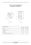
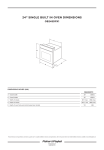
Installation instructions
Aerotech oven
NZ AU
OB76 models
Important!
SAVE THESE INSTRUCTIONS
The models shown in this document may not be available in all markets and are subject to change at any time. For current details about model and specification availability in your country, please go to our website
www.fisherpaykel.com or contact your local Fisher & Paykel dealer.
1 SAFETY AND WARNINGS
WARNING!
Always disconnect the oven from
the mains electricity supply
before carrying out any
maintenance operations or
repairs.
Failure to do so may result in
electrical shock or death.
SINGLE
OVEN
MODELS
Electrical hazard
DOUBLE
OVEN
MODELS
WARNING!
Very Heavy
409 lb
186 kg
Do not attempt to lift this
product unassisted.
Lifting unassisted may
cause serious injury.
242 lb
110 kg
WARNING!
Cut hazard
Take care - panel edges are sharp.
Failure to use caution could result in injury or cuts.
Important safety precautions!
To avoid hazard, follow these instructions carefully before installing or using this product.
Please make this information available to the person installing the product as it could reduce your
installation costs.
This oven is to be installed and connected to the electricity supply only by an authorised person.
If the installation requires alterations to the domestic electrical system, call a qualified electrician. The
electrician should also check that the socket cable section is suitable for the electricity drawn by the oven.
The oven must be earthed.
To connect the oven to the mains, do not use adapters, reducers or branching devices as they can cause
overheating and burning.
Installation must comply with your local building and electricity regulations.
Failure to install the oven correctly could invalidate any warranty or liability claims.
Before you install the oven, please make sure that
The oven will rest on a flat surface that can support its weight.
The benchtop and oven cavity are square and level, and are the required dimensions.
The height from the floor suits the user.
The oven door can open fully without obstruction.
a suitable disconnection switch is incorporated in the permanent wiring, mounted and positioned to
comply with the local wiring rules and regulations. A means of disconnection with at least a 3 mm air gap
contact separation in all poles must be incorporated into the fixed wiring in accordance with the wiring
rules, unless the local wiring rules allow for the following variation:
A means of disconnection from the supply having and air gap separation in all active (phase) conductors
must be incorporated into the fixed wiring.
the electrician provides sufficient free length of power supply cable to reach from the bottom rear of the
cavity to at least 1.5 metres in front of the bottom edge of the opening. The cable may enter the cavity
from the side, top or bottom, but top entry must be at the rear of the cavity.
When you install the oven
Do not seal the oven into the cabinetry with silicone or glue. This makes future servicing difficult. Fisher &
Paykel will not cover the costs of removing the oven, or of damage caused by this removal.
Use the supplied screws and spacers to secure the oven to the cabinetry. Do not over-tighten the screws.
Do not stand on the door, or place heavy objects on it.
Do not lift the oven by the door handle.
Take extra care not to damage the lower trim of the oven.
Use easy-to-clean finishes for the wall surfaces surrounding the oven, so that cooking fume staining
resulting from using the oven is easy to remove.
2 PRODUCT AND CABINETRY DIMENSIONS
3 PRODUCT AND CABINETRY DIMENSIONS
Single oven models
Double oven models
II
I
II
I
C
E
B
C
E
K
B
J JI
J JI
K
A
D
A
D
H
Proud install
F
16-20 mm
G
Flush install
Proud install
16-20 mm
16-20 mm
H
G
Flush install
16-20 mm
F
G
G
2.5 mm
Installation diagrams for illustration purposes only
overall height of product
688
overall width of product
757
overall depth of product (without handle)
608
height of chassis
675
width of chassis
718
depth of chassis
570
depth of oven frame and control panel (excl. knobs)
38
depth of oven door (open) (measured from front of oven frame)
530
minimum inside width of cavity
724
overall width of cabinetry
762
inside height of cavity
681
overall height of cabinetry
693
minimum inside depth of cavity
575
Note: If installing a cooktop above the oven, ensure adequate clearance is provided for the cooktop as per the
cooktop manufacturer’s instructions.
2.5 mm
Ensure the cavity is completely sealed with no gaps
Product and cabinetry dimensions (mm)
A
B
C
D
E
F
G
H
I
II
J
JI
K
OB76 D
models
A
B
C
D
E
F
G
H
I
II
J
JI
K
2.5 mm
Ensure the cavity is completely sealed with no gaps
OB76 S
models
Product and cabinetry dimensions (mm)
2.5 mm
overall height of product
1230
overall width of product
757
overall depth of product (without handle)
608
height of chassis
1217
width of chassis
718
depth of chassis
570
depth of oven frame and control panel (excl. knobs)
38
depth of oven doors (open) (measured from front of oven frame)
530
minimum inside width of cavity
724
overall width of cabinetry
762
inside height of cavity
1222
overall height of cabinetry
1235
minimum inside depth of cavity
575
4 CABINETRY PREPARATION
5 ELECTRICAL CONNECTION
Double models featured for illustration purposes only
Proud install
16-20 mm
575 mm
Flush install
38 mm
OB76 Single
Max. current draw:
Max. load:
19.4 A
4.6 kW
OB76 Double
Max. current draw:
Max. load:
38.3 A
9.2 kW
Nameplate
575 mm
We recommend that the outlet for the power supply cable is located in the
right rear corner of the cabinet cavity. This allows the power supply cable
to sit inside the rear chamfered corner of the oven and prevents it being
jammed between the cabinet wall and the rear of the oven.
613 mm
Important!
Ensure you have
created a 38 mm recess
in cabinetry if flush
installing.
6 UNPACK THE OVEN AND REMOVE THE DOOR(S)
A
B
1
3
4
1
Important!
Ensure you remove
the long trim from
the packaging
2
4
7 SECURE THE OVEN TO THE CABINETRY AND REFIT THE DOOR(S)
A
Ensure supplied spacer
is fitted between oven
and cabinetry
B
1
1
1
2
1
3
1
2
4
Take care not to
damage the lower trim
of the oven
2
8 FLUSH INSTALLATION ONLY - REPLACE THE LOWER TRIM WITH THE SUPPLIED LONG TRIM
A
Unscrew and remove the
installed lower trim
B
1
1
Replace with the
supplied long trim
Ensure the clips
on the long trim
locate into the
channels
2
Please turn over >
9 FINAL CHECKLIST
Make sure the appliance is level and securely fitted to the cabinetry and both
oven doors open and close freely.
Make sure all the internal packaging has been removed from the oven cavity.
Make sure all oven vents and openings are clear and are free of any
obstruction/damage.
Important!
Failure to make sure all oven vents are unobstructed may result in poor product performance.
Turn the power to the oven on. The clock should light up and flash 12:00pm.
Set the clock to the current time.
TO
1) Rotate the PUSH
button until the correct time is showing.
CLEAR
2) Press the CLOCK button to set the time, or wait eight seconds and it will set
automatically.
Turn the oven function knob to ‘Bake’ and the oven temperature knob to
180 oC. Air should blow out of the vent at the bottom of the oven. Inside the
oven cavity, all three oven lights should come on. After five minutes, open the
oven door and the air inside should feel warm and the top element should be
glowing red.
Turn both the oven function knob and oven temperature knob back to OFF
and repeat for the other oven if the appliance is a double model.
10 TROUBLESHOOTING
If the appliance is not functioning correctly after installation, check the
following:
Check that the circuit breaker has not tripped or the fuse blown.
Make sure that the electrical connections have been correctly made.
Make sure that power is being supplied to the oven.
Make sure the voltage is correct across all phases.
If a problem occurs, consult the Troubleshooting section of the User Guide.
If after checking these points you still need assistance, please refer to the
Service & Warranty book for warranty details and your nearest Authorised
Service Centre, or contact us through our website, www.fisherpaykel.com.
599510A NZ AU 03.08