1
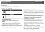
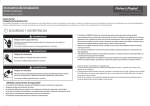
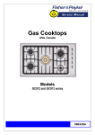
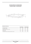
(1,1) -1- 599489D izona vsisland install A2 NZGB.indd 21/7/09 2:51:59 PM
Installation instructions
IZONA VentSurface
HI120 ISLAND models
NZ AU GB IE
Important!
SAVE THESE INSTRUCTIONS
The models shown in this document may not be available in all markets and are subject to change at any time. For current details about model and specification availability in your country, please go to our local
website listed at the end of this document or contact your local Fisher & Paykel dealer.
1 SAFETY AND WARNINGS
WARNING!
Electrical shock hazard
Always disconnect the appliance from the mains electricity supply before
carrying out any servicing or maintenance operations.
Failure to do so could result in electrical shock or death.
WARNING!
Cut Hazard
Take care - panel edges are sharp.
Failure to use caution could result in injury or cuts.
Important safety instructions!
To avoid hazard, read and follow these instructions carefully before installing or
using this appliance.
Please make this information available to the person installing the appliance, as it
could reduce your installation costs.
This appliance is to be installed and connected to the electricity supply only by a
qualified electrician.
Installation must comply with your local building and electricity regulations.
Failure to install the appliance correctly could invalidate any warranty or liability
claims.
This appliance is designed for permanent fixture and has to be connected to the
mains electricity supply.
The appliance must not be installed above cookers with eye-level grills.
The appliance is heavy, take care when lifting or handling.
Before you install the appliance, please make sure that
the voltage (V) and frequency (Hz) indicated on the serial number plate as well as
the specifications on the rating plate on the inside of the appliance correspond to
the voltage and frequency of the mains supply.
the room in which the appliance is installed is well-ventilated.
the ceiling is able to withstand the total weight (56 kg) of the appliance suspended from it.
if the air is to be ducted, the flue is in good condition, especially if it has been out of
use for a long period of time.
If the air is to be ducted, it will not be discharged into a flue that is used for
exhausting fumes from appliances burning gas or other fuels.
the installation will comply with laws and regulations regarding ducting waste
gases.
for optimal efficiency, use smooth ducting for reduced noise and increased airflow. Flexible ducting
should only be used as a last resort.
When you install the appliance, please make sure that
a suitable isolating switch is incorporated in the permanent wiring, mounted
and positioned to comply with the local wiring rules and regulations. The switch
must be of an approved type installed in the fixed wiring and have a contact separation in all poles
that provide full disconnection under overvoltage category III conditions.
it is not installed and connected to flues where other appliances are installed
and which run off energy supplies other than electricity (eg water heaters, boilers,
gas cookers).
the power supply cable (type H05VV-F 3x0.75 mm2) is connected to terminals marked with
the letters L (power line) and N (neutral) mounted on the appliance and is secured
in position by a cable gland.
the power supply cable is connected to a suitable and easily accessible fixed power outlet or
isolating switch.
the power outlet or isolating switch remains accessible after installation and the appliance can be
disconnected from the electricity supply.
exhaust air is not discharged into a heating flue or wall cavity, unless the cavity is designed for that
purpose.
If you install using the external ducting through a side wall, ensure the surface area of the external
venting grill is no smaller than 150 cm2.
the glass and stainless steel components are handled with care. These are easily damaged if abraded
or knocked by tools.
(1,2) -1- 599489D izona vsisland install A2 NZGB.indd 21/7/09 2:51:59 PM
2 PRODUCT DIMENSIONS
3 CLEARANCE DIMENSIONS
Installation diagrams for illustration purposes only
F
C
A
E
A
F
A
G
GAS
D
B
ELECTRIC
C
Product dimensions (mm)
HI120
A
B
C
D
E
F
G
H
overall height of product (adjustable)
939
overall width of product
1198
overall depth of product
648
height to fixed flue section
62
width of flue
266
depth of flue
277
height from top of glass surface to top of fixed flue section
length of power supply cable
334
1450
A
minimum clearance from bottom of VentSurface to:
trivets or pot support surface of gas cooktops
pot support surface of electric cooktops (including induction)
*Note: to ensure that the VentSurface is able to perform at its best , we recommend that the
clearance between the VentSurface and the cooking surface does not exceed 800 mm.
HI120
Clearances (mm)
750
650
(2,1) -1- 599489D izona vsisland install A2 NZGB.indd 21/7/09 2:51:59 PM
4 PARTS SUPPLIED
Extendable
flue cover (1)
Vertical flue
mounting support
brackets (4)
Support frame
for vertical flue
mounting support
brackets (1)
4 x 16
Washers (4)
3.5 x 9.5
Screws (46)
4 x 50 Screws (4)
and corresponding
wall anchors (4)
Upper glass (1)
Aluminium
mesh filter (1)
Plastic vent
duct (1)
Ceiling
mounting
frame (1)
Note: ducting accessories, carbon filter and the Ductless Recirculating Kit are NOT supplied with your VentSurface but need to be purchased separately. They are available from your nearest Fisher & Paykel Authorised
Service Agent, or www.fisherpaykel.com.
5 VENTILATION OPTIONS
6 RATING PLATE LOCATION
TYPE
Cod.
SERIE
BATCH
V
External ducting
Recirculation
(Requires Carbon Filter, to
be purchased separately
as part of the Ductless
Recirculating Kit. Contact
your nearest Fisher & Paykel
Authorised Service Agent or
www.fisherpaykel.com for
instructions and details.)
Hz
W tot
W MAX
W
L
1 2 3
L
M2
External ducting
through a side wall
or ceiling
Recirculation
recirculates filtered air
back into the kitchen
M1
(2,2) -1- 599489D izona vsisland install A2 NZGB.indd 21/7/09 2:51:59 PM
7 SECURE MOUNTING FRAME TO CEILING & MOUNT UPPER GLASS
A
B
1
6 mm holes
x4
2
Ensure the washers
provided are used
8 ATTACH PLASTIC VENT DUCT & ASSEMBLE VERTICAL MOUNTING BRACKETS
A
B
1
1
x4
2
(1,1) -2- 599489D izona vsisland install A2 NZGB.indd 21/7/09 2:52:11 PM
9 ATTACH VERTICAL MOUNTING BRACKETS & SLIDE ON FLUE COVER
A
B
1
2
1
2
x 16
10 ATTACH MOUNTING BRACKETS TO MOUNTING FRAME & ATTACH FLUE COVER
A
B
2
x8
2
1
1
Important!
VERY HEAVY: Ensure that the
ceiling is able to withstand
the total weight (56 kg) of the
appliance suspended from it.
x4
(2,1) -2- 599489D izona vsisland install A2 NZGB.indd 21/7/09 2:52:11 PM
11 OPTIMISING THE VENTSURFACE BY SELECTING COOKTOP TYPE
To ensure best performance, the type of cooktop under the VentSurface needs to be selected after installing the appliance.
To select the type of cooktop
1
2
3
Make sure the VentSurface is on stand-by (plugged into a power outlet which is switched on but the fan is off ).
Press the
and
buttons simultaneously. A single horizontal segment will appear in the display.
Release and re-press the buttons simultaneously again to scroll through the types of cooktops:
Top segment – Gas
Middle segment – Induction
Bottom segment – Electric/Ceramic
Gas
4
To store the type of cooktop last selected, press the
Induction
or
Electric
Ceramic
button.
12 SELECTING FILTER MODE
After installation, the VentSurface has to be set to operate on aluminium mesh filter mode (if the extracted air is ducted outside) or carbon filter mode (if the extracted air is recirculated indoors).
To change between filter modes
1 Make sure the VentSurface is on stand-by (plugged into a power outlet which is switched on but the fan is off ).
2 Press the
button.
3a The display will show the “-“ symbol, indicating that the VentSurface is set to aluminium mesh filter mode (external ducting).
OR
3b The display will show the “C” symbol, indicating that the VentSurface is set to carbon filter mode (internal recirculation).
4
Press the
button and hold down for at least five seconds to change to the filter mode you want. The filter mode last selected will be activated.
(2,2) -2- 599489D izona vsisland install A2 NZGB.indd 21/7/09 2:52:11 PM
13 FINAL CHECKLIST
TO BE COMPLETED BY THE INSTALLER
Have you used the correct fixing screws?
Have you used the wall anchors provided?
Have you used the washers provided?
Have you made sure that all standard requirements for ducting/
recirculation and electrical connection are met?
Is the VentSurface set for the correct cooktop type and filter mode?
Is there a means of disconnection from the mains electricity
supply (disconnection switch or power outlet) accessible to the customer
after installation?
Have you removed the protective blue film from the stainless steel surfaces?
Is the VentSurface earthed?
OPERATION:
Have you informed the customer about the cleaning alerts?
Have you demonstrated the basic operation to the customer?
Installer’s name:
Installer’s signature:
Installation company:
Date of installation:
LEAVE THESE INSTRUCTIONS WITH THE CUSTOMER
www.fisherpaykel.co.nz www.fisherpaykel.com.au www.fisherpaykel.co.uk www.fisherpaykel.ie 599489D NZ AU GB IE 07.09