1
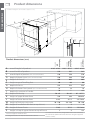
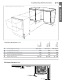
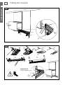
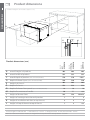
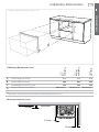
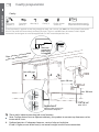
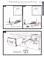
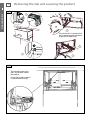
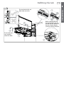
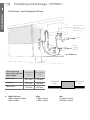
Installation instructions
DD605 and DS605 models
DishDrawer
NZ AU GB IE
Safety and warnings
WARNING!
Electrical hazard
Before installing the DishDrawer® , remove the house fuse or open the circuit
breaker.
If permanently connecting the DishDrawer®, be sure the power is isolated
and the DishDrawer® unplugged.
This appliance must be grounded. In the event of a malfunction or
breakdown, grounding will reduce the risk of electric shock by providing
a path of least resistance for electric current. This appliance is equipped
with a cord having an equipment-grounding conductor and a grounding
plug. The plug must be plugged into an appropriate outlet that is installed
and grounded in accordance with all local codes and ordinances. Improper
connection of the equipment-grounding conductor can result in a risk of
electric shock. Check with a qualified electrician or service representative if
you are in doubt as to whether the appliance is properly grounded.
Do not modify the power supply plug provided with the appliance - if it will
not fit the outlet, have a proper outlet installed by a qualified electrician. Do
not use an extension cord, adapter plug or multiple outlet box.
Failure to do so may result in electrical shock or death
WARNING!
Cut Hazard
Take care - panel edges are sharp.
Failure to use caution could result in injury or cuts.
Important safety precautions!
Installation of this DishDrawer® requires basic mechanical and electrical skills.
Be sure to leave these Instructions with the Customer.
Installation must comply with your local building and electricity regulations.
At the completion of the DishDrawer® installation, the Installer must perform Final Check List.
Remove all packaging materials supplied with the DishDrawer®.
This dishwasher is manufactured for indoor use only.
Ensure all water connections are turned OFF. It is the responsibility of the plumber and
electrician to ensure that each installation complies with all Codes and Regulations.
The DishDrawer® MUST be installed to allow for future removal from the enclosure if service is
required.
The switched power outlet must be outside the DishDrawer® cavity so that it is accessible after
installation.
Care should be taken when the appliance is installed or removed to reduce the likelihood of
damage to the power supply cord.
If the DishDrawer® is to be relocated from one installation to another it must be kept upright to
avoid damage from water spillage.
Make sure only new hoses are used for connection (supplied with DishDrawer®). Old hoses
should not be reused.
Failure to install the DishDrawer correctly could invalidate any warranty or liability claims.
1
Contents
DOUBLE MODELS
Product and cabinetry dimensions
Installation
Cavity preparation
Route the hoses and move into the cavity
Removing the tub and levelling the product
Securing the product and refitting the tub
Plumbing and drainage - OPTION 1
Plumbing and drainage - OPTION 1 (connection)
Plumbing and drainage - OPTION 2
Plumbing and drainage - OPTION 2 (connection)
Fitting the toekick
SINGLE MODELS
Product and cabinetry dimensions
Installation
Cavity preparation
Route the hoses and move into the cavity
Removing the tub and securing the product
Refitting the tub
Plumbing and drainage - OPTION 1
Plumbing and drainage - OPTION 1 (connection)
Plumbing and drainage - OPTION 2
Plumbing and drainage - OPTION 2 (connection)
Final checklist
Important!
SAVE THESE INSTRUCTIONS
The models shown in this User Guide may not be available in all markets and are
subject to change at any time. For current details about model and specification
availability in your country, please go to our website www.fisherpaykel.com or
contact your local Fisher & Paykel dealer.
2
4
5
6
7
8
9
10
11
12
14
16
17
18
19
20
21
22
23
24
2
Product dimensions
DOUBLE MODELS
Installation diagrams for illustration purposes only
C
B
N
D
P
I
G
K
H
E
C
L
A
O
G
I
N
F
M
J
DD605
Integrated
DD605
overall height* of product
Prefinished
Flat door
DD605
A
B
C
D
E
F
G
H
I
J
K
L
M
N
O
P
Prefinished
LCD
Product dimensions (mm)
819.5 - 879.5
819.5 - 879.5
819.5 - 879.5
overall width of product
595
595
595
overall depth of product (excl. curvature/handle)
570
570
570
depth of drawer (open) (excl. curvature/handle)
520
520
520
height* of chassis
809
809
809
60
60
60
552
552
552
18
18
18
height range of levelling feet
depth of chassis
depth of drawer front panel (excl. curvature/handle)
depth of curvature or handle
depth of kickstrip
height of upper drawer front
height of lower drawer front
height of kickstrip (adjustable)
height of installation tab slots (on top of chassis)
height of drawer fronts
height* of top of upper drawer to top of chassis
* Chassis heights include tab slots
** Designer handle - 41 mm, Curved handle - 36 mm
30
**
n/a
50 - 65
50 - 65
67 - 127***
394
398
398 min
312.5
311.5
311.5 min
70 - 120
70 - 120
70 - 120
2
2
2
719.5
717.5
717.5 min
7
2
n/a
*** Prefinished 50-65 mm; Integrated 67 mm less the Kickstrip
Panel thickness (Minimum Panel thickness using the supplied
screws is 9 mm).
Cabinetry dimensions
3
Installation diagrams for illustration purposes only
D
DOUBLE MODELS
B
A
C
E
DD605
Integrated
DD605
inside height of cavity
Prefinished
Flat door
DD605
A
B
C
D
E
Prefinished
LCD
Cabinetry dimensions (mm)
820 - 882.5
820 - 882.5
820 - 882.5
inside width of cavity
600
600
600
inside depth of cavity (inside)
580
580
580
height of adjacent cabinetry
720
720
720
70 - 120
70 - 120
70 - 120
height of kickstrip
Minimum clearances (mm)
2.5 mm
2.5 mm
13 mm
DOUBLE MODELS
4
Cavity preparation
Parts supplied
Drain hose
support (1)
Drain hose Wire clip (2) Clamp (1)
joiner (1)
Phillips
Moisture
Prefinished toe kick (1)
16 mm
protection
White or Black
screws (9) tape (1)
Hexagonal sockets (2)
(to prevent moisture
(Long & Short)
damage)
If the Drain hose(s) supplied are not long enough to reach your services, you must use a Drain Hose Extension Kit
P/N 525798 which will extend the drain hose(s) by 3.6m. The kit is available from the nearest Fisher & Paykel
Authorized Service Agent or www.fisherpaykel.com. DO NOT extend beyond this limit.
Install
tabs (2)
90o
Moisture
10 mm protection
tape must
be applied.
d
te
a
c
lo
an be
c
s
e
ic
v
r
.
Note: Se
Drawer®
e of Dish
id
s
r
e
h
it
e
max. 450 mm
min. ø50 mm
min. 200 mm
*
*
220-240 VAC
min. 9 A
These marks indicate mounting tab screw locations
*
Preferred position. If adequate clearance, services hole can be higher to clear toe kick space.
If hole is higher, ensure drain hose(s) are routed straight into the waste connection.
Route the hoses and move into the cavity
1b
DOUBLE MODELS
1a
5
2
1
Tie together to avoid kinking
2
2
If top two tabs are being
used, ensure they’re securely
fitted before sliding product
into cavity.
optional
optional
3
3
Loosen feet first, but
do not fully extend
until product is in cavity.
1
1
Ensure hoses and cord
are not kinked or twisted.
Removing the tub and levelling the product
6
3
4
DOUBLE MODELS
1
Ensure the tub is removed and
then rotated counter-clockwise
to prevent kinked hoses.
2
5
30 mm
3
5
4
Ensure product is level. Using the most appropriate length
Hexagonal socket supplied, and a screwdriver, fully extend
levelling feet up to required distance.
Hexagonal socket
1
2
4
5
x4
3
Securing the product and refitting the tub
7
DOUBLE MODELS
5
The mounting tabs
are in pairs, one on
each side of the
product. At least two
sets of tab pairs must
be used.
A and B tab pairs
OR B and C tab pairs
or all three pairs.
C
C
optional
Ensure the sound
insulation is
repositioned
correctly.
B
B
A
A
6
3
Ensure the tub clips on
both sides are reset.
5
4
Before refitting the tub,
ensure the hoses are not
twisted and the latches at
the rear of each drawer
runner are facing forward.
4
Ensure the tub is
now rotated
clockwise back.
1
2
8
Plumbing and drainage - OPTION 1
DOUBLE MODELS
DishDrawer® and Standpipe Ø38 mm
Waste disposal
(optional)
Do not connect to
DishDrawer®
750 - 882.5 mm
Waste
Waste
Valve
Water
supply
(COLD)
min. R200 mm
Max. distance of
hoses and cord from
chassis edge
Left hand
side
Right hand
side
Drain hose
2011 mm
1794 mm
Inlet hose
1561 mm
1344 mm
Power cord
1776 mm
1559 mm
Water Pressure
Water softener models
Other models
Max
1 MPa (145 psi)
1 MPa (145 psi)
Left hand
side
Right hand
side
Min
0.1 MPa (14.5 psi)
0.03 MPa (4.3 psi)
Drains will need to be separated to satisfy Kosher requirements. We suggest you confirm
acceptability with your local Rabbi in respect to Kosher installations.
Plumbing and drainage - OPTION 1 (connection)
9
7
DOUBLE MODELS
DishDrawer® and Standpipe Ø38 mm
If space is limited
for fixing, push hose
through drain hose
support to required
height
1
750882.5
mm
max.
120
mm
38 mm
2
8
1
Fit supplied
washer
180o
2
3
4
Plumbing and drainage - OPTION 2
DishDrawer® using sink trap with drain hose joiner
Supplied drain
hose joiner
HIGHLOOP
min. 150 mm
750 - 882.5 mm
DOUBLE MODELS
10
Waste
Valve
Water
supply
(COLD)
min. R200 mm
Plumbing and drainage - OPTION 2 (connection)
11
7
DOUBLE MODELS
DishDrawer® using sink trap with drain hose joiner
If space is limited
for fixing, push hose
through drain hose
support to required
height
1
750882.5
mm
2
3
8
1
Ensure hoses are routed
straight to joiner. Remove
excess hose material if
necessary.
Fit supplied
washer
180o
2
3
4
Fitting the toekick
12
DOUBLE MODELS
9
1
2
3
10
4
5
6
19
8
9
Important!
D o not overtighten screw.
10
7
13
14
Product dimensions
SINGLE MODELS
Installation diagrams for illustration purposes only
B
C
K
D
L
H
F
I
G
J
E
A
C
F
H
DS605
Integrated
DS605
Prefinished
Flat door
DS605
A
B
C
D
E
F
G
H
I
J
K
L
Prefinished
LCD
Product dimensions (mm)
K
overall height* of product
409
409
overall width of product
595
595
595
overall depth of product (excl. curvature/handle)
570
570
570**
depth of drawer (open) (excl. curvature/handle)
520
520
520
height* of chassis
409
409
409
depth of chassis
552
552
552
409
depth of drawer front panel (excl. curvature/handle)
18
18
18
depth of curvature or handle
30
***
n/a
394
398
398 min
height of venting area at base of product
7
9
9
height of installation tab slots (on top of chassis)
2
2
2
height* of top of drawer to top of chassis
7
2
n/a
height of drawer front
*Chassis heights include tab slots ** Panel thickness - 18 mm *** Designer handle - 41 mm, Curved handle - 36 mm
Note: for Prefinished Flat door models, the height from the top of handle to the top of door - 59.5 mm
Cabinetry dimensions
15
SINGLE MODELS
Installation diagrams for illustration purposes only
B
D
A
C
DS605
Integrated
DS605
Prefinished
Flat door
DS605
A
B
C
D
Prefinished
LCD
Cabinetry dimensions (mm)
inside height of cavity
412
412
412
inside width of cavity
600
600
600
inside depth of cavity (inside)
580
580
580
Minimum 3*
Minimum 3*
Minimum 3*
clearance below benchtop
* Clearance is measured from the underside of benchtop to the chassis
Minimum clearances (mm)
2.5 mm
2.5 mm
13 mm
16
Cavity preparation
SINGLE MODELS
Cavity
Drain hose
support (1)
Drain hose
joiner (1)
Wire clip (1)
Clamp (1)
Phillips 16 mm
screws (5)
Moisture protection tape (1)
(to prevent moisture damage)
If the Drain hose(s) supplied are not long enough to reach your services, you must use a Drain Hose Extension Kit
P/N 525798 which will extend the drain hose(s) by 3.6m. The kit is available from the nearest Fisher & Paykel
Authorized Service Agent or www.fisherpaykel.com. DO NOT extend beyond this limit.
10 mm
d
e locate
es can b
ic
v
r
e
.
S
:
r®
Note
Drawe
e of Dish
either sid
90o
Moisture
protection
tape must
be applied.
min. ø50 mm
*
*
max. 450 mm
min. 200 mm
Important!
220-240 VAC
min. 4.5 A
Adjacent cabinetry must not
extend above cavity base
*
These marks indicate mounting tab screw locations
Note: To align drawer front to adjacent cabinetry, the product to counter top clearance can be
increased to 3 mm.
Preferred position. If adequate clearance, services hole can be higher.
If hole is higher, ensure drain hose(s) are routed straight into the waste connection.
Route the hoses and move into the cavity
1a
17
SINGLE MODELS
1b
2
Tie together to avoid kinking
1
2
2
2
1
1
Ensure hoses and cord
are not kinked or twisted.
18
Removing the tub and securing the product
3
SINGLE MODELS
1
4
Ensure the tub is removed and
then rotated counter-clockwise
to prevent kinked hoses.
2
5
30 mm
3
4
The mounting tabs are in
pairs, one on each side of
the product.
Ensure the sound insulation
is repositioned correctly.
5
Refitting the tub
19
5
3
Ensure the tub clips on
both sides are reset.
Before refitting the tub,
ensure the hoses are not
twisted and the latches at
the rear of each drawer
runner are facing forward.
4
4
Ensure the tub is
now rotated
clockwise back.
1
2
SINGLE MODELS
5
20
Plumbing and drainage - OPTION 1
SINGLE MODELS
DishDrawer® and Standpipe Ø38 mm
750 - 882.5 mm
Waste disposal
(optional)
Do not connect to
DishDrawer®
Waste
Waste
Valve
Water
supply
(COLD)
min. R200 mm
Max. distance of
hoses and cord from
chassis edge
Left hand
side
Right hand
side
Drain hose
2011 mm
1794 mm
Inlet hose
1561 mm
1344 mm
Power cord
1776 mm
1559 mm
Water Pressure
Water softener models
Other models
Max
1 MPa (145 psi)
1 MPa (145 psi)
Left hand
side
Right hand
side
Min
0.1 MPa (14.5 psi)
0.03 MPa (4.3 psi)
Plumbing and drainage - OPTION 1 (connection)
21
7
SINGLE MODELS
DishDrawer® and Standpipe Ø38 mm
If space is limited
for fixing, push hose
through drain hose
support to required
height
1
750882.5
mm
max.
120
mm
38 mm
2
8
1
Fit supplied
washer
180o
2
3
4
22
Plumbing and drainage - OPTION 2
SINGLE MODELS
DishDrawer® using sink trap with drain hose joiner
Supplied drain
hose joiner
750 - 882.5 mm
HIGHLOOP
min. 150 mm
Waste
Valve
Water
supply
(COLD)
min. R200 mm
Plumbing and drainage - OPTION 2 (connection)
23
7
SINGLE MODELS
DishDrawer® using sink trap with drain hose joiner
If space is limited
for fixing, push hose
through drain hose
support to required
height
1
750882.5
mm
max.
120
mm
2
38 mm
3
8
1
Fit supplied
washer
180o
2
3
4
24
Final checklist
Check all parts are installed.
Ensure product is level, securely fastened to the cabinetry and opens and closes freely. The
DishDrawer® must be free to fully close with no resistance from the cabinetry.
Ensure inlet hose to water supply has rubber washer fitted and is tightened a further half turn
after seal contact.
Ensure any knockouts or plugs in drain connection have been drilled out and drain connection
has been made.
The drain hose connector must not support the weight of excess hoses. Keep hoses as fully
extended as possible to prevent sagging. Any excess length of hose should be kept on the
dishwasher side of the high loop.
If using Plumbing and Drainage OPTION 2, ensure the Highloop is a minimum 150 mm
higher than the drain hose connector.
Turn on the power and water supply. Then press the power button to turn the DishDrawer® on.
The DishDrawer® should beep and cycle select lights light up.
Check the sprayarm(s) are in place and free to rotate.
Spray arm
Add three cups of water into the DishDrawer®.
On the Wash Programme Selector Panel press Rinse
and close the drawer(s). Start the programme by pressing
the Start/Pause button.
After the Rinse programme has finished, ensure machine has run and drained correctly.
Check water supply and drainage connection for leakage.
Repeat for each Drawer.
Troubleshooting
Excessive water remaining above the filter plate, after the rinse cycle
Check for kinked drain hoses or blocked waste connection, high loop not properly installed or
drain hoses not routed correctly.
No water supply ( shows on display)
Check water is connected, turned on and the spray arm(s) is correctly fitted and free to rotate.
DishDrawer® does not light up when the tub is opened
Ensure power is connected and is switched on. Check if Auto Power option is on.
Water around water supply and drainage connections
Check connections, existing plumbing and hoses for leaks. Check washer and hose clamps are
correctly fitted.
If product is tipping
Ensure the product is secured to the cabinetry. Refer to page 7 or 18.
If front panels are misaligned
Check and relevel product. Check the cabinetry is square.
Drawer(s) don’t close properly
Ensure nothing is obstructing the drawer(s) from closing properly ie sound insulation, hoses or
tub latches.
If a problem occurs, consult the Troubleshooting section of the User Guide.
If after checking these points you still need assistance, please refer to the Service & Warranty
book for warranty details and your nearest Authorized Service Centre, or contact us through our
website, www.fisherpaykel.com.
Copyright © Fisher & Paykel 2007. All rights reserved.
The product specifications in this booklet apply to
the specific products and models described at the
date of issue. Under our policy of continuous product
improvement, these specifications may change at any
time. You should therefore check with your Dealer to
ensure this booklet correctly describes the product
currently available.
www.fisherpaykel.com
NZ AU GB IE
DishDrawer installation instructions
Published: 06/2007
Part No. 529322 A