1
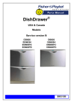
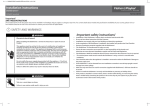
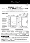
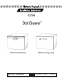
USA DS602 (Prefinished) Part No. 599066/D DS602I (Integrated) Models DS602 DS602I Single DishDrawer Table of Contents Section 1 1.1 1.2 1.3 1.4 1.5 1.6 Section 2 2.1 2.2 2.3 General Information Preparation Product Specifications & Cavity Dimensions Options for Installing Multiple Products Electrical, Plumbing & Drainage Information Product Parts Additional Product Parts for Integrated DishDrawer Fitting the DishDrawer DishDrawer Mounting Hole Locations Connecting the Services Flexible Extrusion Attachment for 24 Cavity Section 3 Inserting DishDrawer Into Cavity Section 4 Information for Cabinet Maker for Integrated DishDrawer 4.1 Section 5 5.1 5.2 5.3 5.4 5.5 Integrated Drawer Front Dimensions Integrated Drawer Front Installation Changing the Integrated Badge Enclosure Disassembling the Integrated Badge Assembly Assembling the Integrated Badge Fitting the Badge, Handle & Mounting Panel to the Drawer Front Fitting the Drawer Front to the DishDrawer Section 6 Final Fitting For Single DishDrawer Section 7 Final Checks 7.1 7.2 Installation Wet Test Troubleshooting Page DS_01 SECTION 1 GENERAL INFORMATION STEP 1.1 PREPARATION NOTE TO THE INSTALLER n Be sure to leave these instructions with the Customer. n Ensure this appliance is properly grounded. NOTE TO THE CONSUMER n Keep these Installation Instructions with your Use & Care Manual for future reference. IMPORTANT n Read these Instructions completely and carefully. n Observe all governing Codes and Ordinances. WARNING n These Instructions are intended as a guide only. n It is the responsibility of the plumber and electrician to ensure that each installation complies with all Codes and Ordinances. n Installation of this DishDrawer requires basic mechanical and electrical skills. n The installer is responsible for the DishDrawer installation. Improper installation is not covered under the Express Warranty Form. IMPORTANT n At the completion of the DishDrawer installation, the Installer must perform Final Checks as per Section 7 of these Installation Instructions. n Ensure the DishDrawer enclosure is prepared for installation. n Remove all packaging and materials supplied with the DishDrawer. n If you have any questions concerning the installation of this DishDrawer, contact: Fisher & Paykel Customer Care Centre TOLL FREE 1-888-9-FNP USA TOLL FREE 1-888-9-367 872 Fax (949) 829 8699 WWW.FISHERPAYKEL.COM 27 Hubble Irvine CA 92618 USA WARNING Before installing the DishDrawer, remove the house fuse or open the circuit breaker. Ensure all water connections are turned OFF. WARNING The DishDrawer MUST be installed to allow for future removal from the enclosure if service is required. STEP 1.2 PRODUCT SPECIFICATIONS & CAVITY DIMENSIONS Weight - Full - Empty Electrical Drying Water Connection Water Pressure 93lb (42kg) Prefinished (Water pressure below 7 p.s.i. (50 kpa) 62lb (28kg) Prefinished may require the electronics to be re-programmed by a Service Person 110-120VAC at the time of installation.) 3 pin socket outlet Residual Heat & Fan Assisted Recommended Hot 140°F (60°C) Max. Maximum 139 p.s.i. (960 kpa) Minimum 4.3 p.s.i. (30 kpa) Page DS_02 IMPORTANT STEP 1.3 OPTIONS FOR INSTALLING MULTIPLE PRODUCTS Where the DishDrawer is in an under counter situation, i.e. built into a kitchen unit, it is recommended that bare wood surrounding the DishDrawer is sealed with an oil based paint or polyurethane to prevent possible steam damage. IMPORTANT If mounting the DishDrawer near the bottom of the cabinet, ensure there is adequate room underneath the supporting cabinet to tighten bolts. STEP 1.4 ELECTRICAL, PLUMBING & DRAINAGE INFORMATION ELECTRICAL Care should be exercised when the appliance is installed or removed, to reduce the likelihood of damage to the power supply cord. IMPORTANT If the power supply cord is damaged, it must be replaced by the Manufacturer, its Service Ensure the cavity sides are Agent or a similarly qualified person, in order to avoid a hazard. plumb (vertical) as this will assist with leveling the The power supply receptacle for the appliance should be installed in a cabinet or on a wall DishDrawer. adjacent to the under counter space in which the appliance is to be installed. IMPORTANT Ensure the Services Hole is as close as possible to the rear corner of the cabinet. The hole can be located on either side depending on the location of the services. IMPORTANT On corner installations ensure that there is a gap of 2" (50mm) minimum between the adjacent cabinetry and sides of drawers. The power supply receptacle should be positioned between 6" and 18" (150mm and 450mm) from the cabinet opening of the DishDrawer. GROUNDING INSTRUCTIONS This appliance must be grounded. In the event of malfunction or breakdown, grounding will reduce the risk of electric shock by providing a path of least resistance for electric current. This appliance is equipped with a cord having an equipment-grounding conductor and a grounding plug. The plug must be plugged into an appropriate outlet that is installed and grounded in accordance with all local Codes & Ordinances. PLUMBING - WATER SUPPLY a) b) c) d) Page DS_03 e) The water connection is to be made to a hot water supply only. Ensure the water temperature is not greater than 140°F (60°C). A readily accessible shut off valve must be installed in the supply pipe. The water supply pressure is to be between 4.3 p.s.i. minimum and 139 p.s.i. maximum. The inlet supply hose must be connected to the water supply using a 3/8" compression type water supply fitting. Ensure sealing washer supplied with connection hose is fitted. PLUMBING - DRAINAGE OPTIONS Option 1 Option 2 WARNING Improper connection of the equipment-grounding conductor can result in a risk of electric shock. Check with a qualified electrician or service representative if you are in doubt as to whether the appliance is properly grounded. Do not modify the plug provided with the appliance - if it will not fit the outlet, have a proper outlet installed by a qualified electrician. WARNING The Drain Hose Support must be at least 13 3/4" (350mm) above the base of the DishDrawer to prevent siphoning of the water during the wash cycle. Option 3 It is recommended that the Drain Hose Support is secured in place using the screw tab. Ensure that the drain hoses are fully extended. Note: DS602 Prefinished Model is shown. There is no variation in plumbing between DS602 Prefinished Model and DS602I Integrated Model. Options 1 and 2 are the preferred options. Page DS_04 Tools Needed To Install DishDrawer STEP 1.5 PRODUCT PARTS Wooden Chopping Board Level Safety Glasses Utility Knife Pencil Drill & Drill Bits (3/32", 9/16" & 11/32") (2.5mm, 12mm, 14mm) Sandpaper Tape Measure Square Ruler Phillips Screwdriver Pliers Adjustable Wrenches(x2) 7 /32" (6mm) Allen Key (Integrated Models) Router (Integrated Models) Jigsaw (Integrated Models) 1. 2. 3. 6. 5. 4. 7. 9. 8. 10. 1. 2. 3. 4. 5. 6. 11. Template (Single 1) Drain Hose Support (1) Screw (1) Wire Clip (1) M8 Bolts (4) Washers (4) 12. 7. 8. 9. 10. 11. 12. Single Connector (1) Edge Protector (1) Flexible Extrusion 2) Solderless Lug & Washer (1) Inlet Hose Washer (1) Hose Clamp (1) STEP 1.6 ADDITIONAL PRODUCT PARTS FOR INTEGRATED DISHDRAWER 13. 14. 15. 16. Mounting Bracket Nuts (4) Seal (1) Door Screws (4) Badge Kit (2) 13. 16. 15. 14. Page DS_05 FITTING THE DISHDRAWER SECTION 2 STEP 2.1 DISHDRAWER MOUNTING HOLE LOCATIONS 2.1.1 Draw the cavity center line on the supporting cabinetry. 2.1.2 TIP Ensure the cavity is at least 227/8" (580mm) deep. Center Template in cavity using V-notch on the front of the Template. IMPORTANT For Integrated product with door thickness other than 3/4 (18mm), the Template position must be adjusted forward or back to allow for this difference. 2.1.3 Align front of Template to suit surround of cabinetry. 2.1.4 Mark and drill four 15/32" - 9/16" (12mm-14mm) diameter holes as described on Template. Page DS_06 WARNING Ensure the edges of the Service Hole are smooth or covered. (See Step 1.2 Product Specifications & Cavity Dimensions.) If the Services Hole is through a metal partition, the hole must be protected with the Edge Protector provided. STEP 2.2 CONNECTING THE SERVICES 2.2.1 Feed the Power Cord, Inlet Hose and Drain Hose through the Services Hole. Position the DishDrawer in front of the opening. 2.2.2 Connect the Inlet Hose to the HOT WATER SUPPLY. Ensure the sealing washer supplied with the accessories is fitted. Hose coupling must be tightened a further half turn after seal contact. WARNING DO NOT adjust the length of the Inlet Hose. 2.2.3 TIP Turn the water valve ON to check for any leaks, before pushing the DishDrawer back into its cavity. If required, the Drain Hose may be trimmed to a suitable length. 2.2.4 If an air break option is not chosen, then the Drain Hose Support must be used and positioned at least 133/4 (350mm) above the base of the DishDrawer to prevent siphoning of the water during the wash program. (See Step 1.4 - Electrical, Plumbing & Drainage Information.) WARNING Attach the Drain Hose Support to the cabinet cabinetry to prevent siphoning and to keep the Drain Hose from kinking. Page DS_07 2.2.5 When using a standpipe option, hose should not extend further than 2 (50mm) down the standpipe in order to prevent siphoning. 2.2.6 If required, trim the Single Connector to the size which matches the waste tee or air break to be used. There are ribs provided to guide cutting. When using the Single Connector, the hose should be pushed in firmly, 5 clicks. WARNING The Product MUST NOT be plugged in at this stage. Remember to slip the Wire Clip over the Drain Hose before connecting to the Single Connector. The supplied Wire Clip should be installed between the two positioning ribs on the Single Connector. 2.2.7 Attach Single Connector to waste tee. Ensure snug fit using the supplied hose clamp. Ensure there is a power outlet in reach of the supplied flex. If there is not a suitable outlet available then have one installed by a qualified electrician. DO NOT modify the power plug supplied with the DishDrawer or use an extension cord, adaptor plug or multiple outlet box. 2.2.8 Alternatively, the DishDrawer may be permanently connected to flexible conduit. Remove the flex and cable clamp. Fit suitable cable clamp for the conduit and terminate the wiring as shown. WARNING If permanently connecting, ensure power is isolated. Use the solderless lug and washer supplied with the product parts to terminate the ground wire. Page DS_08 TIP Wiring, Plumbing and Services should be completed before attaching the flexible extrusion. STEP 2.3 FLEXIBLE EXTRUSION ATTACHMENT FOR 24 (610mm) CAVITY 2.3.1 Flexible Extrusions are supplied to enable the installer to help fill any excess space between the sides of the DishDrawer and the cavity. The two lengths of Flexible Extrusion (supplied) should be attached before pushing the DishDrawer into the cavity for final installation. This Extrusion is designed to fit a 24 (610mm) width cavity. 2.3.2 Open the drawers, exposing the chassis trim. 2.3.3 Remove backing from adhesive tape on Flexible Extrusion. 2.3.4 Apply as per drawings, ensuring the curved edge of the Flexible Extrusion fits around the corner of the chassis trim. 2.3.5 When checking final fit, ensure DishDrawer is centered and there are even tolerances between DishDrawer and cavity. Page DS_09 INSERTING DISHDRAWER INTO CAVITY 3.1.1 Position product to suit joinery ensuring hoses are not kinked or cut. SECTION 3 WARNING DO NOT push against the middle of the drawer. IMPORTANT 3.1.2 Make sure the inlet and drain hose and main flex are not restricted or damaged by carefully pulling them through the Services Hole as the DishDrawer is being pushed back into the cavity. Insert M8 bolts and washers through holes in shelf. WARNING The DishDrawer should not support any part of the kitchen cabinetry. 3.1.3 Ensure product is correctly positioned and aligned before tightening. Refer to Step 7.1 - Installation Wet Test. Page DS_10 SECTION 4 I N T E STEP 4.1 INTEGRATED DRAWER FRONT DIMENSIONS IMPORTANT 4.1.1 Recommended Drawer Front thickness for Integrated product is 5 /8" to 3/4" (16mm - 18mm). G R A T E D P R O D U INFORMATION FOR CABINET MAKER FOR INTEGRATED DISHDRAWER IMPORTANT Drawer Front material must be suitable for damp conditions or adequately sealed to withstand moisture. Additional protection can be provided by using a Moisture Resistant Board. IMPORTANT Allow for any obstructions at the top of the cavity when allowing for space between the countertop and DishDrawer. C T O N L Y Page DS_11 Use the following diagrams to work out the dimensions for the Integrated Panels for Drawer Fronts. IMPORTANT A minimum clearance of 3 /32 (2.5mm) must be maintained between the Drawer Front and existing cabinetry, except between the underside of the Drawer Front and the shelf, where a 1/4 (6mm) clearance is needed for product venting. I N T E G R A T Drawer Front Air Flow Chamfer Chamfer the back of the Drawer Front Panel at the bottom as shown, to enhance air flow. E D P R O D U 4.1.2 Use the following diagrams if installing the DishDrawer at floor level. C T O N L Y Page DS_12 I N IMPORTANT 4.1.3 Control Badge Position All marking out to be Badge can be located anywhere within the Mounting Zone shown. Handle position will need done on the back surface to be taken into account. of the Drawer Front. T E G R A T E D IMPORTANT When mounting the handle, ensure fastenings do not protrude beyond the back surface of the Drawer Front. P R O D U C IMPORTANT Accuracy is essential when cutting the Badge Mounting Hole to ensure a neat fit to hold the badge. 4.1.4 Badge Cutout Dimensions Cut out Badge Mounting Hole in the chosen position (see Control Badge Mounting Zone on diagram above). A Control Badge Template (Part No. 526253) is available on request from Fisher & Paykel or alternatively, a Template can be found on the Mounting Bracket enclosed with the product. T O N L The Badge Mounting Hole is an ellipse shape. Y Page DS_13 4.1.5 I Drawer Front Mounting Bracket Nut Holes Using a 11/32 (8.5mm) diameter drill bit, drill out the four screw holes in each door panel to a depth of 9/16 (14mm). Remove burrs. N T WARNING Use of a depth gauge is recommended when drilling out holes for Drawer Front Mounting Panel. E G R A T E CAUTION * These dimensions are important to ensure a 1/4 (6mm) airflow gap. Ensure the drill does not damage the face of the Drawer Front. D P R O D U C T O N L Y Page DS_14 SECTION 5 I N T E G INTEGRATED DRAWER FRONT INSTALLATION STEP 5.1 CHANGING THE INTEGRATED BADGE ENCLOSURE IMPORTANT To avoid electric shocks and damage to electronic components, the integrated badge should be disconnected from the DishDrawer when changing the badge enclosure. R There are several different colored Integrated badges to choose from. They include black, chrome, satin & brass. Two color options are provided with your machine, other options are available from your local Dealer. There are five parts to the Integrated Badge Assembly. They are as follows: 1. Integrated Badge 2. Button Badge 3. Light Pipe 4. Electronics Board 5. Badge Cover 6. Wires 5. 3. 1. 2. 4. 6. STEP 5.2 DISASSEMBLING THE INTEGRATED BADGE ASSEMBLY A 5.2.1 T Remove Badge Cover from the Integrated Badge. At the back of the Integrated Badge, slide the Badge Cover away from the wire terminals. E 5.2.2 Remove Electronics Board. Gently hold the wires to remove the Electronics Board. Care should be taken not to handle the front or back of the Electronics Board or touch inside the wire terminals. D 5.2.3 Remove the Light Pipe. Gently tap the Integrated Badge upside down on a hard surface until the Light Pipe comes away or insert a pen or pencil into the front side of the Integrated Badge to either one of the two small holes. P R 5.2.4 O Once you have removed the Electronics Board, Badge Cover and Light Pipe, you can assemble the electronics board into a badge of another color. D STEP 5.3 ASSEMBLING THE INTEGRATED BADGE U C 5.3.1 Button Badge T Insert the Button Badge into the back of the Integrated Badge. Do not break any of the buttons away from the Connection Runner. 5.3.2 Insert the Light Pipe into the Integrated Badge. Insert the Light Pipe with the circular ends into the small holes. O á Connection Runner N 5.3.3 Insert the Electronics Board with care, behind the Button Badge. When installing the Electronics Board, handle only the wires and do not touch the face or back of the Electronics Board or inside the wire terminals. 5.3.4 L Slide the Badge Cover into the slot on top of the Integrated Badge. Y Page DS_15 STEP 5.4 FITTING THE BADGE, HANDLE & MOUNTING PANEL TO THE DRAWER FRONT 5.4.1 Remove Drawer Front Mounting Panel by withdrawing pins from sides of drawers using long nosed pliers. 5.4.2 Slide Mounting Panel off in a downwards and outwards motion. WARNING Care should be taken in the following steps. CAUTION Take care not to damage front surface of panel. Ensure all cuts are straight and care is taken to avoid damage to the Drawer Front. I N T E G R A T E 5.4.3 Using an Allen Key, screw in Mounting Bracket Nuts. Remove Burrs. Screw in flush with back surface. 5.4.4 Fit the Door Mounting Panels using the screws supplied. D CAUTION Overtightening will damage the Drawer Front. P R O D U C 5.4.5 T Feed wires through to the back and press badge into hole. If needed, adhere badge to Drawer Front with a glue or silicon sealant. O 5.4.6 Fit the customer supplied handle. Refer to Step 4.1.3 - Control Badge Position. N L Y Page DS_16 I N T E G R A T E D P R O D U C T STEP 5.5 FITTING THE DRAWER FRONT TO THE DISHDRAWER TIP Use a small amount of liquid soap along the lip of the seal to aid the Drawer Front to slide on easily against the seal. 5.5.1 Fit seal to Drawer. CAUTION The rubber seal between the Drawer and Drawer Front must be kept in place. WARNING The Electronics Board is an electrostatic sensitive device. Ensure you are adequately grounded when connecting or disconnecting the badge by wearing a grounding strap or by grounding yourself to the DishDrawer. 5.5.2 Plug the grounding wire into the panel. Connect badge wires to integrated badge port on Electronics Board. 5.5.3 Fit Drawer Front by sliding in an upwards and inwards motion. WARNING Ensure the product is not plugged in. View of Slide Hooks CORRECT ü O 5.5.4 Ensure the slide hooks (on slide) are as far forward as possible as shown, then insert pins to lock in place, ensuring that the rib on the pin is vertical. Check fit of the Drawer Front and adjust if required. N L Y INCORRECT Page DS_17 û FINAL FITTING FOR SINGLE DISHDRAWER SECTION 6 6.1.1 Check final fit of DishDrawer in cavity. 6.1.2 Tighten M8 bolts. Page DS_18 SECTION 7 FINAL CHECKS STEP 7.1 INSTALLATION WET TEST 1. 2. 3. 4. 5. 6. 7. 8. 9. SECTION 12 Ensure product is level, securely fastened to the floor and opens and closes freely. Ensure inlet hose to faucet connection is tightened to specification. Ensure any knockouts or plugs in the drain connection have been drilled out and the drain connection made correctly. Plug in and turn ON the power and water supply. The DishDrawer should "beep" and light up. Open the drawers of the DishDrawer and check operation of Secondary Control Panel and check sprayarm is in place and free to rotate. Select Rinse program on the Secondary Control Panel and close the drawer. Start the Program by pressing the Start/Pause button. After the program has finished, check underneath the DishDrawer for water leakage. Ensure machine has run and drained correctly. Check water supply and drainage connection for leakage. STEP 7.2 TROUBLESHOOTING 1. 2. 3. 4. 5. 6. Water underneath DishDrawer, check the hose connections and hose for leaks. Water around water supply and drainage connections - check connections, existing plumbing and hoses for leaks. Excessive water remaining above the filter plate, after the rinse cycle, check for kinked drain hoses or blocked waste connection. No water supply, check water is on and there is water pressure. If a fault occurs, consult the Problem Solver Section of the Use & Care Manual. If unable to resolve, contact Customer Care Center. Ensure Power is connected and is switched ON. Ensure the water supply is connected and ON. Page DS_19 LEAVE ALL LITERATURE WITH THE CUSTOMER.