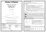
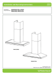
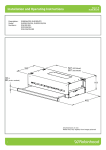
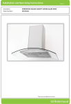
1
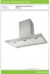
C A N O P Y
I N S T A L L A T I O N
I N S T R U C T I O N
O P E R AT I O N
Thank you for purchasing a quality stainless steel or iridium canopy rangehood. We have a
high standard of quality control and each rangehood is tested and approved before it leaves
the factory.
IMPORTANT: Please read prior to installation or operation
• A l w a y s s w i t c h p o w e r o ff p r i o r t o i n s ta l l i n g , s e r v i c i n g o r c l e a n i n g t h e a p p l i a n c e .
• Never use the appliance without filters.
• Please read the notes on general cleaning, especially the filters.
• Exhaust air must not be discharged into a heating flue or wall cavity, unless the cavity is
designed for that purpose.
• Areas where the rangehood is installed that also have gas, oil or coal fired heaters, must be
well ventilated to prevent a partial vacuum in the room. This includes gas hobs. (A
partial vacuum in the room could result in too high a concentration of gas in the air).
• The appliance is supplied with an approved power cable which must not be changed. If the
supply cord of this equipment is damaged, it must only be replaced by the manufacturer
or its service agent or similarly qualified person in order to avoid hazard.
APEX MODEL RH900 CQ SS
NZ/AUS Code
87947
UK Code
88793
EU Code
88955
APEX MODEL RH900 CM SM
NZ/AUS Code
87948
UK Code
88794
EU Code
88956
M A I N T E N A N C E
Particular care must be taken with grease filters which must be periodically cleaned (at
least every two months). Remove the grease filters and wash them either by hand or in the
dishwasher using mild detergent. In case of Charcoal Filter, it is a disposable item and
should be replaced when cleaning the rangehood. Use lukewarm water and mild detergent
to clean stainless steel components. In high humidity and coastal environments, cleaning
should be carried out frequently.
CAUTION: Never use abrasive or oil based liquid cleaners.
USE
Care and attention should always be taken when cooking with oils, alcohol, etc; which give
off flammable vapours.
Pre-used oil is especially dangerous in this respect.
Do not use uncovered electrical grill.
To avoid possible risks of fire always comply with the maintenance instruction above.
PLEASE READ THE ENTIRE INSTRUCTION BEFORE INSTALLING THE CANOPY
P R O D U C T
D I M E N S I O N S
330
290
When making the electrical connection, check that the socket has an earth connection and
that the voltage values correspond to those indicated on the rating plate inside the
appliance. The appliance must be positioned so that the electrial plug is accessible.
CONTROL PANEL
Left Push Button
Second Push Button
Third Push Button
Fourth Push Button
Fifth Push Button
780 min
1064 max
The unit is designed for 2.4 to 2.65 metre high ceiling. The decorative chimney cover
is telescopic and is designed for 665 to 950mm adjustment.
N o t e : D u c t i n g a c c e s s o r i e s a r e n o t s u p p l i e d . P l e a s e r e f e r t o t h e o p t i o n a l d u c t i n g k i ts .
The air outlet from the motor requires 150mm round ducting which requires 160mm
diameter round hole in the ceiling. This hole will be covered by the decorative
c h i m n e y. C a r e s h o u l d b e t a k e n t o a l i g n c a n o p y w i t h d e c o r a t i v e c h i m n e y a l l o w i n g
sufficient clearance to accommodate the flexible ducting.
115
21
897
Light On/Off Switch
Fan On High Speed
Fan On Second Speed
Fan On Low Speed
Fan Off
INSTALLATION OF UNIT
488
All Dimensions in mm
=
=
=
=
=
528
B e f o r e s ta r t i n g a s s e m b l y, r e a d t h e i n s t r u c t i o n s c a r e f u l l y a n d r e m o v e t h e f i l t e r s f r o m
canopy to allow access to wall mounting holes. To remove the filters, pull the relative
c a t c h a n d t i l t i n g i t d o w n w a r d s u n t i l i t d i s e n g a g e s f r o m t h e s u p p o r ts . R e v e r s e t h e s e
instructions when refitting the filters.
St a i n l e s s s t e e l / i r i d i u m i s v e r y e a s i l y d a m a g e d d u r i n g i n s t a l l a t i o n i f a b r a i d e d o r
knocked by tools.
104385 issue H
ECN: 04 036
L a m p
INSTALLATION OF THE UNIT
DUCTING
OPTION
R e p l a c e m e n t
a) Switch off the power to the rangehood.
RECIRCULATING
OPTION
b) Use a small bladed screwdriver to prise off the light cover (note slot).
2.4 TO 2.65 METRE HIGH CEILING
TOP
GUIDE
c) Use a cloth to remove the bulb. Do not touch the bulb with fingers.
d) Replace with a new bulb and “snap” the cover back into place.
A
200mm
e) Halogen bulb 12Volt/20Watt required.
700mm
UNDERSIDE OF HOOD
TO COOKING SURFACE
BULB
P a r t s
DUCTING
WARNING: The distance between the hob and the mounting holes of the canopy to be
at least 900mm to ensure that the fully installed canopy has a clearance of
700mm (recommended height) between the lower part of the hood and the
cooking hob. Before drilling any holes check the wall and the ceiling are clear of
any electrical cables, pipes etc. Fixing to a solid stud is recommended. A
Fix the mounting washers in position shown in diagram. 1
accross the washers to ensure they are level.
&
S e r v i c e
FILTERS
Aluminium Filter - No. R104163 (Ducted models)
Charcoal Filter No. R104165 (Recirculated models)
The use of charcoal filter is recommended on
recirculating model rangehoods.
RECIRCULATING
DUCTED
UNIDUCT FLEXI DUCT FIT is recommended.
1569 Flexi Duct Kit (150mm)
1
Rercirculating
Kit 89504
RECIRCULATED
Use manufacturer Part No. 89504
Check with spirit level
SEE DETAIL
6
INSTALLING DUCTING
NOTE: All ducting must comply with local requirements and building codes.
Mark the position of decorative chimney at ceiling and wall, cut cornice moulding
away if necessary to enable panels to fit flat against the wall and ceiling. 2 Mark
and cut the hole in the ceiling to fit the ducting (155 to 160mm dia). 3 This is
positioned centrally with the canopy and 100mm from the wall.
DETAIL 1
NOTE: TAB ON
BOTH SIDES TO BE
BENT IN TO LOCK
DUCT IN PLACE
For other Accessories, Parts or Service, please contact your local supplier.
(Refer to the Warranty Certificate)
INSTALLING CEILING BRACKET
Using the supplied screws, fix the ceiling bracket 4 to the wall, checking that it is
aligned with the hood.
WARNING
•
•
•
•
•
•
•
•
FINAL ASSEMBLY
Remove protective plastic covering from all parts including filters.
Now fit the canopy on the fixed mounting washers. 5 Plug in power
cord at power supply. Check function of rangehood light and motor,
before continuing assembly. Fix safety screw 5 connect 150mm
ducting 6 to top of motor flange secure with cable tie. Assemble
the telescopic ducting covers (chimney) 7 to accurately suit the
dimension required, 8 fit black plastic extrusion to the base and top
of the chimney and cut to length. 9 Mounting screws and plastic
cover caps are applied on top and bottom of the chimney.
•
•
This appliance is not intended for use by young children or infirm persons
without supervision.
Yo u n g c h i l d r e n s h o u l d b e s u p e r v i s e d t o e n s u r e t h a t t h e y d o n o t p l a y w i t h
the appliance.
There shall be adequate ventilation of the room when the rangehood is
used at the same time as appliances burning gas or other fuels.
Yo u m u s t r e a d t h e d e t a i l s c o n c e r n i n g t h e m e t h o d a n d f r e q u e n c y o f
cleaning.
There is a fire risk if cleaning is not carried out in accordance with the
instructions.
Do not flambé under the rangehood.
Exhaust air must not be discharged into an existing flue which is used
for exhausting fumes from appliances burning gas or other fuels.
The minimum distance between the hob surface and the lowest part of
the rangehood is 600mm.
This distance shall be at least 650mm
(recommended 700mm) if the rangehood is installed over a gas hob.
Attention should be given to ensure that any applicable regulations
concerning the discharge of exhaust air is fulfilled.
If the supply cord of this equipment is damaged, it must only be replaced
by the manufacturer or its service agent or similarly qualified person in
order to avoid a hazard.
MANUFACTURED FOR
BY:
ROBINHOOD LIMITED
RECOMMENDED UNIDUCT DUCTING
SYSTEMS FOR RANGEHOODS
6 ZELANIAN DRIVE, EAST TAMAKI
AUCKLAND, NEW ZEALAND
ISO9001 Certified
Electrical Rating:
346W (1.44A)
Max. at 230-240V 50Hz
104385 issue H
ECN: 04 036