Transcript
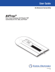
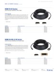
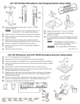
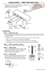
AVTrac™ Connectivity Box Installation Guide
Before installation of the AVTrac connectivity box, the base track must already
be installed. For full information about AVTrac installation, consult the
AVTrac Installation Guide. Install the connectivity box as follows:
Cover
End Plate
1. Remove the cover panel and end plates from the
connectivity box. One end has three mounting holes
in the base, the other has two. The end with three
holes faces toward the wall. Align the end with
two mounting holes with the end of the base
track.
3 Mounting Holes
2 Mounting Holes
End Plate
2. Mark where the holes in the bottom of the
connectivity box lie over the base track and,
using a 1/4" metal bit (not provided), drill at
least three holes through the track.
3. Using the provided masonry bit, drill 5/32" diameter
by 1 1/2" deep pilot holes into the concrete through the
predrilled holes in the track.
4. Reposition the connectivity box, in the correct orientation, over the
track (the end of the box with three holes must face back toward the wall). Using at least three of the provided
3/16" masonry screws, secure the box to the track and floor.
5. Populate the lid of the box with the required Architectural Adapter Plates and AC power modules. Run cabling
as necessary, and reattach the end plates and cover panel.
AVTrac™ Power Module Installation Guide
Before installation of the AVTrac Power Module, the AVTrac base track and
connectivity box must already be installed. For full information about AVTrac
installation, consult the AVTrac Installation Guide. Install the AC module as
follows:
To Main Circuit
C All electrical installation should be
US
AC Power
Module
Tabs
performed by qualified personnel in
accordance with local and national
electrical codes.
Conduit
W Switch off all electrical power before connecting
the AC conduit to a junction box, and keep power
off until installation is complete.
Junction Box
Studs
Black or Brown
(hot)
Slots
1. Install the power module at the end of the connectivity
box that is closest to the wall. Slide the side tabs into the slots on the side of
the connectivity box and mount the power module on the stud(s) in the floor of
the box (see the figure above right). Secure the module to the stud(s) by hand
tightening the provided 6/32" nut(s).
Green
or Green/Yellow
(ground)
2. Run the unattached end of the conduit and connect it to a convenient junction or
circuit box (see the figure at left). Extron recommends that the junction box be
directly wired to the main circuit.
White or Blue
(neutral)
AC Conduit
or Cable
C The module does not have a fuse and is rated at 15 A, maximum, for US modules and
10 A, maximum, for international modules.
Extron USA - West
Headquarters
From AVTrac AC
Power Module
+800.633.9876
Inside USA / Canada Only
+1.714.491.1500
+1.714.491.1517 FAX
Extron USA - East
Extron Europe
Extron Asia
Extron Japan
Extron China
Extron Middle East
+800.633.9876
+800.3987.6673
+800.7339.8766
+81.3.3511.7655
+81.3.3511.7656 FAX
+400.883.1568
+971.4.2991800
+971.4.2991880 FAX
+1.919.863.1794
+1.919.863.1797 FAX
+31.33.453.4040
+31.33.453.4050 FAX
+65.6383.4400
+65.6383.4664 FAX
Inside USA / Canada Only
Inside Europe Only
Inside Asia Only
Inside China Only
+86.21.3760.1568
+86.21.3760.1566 FAX
68-1617-01
Rev B
11 08