Transcript
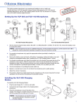
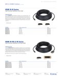
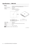
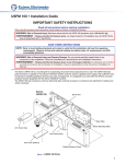
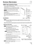
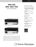
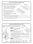
VLP 102 Pendant Microphone and Charging Station Setup Guide
Power
Indicator
LED
6
Top
4
5
1
3
7
1
2
a
Set the channel using the rotary switch. A and C = 2.3 MHz;
B and D = 2.8 MHz.
N
Each microphone must be on a different frequency. Set
the channel to C or D to disable the volume buttons.
b
c
Apply the Teacher or Student sticker to identify the microphone.
d
Attach the lanyard to the rotating clip. Adjust the lanyard to
position the microphone approximately 4" below the user's chin.
e
f
a
b
c
Remove the battery door, and insert the AA battery. Charge the
battery if necessary.
Plug the wall charger (5 V, 1 A) into a wall outlet.
Connect the wall charger's cable to the charging
station's power jack.
Place the microphone in one of the charger's slots, with
the charging contacts facing down. Charge for at least
6 hours.
N
Turn the microphone on by sliding the power switch up.
g
a
b
c
d
3
2
Speak in a normal tone of voice. Do not block the microphone
port opening.
The microphone can be left to charge for
extended periods. In maintenance mode, the
charge is retained when complete.
C
Do not charge alkaline or NiCd batteries.
Adjust the volume if necessary.
68-1631-01 Rev. A 01 09
VLR 102 IR Receiver and VLR 102SR Secondary Receiver Setup Guide
Cut a 2" to 3" diameter hole in the ceiling tile.
Align the center of the receiver housing with the hole in the ceiling tile.
Insert the mounting screw through the receiver housing and the hole in the ceiling tile.
4
Attach the Z-bracket to the end of the screw on the back side of the ceiling tile. Replace
the ceiling tile.
e
f
g
Set the Mix DIP switch to off and the Tone DIP switch to on (VLR 102 only).
h
i
Connect the other end of the Ethernet cable to the VoiceLift adapter for a VLR 102
Receiver, or to the RJ-45 jack labeled IN for a VLR 102SR Secondary Receiver.
1
Pull an Ethernet cable to the receiver location, and connect one end of the cable to the
RJ-45 jack (labeled OUT) on the receiver base.
Align the arrow on the dome's tab with the raised arrow on the edge of the housing.
Rotate the dome to the right (clockwise) until the arrow on the tab aligns with the
raised dot on the housing.
2
Connect the VoiceLift adapter to a PoleVault switcher.
RGB
1A
2A
VIDEO
3
RGB
In
Out
POWER
12V
3A MAX
VLR 102SR
VLR 102
I
N
P
U
T
S
O
U
T
P
U
T
S
1B
2B
4
AMPLIFIED OUTPUTS
LISTED 17TT
US AUDIO/VIDEO
®
Out
VIDEO
4/8
Ohms
APPARATUS
ON
HIGH
PASS
FILTER
STEREO
ON
OFF
AUX/MIX IN
DUAL
MONO
L
RS-232 MLC/IR
Tx Rx IR
12V
A B C
8
R
DC VOL
6
10V
VOL/MUTE
PoleVault Switcher
5
9
Extron USA - West
Headquarters
+800.633.9876
Inside USA / Canada Only
+1.714.491.1500
+1.714.491.1517 FAX
Extron USA - East
Extron Europe
Extron Asia
Extron Japan
Extron China
Extron Middle East
+800.633.9876
+800.3987.6673
+800.7339.8766
+81.3.3511.7655
+81.3.3511.7656 FAX
+400.883.1568
+971.4.2991800
+971.4.2991880 FAX
+1.919.863.1794
+1.919.863.1797 FAX
+31.33.453.4040
+31.33.453.4050 FAX
+65.6383.4400
+65.6383.4664 FAX
Inside USA / Canada Only
Inside Europe Only
Inside Asia Only
Inside China Only
+86.21.3760.1568
+86.21.3760.1566 FAX
VoiceLift
Adapter
8
O 1
N
2
CTS-2
TONE
MIX
3
7