1
User’s Manual
RGB 302/304
Universal Digital Interface
Contents
Chapter One • Introduction to the RGB 302/304
RGB 302/304 Features ......................................................... 1-1
SmartSave™ .......................................................... 1-2
LCD Menu Driven Controls ..................................... 1-2
Memory Blocks and Memory Cycling ...................... 1-2
Level Control (picture) ............................................. 1-2
Peaking Control (sharpness) ................................... 1-3
Horizontal Shift Control (centering) .......................... 1-3
Vertical Shift Control (centering) .............................. 1-3
Automatic Sync Output Detection ........................... 1-3
Automatic Sync Stripping ........................................ 1-3
Keyboard Lockout ................................................... 1-3
Auto-switching Power Supply .................................. 1-3
Audio Interface ........................................................ 1-3
DIP Switch Settings ................................................ 1-4
RS-232 Control Interface for Remote Control .......... 1-4
Benefits of Windows RGB 302/304 Software .......... 1-4
Front Panel Controls .............................................................. 1-5
Menu button ............................................................ 1-5
Cursor buttons ........................................................ 1-5
Next button ............................................................. 1-5
LCD Display ........................................................... 1-5
RGB 302/304 Specifications .................................................. 1-6
Chapter Two • Installing the RGB 302/304
Easy Setup Procedure .......................................................... 2-1
Rear Panel DIP Switch Settings ............................................ 2-3
Audio Connections ................................................................ 2-3
Installation Check .................................................................. 2-4
Memory Cycling Feature ....................................................... 2-5
Preset Memory Blocks .......................................................... 2-6
Power Supply ........................................................................ 2-6
RS-232 Interface Specifications ............................................ 2-6
Application Diagrams ............................................................. 2-7
Chapter Three • Front Panel Menus
RGB 302/304 Menu Sequence .............................................. 3-1
Using the Menu System ........................................................ 3-2
Default Cycle Menus ............................................................. 3-3
Default Cycle Hot Keys ........................................... 3-4
Language Menu ...................................................... 3-4
Keyboard Lock/Unlock Menu .................................. 3-5
Digital Display Sync Processing ............................. 3-5
Image Controls Menus .......................................................... 3-6
Horizontal Shift Menu .............................................. 3-6
Vertical Shift Menu .................................................. 3-6
Level Control Menu ................................................. 3-7
Peaking Control Menu ............................................. 3-7
Extron RGB 302/304 Universal Interface • User’s Manual
Page i
Contents
Sync Controls Menus ............................................................ 3-8
Sync Output Menu .................................................. 3-8
Horizontal Polarity Menu ......................................... 3-9
Vertical Polarity Menu ............................................. 3-9
Option Controls Menus ........................................................ 3-10
LCD Backlite Menu ............................................... 3-10
Memory Cycling Menu .......................................... 3-10
System Reset Menu ............................................. 3-10
Confirm Reset Menu ............................................. 3-11
Exit Menu ............................................................................ 3-11
Default Settings on Power Up .............................................. 3-11
Default Settings on System Reset ....................................... 3-11
Chapter Four • Using the Windows® Control Program
Installing Windows® Control Software ................................... 4-1
Normal Windows Control Panel ............................................. 4-2
RGB 302/304 Help ................................................................ 4-3
Appendix A • Programmer’s Guide
Remote Control Port (RS-232) .............................................. A-1
Host-to-RGB 302/304 Instructions ........................................ A-2
Simple Commands ................................................................ A-3
Error Codes .......................................................................... A-4
RGB 302/304-Initiated Messages .......................................... A-5
RGB 302/304 User’s Manual
68-354-01
First Edition
89-03
Written and printed in the USA
Page ii
Extron RGB 302/304 Universal Interface • User’s Manual
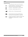
Legend
Legend of Icons
The following icons may be used in this manual:
______ Important information – for example, an action or a
step that must be done before proceeding.
______ A Warning – possible dangerous voltage present.
______ A Warning – possible damage could occur.
___ A Note, a Hint, or a Tip that may be helpful.
____ Possible Electrostatic Discharge (ESD) damage
could result from touching electronic components.
_____ Indicates word definitions. Additional information may
be referenced in another section, or in another
document.
Extron RGB 302/304 Universal Interface • User’s Manual
Page iii
Notes
____
Page iv
Extron RGB 302/304 Universal Interface • User’s Manual
RGB 302/304 Universal Digital Interface
User’s manual
1
Chapter One
Introduction to the RGB 302/304
SmartSave™
LCD Menu Driven Controls
Memory Blocks and Memory Cycling
Image Display Controls
Automatic Sync Output Detection
Keyboard Lockout
RS-232 Control Interface
Front Panel Controls
Specifications
Extron RGB 302/304 Universal Interface • User’s Manual
Chapter 1 • Introduction to the RGB 302/304
The Extron RGB 302/304 is a digitally controlled
Universal Analog/ECL Computer-Video Interface. It
can connect most computers to a video presentation
device, such as a large screen projector or data
monitor. The RGB 302/304’s SmartSave™ feature
automatically selects sync settings and other
parameters for a quick and easy setup.
Among the RGB 302/304 features are RGB input/
output connectors, an MBC power jack, audio input/
output connectors, an RS-232 connector, and rear
panel DIP switches.
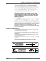
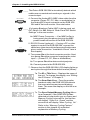
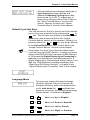
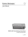
The RGB 304 is identical in performance and features
as the RGB 302 with the exception being that, unlike
the RGB 302, the RGB 304 has its 9-pin Analog/ECL
input, Audio input, and MBC power jack located on the
front panel of the unit, as shown below. This difference
allows the RGB 304 to be installed in situations where
front panel access to such connectors may be
necessary, such as the mounting of the unit in a rack
mount environment.
RGB 302/304 Features
The RGB 302/304 features allow video output to be
controlled in several ways:
• Automatic sync output detection and setup for quick
installation
• Custom setup and adjustments made from the Front
Panel (shown below)
• RGB 302/304 Windows® software, through an RS-232
interface
• User-written programs through the RS-232 port
RGB 302
MENU
NEXT
RGB 304
MBC
AUDIO IN
ANALOG/ECL
MENU
POWER
Page 1-1
NEXT
INPUT
Extron RGB 302/304 Universal Interface • User’s Manual
Chapter 1 • Introduction to the RGB 302/304
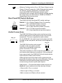
SmartSave™
This unique feature greatly simplifies the video
configuration setup of the RGB 302/304. The
RGB 302/304 comes preset with various video
configurations to match most computer video
requirements. The proper configuration is
automatically selected and implemented for the user.
In addition, the RGB 302/304 will automatically save
any user modifications to the video configuration and
will recall the correct configuration without need for
user intervention.
LCD Menu Driven Controls
The RGB 302/304 does not have front panel “knobs”
or “switches” to control its operation. Instead, the
“controls” are displayed and adjusted using the Front
Panel LCD display and the six front panel buttons.
The Front Panel display can be used in any of four
languages: English, French, Spanish and German.
The display serves two purposes:
1. The RGB 302/304 automatically detects and
displays vital troubleshooting information, such as
the horizontal and vertical scan frequencies.
2. The user can step through and display any of the
controls or features in the interface.
___ Chapter 3 has details on using the Front Panel.
Memory Blocks and Memory Cycling
There are 15 preset memory blocks which store video
format information, such as video, sync and control
settings. Each block is preloaded by Extron and
defines one video configuration (e.g. VESA3, MAC16",
etc.). These preset memory blocks define most video
requirements. In addition, there are 25 user-definable
memory blocks available.
The RGB 302/304 automatically cycles through
(Memory Cycling) the user-defined memory blocks
and loads the video format that most closely matches
the computer’s video output. Should a match not be
found, the 15 preset memory blocks are searched
next (refer to the section “Memory Cycling Feature” in
Chapter 2).
Level Control (picture)
This feature is similar to the brightness control on a
data monitor and is used to adjust the intensity of the
video level on the projector/monitor screen by using
the cursor keys. There are 255 levels for this control.
Extron RGB 302/304 Universal Interface • User’s Manual
Page 1-2
Chapter 1 • Introduction to the RGB 302/304
Peaking Control (sharpness)
This control is similar to the sharpness control on a
data monitor. It is also used to compensate for long
cable runs. There are eight Peaking levels which are
selected by using the cursor keys.
Horizontal Shift Control (centering)
This feature shifts the displayed image to the left or
right on the projector/monitor screen by using the
cursor keys. There are 255 positions for this control.
Vertical Shift Control (centering)
This feature shifts the displayed image up or down on
the projector/monitor screen by using the cursor keys.
There are 255 positions for this control.
Automatic Sync Output Detection
The RGB 302/304 automatically detects which cables
are connected and sends either Sync On Green,
Composite Sync or Separate Horizontal and Vertical
sync signals to the correct output cables. This
function can be overridden through menu controls.
Automatic Sync Stripping
The RGB 302/304 automatically strips all incoming
sync from the red, green, and blue channels for clean,
crisp signal processing. Sync may be recombined with
the green channel if necessary.
Keyboard Lockout
The RGB 302/304 features a Keyboard Lockout
function which allows the user to “lock out” the front
panel controls by using “hot keys”. This feature
disables front panel operation after setup.
Auto-switching Power Supply
The RGB 302/304 is equipped with an internal autoswitching power supply that operates from any input
voltage in the 100 to 240 VAC, 50/60 Hz range. No
equipment changes are necessary.
Audio Interface
The RGB 302/304 includes a PC/computer audio (600
ohm) to line-level audio (balanced) converter. For
computers which have a sound card, the audio
interface will process the audio signal along with the
video (audio follow). The audio output can be
connected to an external stereo system.
Page 1-3
Extron RGB 302/304 Universal Interface • User’s Manual
Chapter 1 • Introduction to the RGB 302/304
DIP Switch Settings
The RGB 302/304 includes a rear panel DIP switch
bank which will activate Digital Display Sync
Processing, remove/pass serration pulses, and set 75
Ohm/high impedance video input termination.
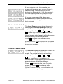
RS-232 Control Interface for Remote Control
The RGB 302/304 has a built-in RS-232 interface to
allow the unit to be controlled remotely in either of two
ways:
1. Use the Windows® RGB 302/304 Control Panel
software provided by Extron (see next section).
2. The user may write software to control the RGB 302/
304 from a PC or control system. See the
Programmer’s Guide in Appendix A.
The RS-232 protocol is fixed at 9600 baud, no parity, 8
data bits and 1 stop bit.
Benefits of Windows® RGB 302/304 Software
Using the Windows® software provided with the
RGB 302/304 adds several advantages over Front
Panel operation.
• All of the controls are quick and easy to use with
the on-screen control panel.
• Application setups can be stored as disk files,
therefore, an unlimited number of setups can be
stored and reloaded from the PC’s hard drive or
floppy disk.
Refer to Chapter 4 for details on using this software.
Extron RGB 302/304 Universal Interface • User’s Manual
Page 1-4
Chapter 1 • Introduction to the RGB 302/304
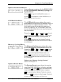
Front Panel Controls
The Front Panel buttons (as shown below) have many
functions, depending on which menu is accessed at
any particular time. For example, the user can display
and adjust controls to modify the video display. The
specific functions for these buttons are described
below.
RGB 302
MENU
NEXT
RGB 304
AUDIO IN
ANALOG/ECL
MBC
MENU
POWER
NEXT
INPUT
The LCD panel cycles through 3 default menus when
the RGB 302/304 is first powered on. Refer to Chapter
3 for instructions on using the RGB 302/304 menus.
___ There is a built-in time-out function which will return to
the default menu cycle if no buttons are pressed for
approximately 8 seconds. By default, any changes
which were made will be automatically saved upon the
time-out.
Menu button
MENU
The Menu button is used to select and step through
the four different menu classes (to be explained in
Chapter 3).
Next button
NEXT
The Next button is used to advance to the next
submenu of a menu class or to return to the beginning
of the menu class (see the menu flowchart on page 3-1).
Cursor buttons
The cursor buttons are typically used to step through
the menu options before making a choice. These
options could be alpha characters or numeric settings.
The user may also want to change the value of the
current setting (i.e., increase or decrease level, shift,
peaking, etc.). These buttons also serve as
convenient “hot keys” to various functions.
LCD Display
Besides displaying the menus, the LCD display
provides some helpful information, such as which
buttons to use when making choices.
Page 1-5
Extron RGB 302/304 Universal Interface • User’s Manual
Chapter 1 • Introduction to the RGB 302/304
RGB 302/304 Specifications
Part Number
.. 60-243-01 (RGB 302)
.. 60-244-01 (RGB 304)
User’s Manual
.. 68-354-01
Dimensions
.. 8.75" W x 9.5" D x 1.75" H
Shipping Weight
.. 5 lbs
Input Power
.. 100 - 240 VAC, 50/60 Hz,
auto-switchable, internal
Power Consumption
.. 17 watts
Operating Temperature
.. 0° C to 50° C
Control Baud Rate
.. 9600 baud
Input Signal:
Video .. 2V p-p max
Video Impedance .. 75 Ω terminated, 7.5 kΩ untermin.
Sync .. Separate H & V Sync TTL (±)
.. Composite H & V TTL (±)
.. Sync on Green (-).3V
.. Sync on Red, Green & Blue (-).3V
Sync Impedance .. 10 kΩ
Audio .. Connector: 3.5 mm jack
Audio Impedance .. High Z
Output Signal:
Video .. .35V to 1V p-p with .7V applied
Video Impedance .. 75 Ω
Sync .. Sync on Green (-)
.. Composite Sync (-)
.. Separate H & V (±)
Sync Impedance .. 75 kΩ
Audio .. Connector: 3.5 mm jack
Audio Impedance .. 600 Ω
Frequency Compatability:
Horizontal .. 15 - 125 kHz (automatically)
Vertical .. 30 - 170 Hz (automatically)
RGB Video Bandwidth .. 220 MHz (2 ns rise time)
LCD Scan Rate Range:
Horizontal .. 15 - 150 kHz
Vertical .. 30 - 170 Hz
LCD Menu (Front Panel): .. Back-lit alphanumeric display
(English, German, Spanish or
French)
Warranty
.. Two years, parts and labor
Extron RGB 302/304 Universal Interface • User’s Manual
Page 1-6
Chapter 1 • Introduction to the RGB 302/304
____
Page 1-7
Extron RGB 302/304 Universal Interface • User’s Manual
RGB 302/304 Universal Digital Interface
User’s manual
2
Chapter Two
Installing the RGB 302/304
Easy Setup Procedure
DIP Switch Settings
Audio Connections
Installation Check
Memory Cycling Feature
RS-232 Specifications
Extron RGB 302/304 Universal Interface • User’s Manual
Chapter 2 • Installing the RGB 302/304
RGB 302
MENU
100-240V
NEXT
0.5A
RS-232
G
B
H/HV
DDSP
SER REM
75 OHM
OUTPUT
R
V
AUDIO
L
MBC
R
POWER
50/60 Hz
OUT
ANALOG/ECL
INPUT
IN
RGB 304
AUDIO IN
ANALOG/ECL
MBC
MENU
POWER
100-240V
NEXT
INPUT
0.5A
G
B
H/HV
V
AUDIO
L
50/60 Hz
DDSP
SER REM
75 OHM
OUTPUT
R
RS-232
R
OUT
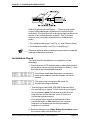
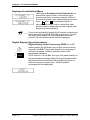
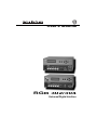
____ The diagrams above show the front and rear panels of
the RGB 302 (top pair) and RGB 304 (bottom pair).
Easy Setup Procedure
These easy-to-follow steps describe the general setup
of the RGB 302/304. Refer to the example Application
Diagrams at the end of this chapter.
1. Turn the computer and monitor power Off.
Do not connect the RGB 302/304 power cable yet
(there is no power switch).
2. Disconnect and remove the computer’s local monitor
video cable from the computer video port.
3. Connect BNC output cables from the RGB 302/304
to the data monitor/projector — all BNC outputs are
RGB analog. The BNC connectors are marked R, B,
G, H/V and V. They may be connected in any of
three ways:
• Red, Green/sync and Blue, for RGB with sync on
Green. (3-cable hookup)
• Red, Green, Blue and H/HV, for RGB with Composite
sync signals. (4-cable hookup)
• Red, Green, Blue, H/HV and V, for RGB with separate
Horizontal and Vertical sync signals. (5-cable hookup)
Page 2-1
Extron RGB 302/304 Universal Interface • User’s Manual
Chapter 2 • Installing the RGB 302/304
____ The Extron RGB 302/304 automatically detects which
cables are connected and sends sync signals to the
correct output.
ANALOG/ECL
INPUT
4. Connect the Analog/ECL MBC video cable from the
computer (Power PC, PC, Mac, or workstation) to
the Analog/ECL Input connector on the RGB 302/
304 and to the local monitor. See note below.
____ If a Laptop Breakout Cable (LBC) is being used, set
DIP Switch 3 to Off. Refer to “Rear Panel DIP Switch
Settings” in the next section.
4a. MBC Power Connector — If an MBC buffer is
being used, plug the phone jack into the MBC
power female connector of the RGB 302/304.
RS-232
5. RS-232 Control (optional) — If using a PC or other
system to control the RGB 302/304, connect the
cable here (pinouts and interface specifications are
given under the section “Installation Check” later in
this chapter).
6. Turn power On at the local computer monitor. Next,
turn power On at the computer supplying the video
input — (Power PC, PC, Mac or workstation).
6a. Turn power On at the data monitor/projector.
6b. Connect power to the RGB 302/304.
7. Observe that the RGB 302/304 LCD display lights up
and cycles through the three default menus (below).
7a. The ID or Title Menu - Displays the name of
the unit. To change this display, see “Editing
the ID Screen” in Chapter 3.
7b. The Scan Rate Menu - From the monitor
breakout cable, the RGB 302/304 detects
the scan rate frequencies and displays
them. The scan rate display on the left is an
example.
7c. The Sync Output-Memory Cycling Menu As an example, if the RGB 302/304 has
detected an output with sync on Green and
Memory Cycling is turned On, the first line
will display “Sync Out: Green” and the
second line will display “Mem Cycling: On” .
Refer to the “Memory Cycling Feature”
section in this chapter for a detailed
explanation of Memory Cycling.
Extron RGB 302/304 Universal Interface • User’s Manual
Page 2-2
Chapter 2 • Installing the RGB 302/304
____ Memory Cycling can be On or Off. Sync Output can be
Green, Comp (Composite), H&V (Separate Horizontal
& Vertical), or Auto (Automatic). Automatic Sync
means the RGB 302/304 detects which output
connectors are currently active and will set and display
the output sync as either Green, RGBS or RGBHV,
depending on the connections.
Rear Panel DIP Switch Settings
On
Off
DDSP
SER REM
75 OHM
The RGB 302/304 has three DIP switch settings:
Switch 1: On = Digital Display Sync Processing
Off = Processed sync (normal)
1 2 3
Switch 3: On = 75-Ohm input termination
Off = High impedance input termination
Switch 2: On = Remove serration pulses
Off = Pass serration pulses (normal)
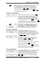
Audio Connections
The RGB 302/304 provides audio interfacing to the
audio output which is connected to the user’s audio
equipment. The user supplies the audio cables.
RGB 302
AUDIO
L
R
OUT
IN
On the RGB 302, the audio input and output are both
located on the rear panel, as shown in the diagram to
the left.
RGB 304
The RGB 304 has the audio output
located on the rear panel, but the
audio input is situated on the front
panel, as shown to the right.
AUDIO
L
R
OUT
AUDIO IN
The audio interface is a PC/computer audio (600 Ω) to
line-level audio (balanced) converter. If the computer
has a sound card, the RGB 302/304 will distribute the
audio with the video (audio follow).
Although the input and output audio connectors are
physically the same, they are used differently. See the
illustration and the following descriptions for the
correct wiring of audio inputs and outputs.
Audio Input — Connect the stereo audio sources to
Audio In. Input cables should be wired as follows:
• Stereo left to Tip (+) contact
• Stereo right to Ring (-) contact
• Both commons to Sleeve (Gnd) contact
Page 2-3
Extron RGB 302/304 Universal Interface • User’s Manual
Chapter 2 • Installing the RGB 302/304
Audio Output (Left and Right) — There is one audio
output using separate connectors for left and right
channels. Connect the left and right output jacks to the
inputs of an external audio system. The 3-contact
outputs can be wired for balanced or unbalanced
audio.
• For unbalanced audio, use Tip (+) and Sleeve (Gnd)
• For balanced audio, use Tip (+) and Ring (-)
____ Observe polarity when making connections to keep left
and right channels in phase.
Installation Check
To verify that the installation is complete, do the
following:
1. Check that the LCD default menus show the correct
information (as previously described in Step 7). Use
the menus as a troubleshooting aid.
If no video input was detected, no memory
block was loaded, and the display will show
zeroes.
The scan rate menu may be used for
troubleshooting as follows:
• The timing for the RGB 302/304 is derived from
the vertical sync signal. If the vertical sync signal
is not present, both the vertical and horizontal
frequencies will be zeroes, even if there is a
horizontal signal present.
• If a vertical sync signal is detected and the
horizontal sync is not detected, the vertical
frequency is displayed, but the horizontal
frequency is zeroes.
2. Recheck the previous Easy Setup Procedure steps
for correct cable connections, etc.
Extron RGB 302/304 Universal Interface • User’s Manual
Page 2-4
Chapter 2 • Installing the RGB 302/304
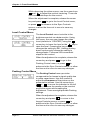
Memory Cycling Feature
The RGB 302/304 is preset at the factory with fifteen
video formats which are stored in memory blocks.
These memory blocks contain video formats which
will match most computers. There are also 25
additional empty memory blocks which are userdefined.
When a video input is connected and the RGB 302/
304 is powered On, the 25 user-defined memory
blocks are scanned (cycled) sequentially for a
configuration which matches the computer’s video
input. If a match is found, that format’s stored settings
are implemented. If a match is not found, the 15 preset
video formats are scanned next. If a match is found,
that format and any adjustments to the image are
automatically saved to a user-defined memory block (if
Memory Cycling is set On). If a match is not found
among the preset formats, a new video format will be
created and stored (see note below) as a user-defined
memory block.
The 25 user-defined memory blocks are filled
sequentially (1 to 25). If the last empty memory block
(#25) has already been filled and a new video format is
added, memory block #1 will be overwritten. Additional
new formats will sequentially overwrite memory blocks
#2, #3, #4, etc., and start over again at memory block
#1, #2, #3, etc.
The 15 preset memory blocks are permanently stored,
while the 25 user-defined memory blocks can only be
cleared by resetting the RGB 302/304 (refer to
System Reset Menu in the “Option Controls Menus”
section of Chapter 3). Powering Off the RGB 302/304
will not delete any of the memory blocks.
____ If Memory Cycling is disabled (set Off), any changes to
a video configuration will not be stored in a memory
block and no new memory blocks will be saved. Refer
to Memory Cycling Menu in the “Option Controls
Menus” section of Chapter 3.
Page 2-5
Extron RGB 302/304 Universal Interface • User’s Manual
Chapter 2 • Installing the RGB 302/304
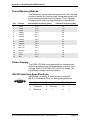
Preset Memory Blocks
The Memory Cycling feature supports 25 user-defined
memory blocks for storing video configurations and 15
permanently defined memory blocks. The 15 preset
memory block video configurations are listed below.
No. Format
Horizontal Frequency [kHz]
Vertical Frequency [Hz]
1
VGA1
31.5
70
2
VGA2
31.5
70
3
VGA3
31.5
60
4
VESA1
35.2
56
5
VESA2
37.9
72
6
VESA3
48.4
60
7
VESA4
56.4
70
8
VESA5
38.0
60
9
VESA6
48.0
72
10
Mac 13"
35.0
67
11
Mac 16"
49.7
75
12
Mac 21"
68.7
75
13
Sun1
71.7
76
14
Sun2
81.0
76
15
SGI
63.9
60
Power Supply
The RGB 302/304 is equipped with an internal autoswitching power supply that operates from any input
voltage in the 100 to 240 VAC, 50/60 Hz range. No
equipment changes are necessary.
RS-232 Interface Specifications
RS-232
9600 baud, no parity, 8 data bits and 1 stop bit.
RS-232 Connector Pins are assigned as follows:
Pin Signal
1
—
2 Transmit
3 Receive
Pin
4
5
6
Signal
—
Ground
—
Extron RGB 302/304 Universal Interface • User’s Manual
Pin
7
8
9
Signal
—
—
—
Page 2-6
Chapter 2 • Installing the RGB 302/304
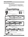
Application Diagrams
The diagrams below show possible application setups
for the RGB 302 and RGB 304.
RGB 302
Control
System
LCD SYNC
SER REM
75 OHM
32
RS-2
CL
MBC
OG/E
T
ANAL
INPU
ER
POW
DIO
AU
R
V
H/H
RS-232
Control Cable
IN
L
UT
TP
OU
V
OUT
B
G
0.5A
R
240V
100-
RG
B 30
2
ME
NU
NE
XT
0 Hz
50/6
Rear
Front
BNC 4 or 5
HR Cable
MBC Cable
Output
Audio
Local
Monitor
OR
Data Monitor
Large-Screen
Data Projector
Power PC, Macintosh
or WorkStation
Audio Amplifier
RGB 304
Control
System
MBC
32
RS-2
POW
AU
DIO
AN
ALO IN
G/E
CL
LCD SYNC
SER REM
75 OHM
ER
INP
UT
DIO
AU
V
R
L
UT
TP
OU
H/H
V
RG
OUT
B 30
B
4
G
ME
0.5A
NU
R
240V
100-
NE
XT
RS-232
Control Cable
0 Hz
50/6
Rear
Front
BNC 4 or 5
HR Cable
MBC Cable
Output
Audio
OR
Data Monitor
Large-Screen
Data Projector
Audio Amplifier
Page 2-7
Local
Monitor
Power PC, Macintosh
or WorkStation
Extron RGB 302/304 Universal Interface • User’s Manual
RGB 302/304 Universal Digital Interface
User’s manual
3
Chapter Three
Front Panel Menus
Menu Flowchart
Default Cycle Menus
Image Controls Menus
Sync Controls Menus
Option Controls Menus
Default Settings
Extron RGB 302/304 Universal Interface • User’s Manual
Chapter 3 • Front Panel Menus
RGB 302/304 Menu Sequence
The flowchart below describes, in top-to-bottom
sequence, the four major menu classes of the RGB
302/304: Default Cycle menus, Image Controls
menus, Sync Controls menus, and Option Controls
menus.
POWER
UP
Default Cycle Menus
2 Sec.
Delay
EXTRON RGB 302
HI RES INTERFACE
2 Sec.
Delay
HORZ. 37.90 kHz
VERT. 72.00 Hz
SYNC OUT: Green
MEM CYCLING: On
2 Sec.
Delay
At any time during the Default Cycle Menus:
Press
and
At any time during the Default Cycle Menus,
to select a language:
Simultaneously to get ‘KEYBOARD IS LOCKED’ or ‘KEYBOARD IS UNLOCKED’
Press
Press
and
MENU
then
Selects: ENGLISH
then
Selects: SPANISH
then
Selects: GERMAN
then
Selects: FRENCH
NEXT
Simultaneously to edit the default ID Screen
Press
NEXT
NEXT
Press
or
to adjust Vertical Shift
Press
Press
or
to adjust Horizontal Shift
Press
NEXT
NEXT
Press MENU at any time to advance to the Image Controls Menus
or else time-out to return to the Default Cycle Menus
MENU
Image Controls Menus
(DIP Switch 1 set to ‘off’)
HORIZONTAL SHIFT
+006
IMAGE CONTROLS
NEXT
VERTICAL SHIFT
+126
NEXT
LEVEL CONTROL
+006
NEXT
NEXT
(DIP Switch 1 set to ‘on’)
SHIFT
DISABLED
NEXT
PEAKING CONTROL
MIN
MAX
NEXT
Press MENU at any time to advance to the Sync Controls Menus
or else time-out to return to the Default Cycle Menus
MENU
Sync Controls Menus
SYNC OUTPUT
Auto
SYNC CONTROLS
SYNC OUTPUT
Green
or
or
NEXT
SYNC OUTPUT
Composite
HORZ. POLARITY
Norm + -
SYNC OUTPUT
Separate H&V
or
NEXT
NEXT
VERT. POLARITY
Norm + NEXT
Press MENU at any time to advance to the Option Controls Menus
or else time-out to return to the Default Cycle Menus
MENU
Option Controls Menus
BACKLITE
Auto On
OPTION CONTROLS
NEXT
Press
and
TIME-OUT
MEMORY CYCLING
On Off
NEXT
Simultaneously
CONFIRM RESET
PRESS
&
SYSTEM RESET?
PRESS
&
NEXT
NEXT
Press
and
Simultaneously
PLEASE WAIT
RESETTING SYSTEM
Default Cycle Menus
Press MENU at any time to advance to the Exit Menu
or else time-out to return to the Default Cycle Menus
MENU
EXIT MENU
MENU
Page 3-1
NEXT
Press NEXT (or time-out) to return to the Default Cycle Menus
or Press MENU to return to the Image Controls Menus
Extron RGB 302/304 Universal Interface • User’s Manual
Chapter 3 • Front Panel Menus
Using the Menu System
The RGB 302/304 control menus are accessed
through the Front Panel (refer to Chapter 1, “Using the
Front Panel” ). Use the LCD display, together with
front panel keys (see below), to view or make
changes to the current settings. Observe the monitor
or projector screen while making adjustments. The
menu flowchart on page 3-1 may be used as a guide
while stepping through the menus.
RGB 302
MENU
NEXT
RGB 304
AUDIO IN
ANALOG/ECL
MBC
MENU
POWER
NEXT
INPUT
____ When using the front panel, a pause (time-out) of
approximately 8 seconds will release the current menu
mode and the RGB 302/304 returns to the 3-menu
default cycle and saves any changes. If the user
powers off the RGB 302/304 before returning to the
default cycle (either by a time-out or Exit Menu), any
new changes will not be saved.
When making adjustments using the cursor keys (see
below), stop when the proper adjustment has been
reached and allow the time-out to occur to save the new
settings.
The menu system, as illustrated in the previous menu
flowchart, consists of four major classes of menus:
Default Cycle menus, Image Controls menus, Sync
Controls menus, and Option Controls menus. These
menus are discussed in detail later in this chapter.
Pressing the Menu key ( MENU ) will advance you to the
next class of menus as indicated in the flowchart. The
Next key ( NEXT ) is used to step through the submenus
or to return to the beginning of the menu class, while
the cursor keys (
) are used to
change or select the settings. There are also special
keys and key combinations, known as “hot keys”,
which are discussed later in this chapter.
Extron RGB 302/304 Universal Interface • User’s Manual
Page 3-2
Chapter 3 • Front Panel Menus
Default Cycle Menus
When the RGB 302/304 is initially powered up, the
RGB 302/304 is in a 3-menu default cycle. Several
options are also accessible from the default menu
cycle: a menu interface language, keyboard lock/
unlock control, ID screen edit menu, and the image
controls menus. The image controls menus, one of the
four classes of menus, sets image shifting, level and
peaking.
When the RGB 302/304 is first powered up, the LCD
displays three default menus for about 2 seconds
each. From this default menu cycle, you can advance
to the next class of menus, “Image Controls”, by
pressing
MENU
at any time.
This 3-menu default cycle can also be broken by
simultaneously pressing the “hot keys” Next and
Menu. This will cause the RGB 302/304 to switch
from “default” mode to “menu” mode (see “Editing the
ID Screen” below).
• The ID Screen default menu identifies the
interface and is factory programmed as
shown here. However, this display can be
edited to display a user-created message.
Editing the ID Screen —
To access the ID screen at any time from the default
cycle, press the “hot keys”
simultaneously.
MENU
and
NEXT
The first character on the ID screen will flash. When
entering text, use the
and
keys to scroll
through the alphabet and change the character, then
to go to the next character position, or use
press
to back up.
After creating the new message, pressing NEXT will
return you to the default menu cycle and save any
changes. The new information will now display on the
ID screen. The default screen can still be restored if
the system is reset (see System Reset in the “Option
Controls Menus” section of this chapter).
• The Scan Rate default menu displays the
scan rate frequencies detected from the video
input. This menu is for information only and
cannot be modified by the user.
Page 3-3
Extron RGB 302/304 Universal Interface • User’s Manual
Chapter 3 • Front Panel Menus
• The third default menu displays what type of
Sync Output has been selected and
whether the Memory Cycling feature has
been turned On or Off. To change any of
these menu settings, refer to Sync Output in
the “Sync Controls Menus” section and
refer to Memory Cycling in the “Option
Controls Menus” section of this chapter.
Default Cycle Hot Keys
You may choose to “hot key” directly out of the default
or
menu cycle (see note below) by pressing the
key. This will take you directly to the Horizontal
Shift menu (see Horizontal Shift in the “Image
Controls Menus” section of this chapter). Similarly, by
pressing either the
or
key, you will go directly
to the Vertical Shift menu (see Vertical Shift in the
“Image Controls Menus” section of this chapter).
____ Using these “hot keys” to exit from the default menu
cycle will only work if DIP Switch 1, located on the rear
panel of the RGB 302/304, has been set Off. Setting it
to Off means the Digital Display Sync Processing is
not active, but Normal sync processing is active. If
Digital Display Sync Processing is active (Switch 1 set
On), the “Shift Disabled” message will display. See
“Rear Panel DIP Switch Settings” in Chapter 2 and
“Digital Display Sync Processing” later in this chapter.
Language Menu
The user may change the menu language
(English, Spanish, French or German) by
doing the following: while in the default menu
cycle, hold down the NEXT key first, then
press the cursor key for the desired language
(shown below). The default is English.
NEXT
NEXT
NEXT
NEXT
+
Next and Up for English
+
Next and Down for Spanish
+
Next and Left for French
+
Next and Right for German
Extron RGB 302/304 Universal Interface • User’s Manual
Page 3-4
Chapter 3 • Front Panel Menus
Keyboard Lock/Unlock Menu
Utilizing the Keyboard Lock/Unlock feature
allows the user to lock or unlock the front
panel controls for security reasons. While in
the default menu cycle, depressing the cursor
keys
and
simultaneously for 2
seconds will either lock or unlock the front
panel controls, depending on the original front
panel lock/unlock status.
____ Once the keyboard is locked it will remain locked even
when power to the RGB 302/304 is removed. To alert
the user upon power up if the keyboard has been
locked, the unit will show the locked message.
DDSP
SER REM
75 OHM
Digital Display Sync Processing
On
Off
1 2 3
Page 3-5
Digital Display Sync Processing (DDSP) is a DIP
switch option for all three sync output choices and is
normally set Off. This means that the incoming sync
will be processed, shifted, and then sent to the
presentation display.
If DIP Switch 1 is set On, the sync will pass directly to
the presentation display without being processed and
the horizontal and vertical shift controls will have no
effect on the sync output (the “Shift Disabled”
message will be displayed).
Extron RGB 302/304 Universal Interface • User’s Manual
Chapter 3 • Front Panel Menus
____ The following menus require use of the cursor keys to
make adjustments or selections. As a matter of
convenience (but excluding the use of “hot keys”),
or
key will have the
pressing either the
same effect. Similarly, pressing either the
key will have the same effect.
or
Image Controls Menus
From the Default Cycle menus, press MENU
to advance to the Image Controls menus. The
image which the RGB 302/304 displays on a
monitor or projector screen can be adjusted
through these menus. Press
NEXT
to go to the
Horizontal Shift menu (see note below) or
to advance to the Sync Controls menus.
MENU
____ If the “Shift Disabled” message is displayed, the unit
has been set to the Digital Display Sync
Processing mode. Refer to “Digital Display
Sync Processing” earlier in this chapter.
Horizontal Shift Menu
The Horizontal Shift menu moves the
displayed image left or right on the monitor/
projection screen. From the default cycle, you
can go directly to this menu by pressing either
the
or
“hot key”. The default
setting is “CENTER”.
While observing the video screen, use the
cursor keys
and
to adjust the
horizontal centering. There are 255
incremental steps for this control.
When the adjustment is complete, release the
cursor key and press
NEXT
to go to the
Vertical Shift menu, or press MENU to advance
to the Sync Controls menus, or allow the timeout to occur to save any changes.
Vertical Shift Menu
The Vertical Shift menu moves the displayed
image up and down on the presentation
screen. From the default cycle, you can go
directly to this menu by pressing either the
or
“hot key”. The default setting is
“CENTER”.
Extron RGB 302/304 Universal Interface • User’s Manual
Page 3-6
Chapter 3 • Front Panel Menus
While observing the video screen, use the cursor keys
and
to adjust the vertical centering. There are
255 incremental steps for this control.
When the adjustment is complete, release the cursor
key and press
NEXT
to go to the Level Control menu,
or press MENU to advance to the Sync Controls
menus, or allow the time-out to occur to save any
changes.
Level Control Menu
The Level Control menu is similar to the
brightness control on a data monitor. Using
this menu, the user can change the video
level (defaults to “CENTER”) using the
cursor key to lower the level or the
key to
raise the level. Pressing the key once
changes the setting by 001. Holding the key
down continuously causes the setting to
change faster. There are 255 incremental
steps for this control.
When the adjustment is complete, release the
cursor key and press
NEXT
to go to the
Peaking Control menu, or press MENU to
advance to the Sync Controls menus, or allow
the time-out to occur to save any changes.
Peaking Control Menu
The Peaking Control menu provides
compensation for losses in signal quality due
to cable capacitance. Use this control to
adjust the sharpness of the picture on the
presentation screen. Use the cursor keys
or
to move the indicator to the left
or right. Observe the results on the monitor/
projection screen while making the
adjustment. There are eight possible Peaking
settings.
When the adjustment is complete, release the
cursor key and press
NEXT
to return to the
Image Controls menus, or press MENU to
advance to the Sync Controls menus, or allow
the time-out to occur to save any changes.
Page 3-7
Extron RGB 302/304 Universal Interface • User’s Manual
Chapter 3 • Front Panel Menus
Sync Controls Menus
The Sync Controls menus consists of the
Sync Output menus. The Sync Output menu
determines how the sync output of the RGB
302/304 is specified. Press
NEXT
to go to the
Sync Output menu, or press MENU to advance
to the Option Controls menus, or allow the
time-out to occur.
Sync Output Menu
As shown in the menu flowchart on page 3-1,
there are four sets of Sync Output menus,
one set for each sync source. The LCD will
display one of four sync output menus:
Green, Composite, Separate H&V (Separate
Horizontal & Vertical), or Auto (Automatic
Sync) - see note below.
The Sync Output menu allows the user to
change the sync output. The sync defaults to
Automatic sync. However, it can be changed
to Composite sync, Separate H & V sync, or
Sync on Green by pressing the
or
cursor key. The currently selected sync
setting will not flash, but the alternate settings
will flash. To select an alternate sync setting,
press NEXT . After selecting a new sync setting,
allow the time-out to occur to save it.
____ Automatic Sync means the RGB 302/304 detects
which terminated* output connectors are currently
active and will set the output sync as either Sync on
Green, Composite Sync, or Separate H & V, depending
upon the connections. If Separate H & V is detected,
the Vertical and Horizontal polarities are set to
negative (-).
*610 ohms or less impedance
Examples of Default Cycle menus which display sync
output and Memory Cycling status are shown below.
Extron RGB 302/304 Universal Interface • User’s Manual
Page 3-8
Chapter 3 • Front Panel Menus
If sync output is Auto, the possible sync
output configurations are: sync on Green (3cable hookup), Composite sync (4-wire
hookup), or Separate H & V (5-wire hookup).
See the example Default Cycle sync output
menus on the left.
If the sync output specified above was
Separate H & V, the horizontal and vertical
polarities may be changed as described in the
next sections.
Horizontal Polarity Menu
The Horz. Polarity menu allows the user to
change the horizontal polarity of the sync
output. The horizontal polarity is selected by
pressing either the
or
or
or
cursor key and choosing either normal
<norm>, positive <+>, or negative <->.
Normal means output polarity will be the same
as input polarity with shifting allowed.
Press
NEXT
to go to the Vertical Polarity
menu, or press MENU to advance to the Option
Controls menus, or allow the time-out to occur
to save any changes.
Vertical Polarity Menu
The Vertical Polarity menu allows the user to
change the vertical polarity of the sync
output. The vertical polarity is selected by
pressing either the
or
or
or
cursor key and selecting either normal
<norm>, positive <+>, or negative <->.
Normal means output polarity will be the same
as input polarity with shifting allowed.
Press
NEXT
to return to the Sync Controls
menus, or press MENU to advance to the
Option Controls menus, or allow the time-out
to occur to save any changes.
Page 3-9
Extron RGB 302/304 Universal Interface • User’s Manual
Chapter 3 • Front Panel Menus
Option Controls Menus
Among the menu options for the RGB 302/304
are the LCD Backlite, Memory Cycling, and
System Reset.
Press
NEXT
to go to the Backlite menu, or
press MENU to advance to the Exit Menu, or
allow the time-out to occur.
LCD Backlite Menu
The LCD Backlite menu allows the user to
permanently turn on the LCD backlite <On> or
temporarily turn off the backlite <Auto>. The
Auto state turns off the backlite whenever
there is no activity for 15 seconds. Auto will
turn on the backlite whenever any front panel
key is pressed.
Press the
or
or
or
key to
select between <On> or <Auto>. Then press
NEXT
to go to the Memory Cycling menu, or
press MENU to return to the Image Controls
menus, or allow the time-out to occur to save
any changes.
Memory Cycling Menu
The Memory Cycling menu allows the user
to turn the memory cycling feature On or Off.
Press the
or
or
or
key to
select between <On> or <Off>. Then press
NEXT
to go to the System Reset menu, or
press MENU to return to the Image Controls
menus, or allow the time-out to occur to save
any changes.
Refer to the “Memory Cycling Feature”
section in Chapter 2.
System Reset Menu
The System Reset menu allows the user to
reset the RGB 302/304 to its factory settings.
Press the
and
keys simultaneously
to go to the Confirm Reset menu or press
NEXT
to return to the Option Controls menus,
or press MENU to return to the Image Controls
menus, or allow the time-out to occur.
Extron RGB 302/304 Universal Interface • User’s Manual
Page 3-10
Chapter 3 • Front Panel Menus
Confirm Reset Menu
The Confirm Reset menu actually resets the
RGB 302/304 to its factory settings. Press the
and
keys simultaneously to reset or
press MENU to return to the default menu
cycle, or allow the time-out to occur. A reset
message will be displayed if reset was
selected.
By allowing the time-out to occur, you will
return to the default menu cycle.
Exit Menu
The Exit Menu menu allows the user to return
to the Image Controls menus by pressing the
MENU
key or the user may return to the default
menu cycle by either pressing
allowing the time-out to occur.
NEXT
or by
Default Settings on Power Up
On power up, the RGB 302/304 will default to the last
settings which were current just prior to the power off.
All 25 user-defined memory blocks will be saved if
Memory Cycling had been set On.
Default Settings on System Reset
On system reset, the RGB 302/304 will have the
following default settings:
• Menu language is set to English
• Backlite is set On
• Memory Cycling is set On
• Horizontal Shift is Center
• Vertical Shift is Center
• Level is Center
• Peaking is Minimum
• Sync Output is Automatic
All 25 user-defined memory blocks will be cleared, but
the 15 factory preset memory blocks will be retained.
Page 3-11
Extron RGB 302/304 Universal Interface • User’s Manual
RGB 302/304 Universal Digital Interface
User’s manual
4
Chapter Four
Using the Windows® Control Program
Installing the Windows® Control Software
Normal Windows Control Panel
RGB 302/304 Help
Extron RGB 302/304 Universal Interface • User’s Manual
Chapter 4 • Using the Windows® Control Program
Installing Windows® Control Software
This chapter is dedicated to using Extron’s “Windows
Control Program for RGB 302/304 via RS-232”
software. Extron supplies this software that runs in the
Windows® operating system, version 3.1 or later.
Communication between the computer software and
the RGB 302/304 is established after connecting the
computer to the RS-232 Port on the rear panel of the
RGB 302/304 (see diagrams below).
1. Connect the PC’s Comm port to the RS-232
connector on the back of the RGB 302/304.
2. Power up the RGB 302/304, the PC, and load
Windows.
3. To install the software from the 3.5” floppy disk onto
the hard disk, run SETUP.EXE from the floppy disk.
(It’s just like any other Windows application.)
___ The floppy disk has instructions printed on the label.
The software can be run from the floppy drive or loaded
onto the hard drive.
RGB 302
LCD SYNC
SER REM
75 OHM
32
RS-2
IO
CL
MBC
OG/E
ANAL
INPUT
ER
POW
AUD
R
V
IN
L
T
TPU
OU
H/H
V
OUT
B
G
0.5A
40V
100-2
R
Hz
50/60
RGB 304
LCD SYNC
SER REM
75 OHM
32
RS-2
IO
AUD
V
R
L
T
TPU
OU
H/H
V
OUT
B
G
0.5A
40V
100-2
R
Hz
50/60
Page 4-1
Extron RGB 302/304 Universal Interface • User’s Manual
Chapter 4 • Using the Windows® Control Program
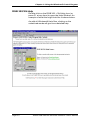
4. Installation of the software creates a Program Group
(Windows 3.1) or a Folder (Windows 95®) called
“Extron Electronics”. Icons for the Control Program
and the Help Program are installed in that group or
folder. The Window in the above illustration shows
an Extron Program Group.
5. Double-click on the RGB 302/304 Control Program
icon to start the program. You will be asked to select
the Comm Port. After selecting the Comm Port, the
software looks for the RGB 302/304, “reads” its
configuration, and then displays it in a window called
“Extron’s RGB 302/304 Interface Control Program”.
Normal Windows Control Panel
The following illustration shows an example of the
normal Windows control panel. Among the convenient
image adjusting features are controls for:
•
•
•
•
•
Vertical Shifting
Horizontal Shifting
Level adjustment
Peaking adjustment
Scan rate (display only)
Extron RGB 302/304 Universal Interface • User’s Manual
Page 4-2
Chapter 4 • Using the Windows® Control Program
RGB 302/304 Help
Double-click on the RGB 302 + 304 Help Icon (or
press F1 at any time) to open the Help Window. An
example of what this might look like is shown below.
As with all Windows® Help files, clicking on the
underlined words will give more detailed help.
Page 4-3
Extron RGB 302/304 Universal Interface • User’s Manual
RGB 302/304 Universal Digital Interface
User’s manual
A
Appendix A
Programmer’s Guide
Remote Control Port – RS-232
Host-to-RGB 302/304 Instructions
Command/Response Table
RGB 302/304-Initiated Messages
Extron RGB 302/304 Universal Interface • User’s Manual
Appendix A • Programmer’s Guide
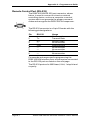
Remote Control Port (RS-232)
5
1
The RGB 302/304 RS-232 port connector, shown
below, is used to connect to a host or external
controlling device, such as a computer or control
system which can generate the proper command
codes and recognize the RGB 302/304 responses.
RS-232
9
6
The RS-232 connector is a 9-pin D female with the
following pin designations:
Pin
RS-232
Usage
1
2
3
4
5
6
7
8
9
—
Tx
Rx
—
Gnd
—
—
—
—
No connection
Transmit Data
Receive Data
No connection
Signal Ground
No connection
No connection
No connection
No connection
Commands and responses for programming the
RGB 302/304 Interface from a Host system connected
to the RS-232 port are listed on the next page.
The RS-232 protocol is 9600 baud, 8-bit, 1 stop bit and
no parity.
Page A-1
Extron RGB 302/304 Universal Interface • User’s Manual
Appendix A • Programmer’s Guide
Host-to-RGB 302/304 Instructions
The RGB 302/304 will recognize certain ASCII
characters as instructions. It then responds to those
characters with appropriate information.
Unrecognizable codes will result in an error code as
the response.
Examples of RGB 302/304 RS-232 connections are
shown here.
RGB 302
Control
System
LCD SYNC
SER REM
75 OHM
32
RS-2
MBC
CL
OG/E
T
ANAL
INPU
ER
POW
DIO
AU
R
V
T
TPU
OU
Hi Carol
IN
L
V
H/H
OUT
B
G
0.5A
40V
100-2
R
RS-232
Control Cable
Hz
50/60
Hi Carol
RGB 304
Control
System
LCD SYNC
SER REM
75 OHM
32
RS-2
DIO
AU
V
R
L
T
TPU
OU
V
H/H
OUT
B
Hi Carol
G
0.5A
40V
100-2
R
Hz
50/60
RS-232
Control Cable
Hi Carol
Command/Response Table
Definitions and Abbreviations:
↵ = CR/LF
(Hex values: 0D 0A)
= 1 thru 8 (steps of peaking)
= -127 ↔ 0 ↔ +127 (enhancement control range)
= Controller software version to 2nd decimal place
= xxx.xx (frequency in Hz or kHz)
= Menu language (1 = English, 2 = Spanish,
3 = French, 4 = German)
= Output sync format where 0 = Automatic*, 1 = Sync
on Green, 2 = Composite, 3 = H & V (normal), 4 = H &
V (both +), 5 = H & V (+H, -V), 6 = H & V (-H, +V),
and 7 = H & V (both -)
* If executing the I/i command (Request Information)
and sync output is set to Automatic (0), then 0 = RGB
with sync on Green, 8 = RGB with separate H & V,
and 9 = RGB with Composite sync.
= 0 or 1, 0 = Off, 1 = On
Extron RGB 302/304 Universal Interface • User’s Manual
Page A-2
Appendix A • Programmer’s Guide
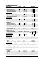
Simple Commands
Commands
ASCII
Video Level Control
specify video level
increment video level
decrement video level
{Y
}Y
Peaking Control
specify video peaking
increment video peaking
decrement video peaking
{_
{_
Horizontal Shift
specify horizontal shift
increment horizontal shift
decrement horizontal shift
{H
}H
Vertical Shift
specify vertical shift
increment vertical shift
decrement vertical shift
{/
}/
Hex
Response
↵
↵
↵
Y
+ 59
7B + 59
7D + 59
Brt
Brt
Brt
_
+ 5F
7B + 5F
7D + 5F
Pkg
Pkg
Pkg
↵
↵
↵
H
+ 48
7B + 48
7D + 48
Hph
Hph
Hph
↵
↵
↵
/
+ 2F
7B + F
7D + F
Vph
Vph
Vph
↵
↵
↵
Executive Mode (Front Panel Lockout)
Executive mode on
X
Executive mode off
x
58
78
Exe 1↵
Exe 0↵
Read DIP Switches
Read DIP switches
1B+70+30+30
Esc p 00 ↵
Ser
00 Dds
•Trm
•
↵
Write Sync Mode
`↵
+ 60
Syn
↵
Memory Cycling
Enable
Disable
.
,
2E
2C
Mem 1 ↵
Mem 0 ↵
Backlite Display Mode
Auto
On
S
s
53
73
Mut 1 ↵
Mut 0 ↵
1B+50+30+32
Updated ↵
Write ID Screen
Esc P 02 (up to 32 characters) ↵
Read ID Screen
Esc p 02 ↵
Menu Language
English
Spanish
French
German
Page A-3
#1
#2
#3
#4
1B+70+30+32
23 + 31
23 + 32
23 + 33
23 + 34
02 (up to 32 characters) ↵
Fnc 1 ↵
Fnc 2 ↵
Fnc 3 ↵
Fnc 4 ↵
Extron RGB 302/304 Universal Interface • User’s Manual
Appendix A • Programmer’s Guide
Commands
ASCII
Hex
Response
Set Fade To Black
Fade Screen
B
42
Blk 1 ↵
Clear Fade To Black
Fade Screen
b
62
Blk 0 ↵
Unit Reset
Reset Unit
Esc P 99 ↵
1B+50+39+39
Updated ↵
Q/q
51/71
QVER
N/n
4E/6E
Query Software Version
↵
Request Part Number
N60-243-01 ↵ (for RGB 302)
N60-244-01 ↵ (for RGB 304)
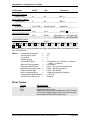
Request Information
Hph •Vph
•Vrt
↵
•Brt
I/i
•Pkg
•Syn
49/69
•Mem
•Exe
•Mut
•Blk
•Fnc
•Hrt
Example: Hph-112•Vph+009•Brt+000•Pkg1•Syn6•Mem1•Exe1•Mut0•Blk0•Fnc1•Hrt
031.47•Vrt059.94 ↵
Where:
Horizontal Shift (Hph)
Vertical Shift (Vph)
Level (Brt)
Peaking (Pkg)
Sync Mode (Syn)
=
=
=
=
=
Memory Cycling (Mem)
Executive Mode (Exe)
Backlite Automode (Mut)
Fade to Black (Blk)
Menu Language (Fnc)
Horizontal Scan Rate (Hrt)
Vertical Scan Rate (Vrt)
=
=
=
=
=
=
=
-112
+9
0
1
6 (Separate H & V with H = negative
and V = positive)
1 (Enabled)
1 (On – Front Panel Locked Out)
0 (Off – Backlite stays lit)
0 (Off – Not faded)
1 (Menu language is English)
31.47 kHz
59.94 Hz
Error Codes
Code
Description
E10
E13
E14
Invalid command
Invalid value (too large)
Illegal command for this configuration (DIP Switch 1
is set ON for Digital Display Sync Processing and
Horizontal/Vertical Shift is requested)
Extron RGB 302/304 Universal Interface • User’s Manual
Page A-4
Appendix A • Programmer’s Guide
RGB 302/304-Initiated Messages
When a local event takes place, such as a Front Panel
operation, the RGB 302/304 responds by sending a
message to the Host. These RGB 302/304-initiated
messages are listed below. As an example, the RGB
302 messages would be:
(C) COPYRIGHT 1998, EXTRON ELECTRONICS
RGB 302, VX.XX ↵
This message appears when AC power is first applied.
(X.XX is the software version number.)
Reconfig↵
↵
A change has been detected from the Front Panel, or
a change in scan rate frequency has been detected, or
an operation has occurred that requires a new
memory block to be written. No response is expected
from the host, but the host program, as an example,
may want to request new status (I or i command).
↵
Reset↵
↵ and Updated↵
These messages appear upon a System Reset from
the Front Panel.
Fnc
↵
The Menu language has been changed from the Front
Panel.
Exe
↵
The keyboard has been locked/unlocked from the
Front Panel.
Page A-5
Extron RGB 302/304 Universal Interface • User’s Manual
Appendix A • Programmer’s Guide
____
Extron RGB 302/304 Universal Interface • User’s Manual
Page A-6