1
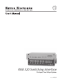
RGB 320 Switching Interface
Six Input, Two Output System
68-341-01
Printed in the USA
Precautions
Safety Instructions • English
This symbol is intended to alert the user of important operating and maintenance
(servicing) instructions in the literature provided with the equipment.
This symbol is intended to alert the user of the presence of uninsulated dangerous
voltage within the product's enclosure that may present a risk of electric shock.
Warning
Power sources • This equipment should be operated only from the power source indicated on the
product. This equipment is intended to be used with a main power system with a grounded
(neutral) conductor. The third (grounding) pin is a safety feature, do not attempt to bypass or
disable it.
Caution
Power disconnection • To remove power from the equipment safely, remove all power cords from
the rear of the equipment, or the desktop power module (if detachable), or from the power
source receptacle (wall plug).
Read Instructions • Read and understand all safety and operating instructions before using the
equipment.
Power cord protection • Power cords should be routed so that they are not likely to be stepped on or
pinched by items placed upon or against them.
Retain Instructions • The safety instructions should be kept for future reference.
Servicing • Refer all servicing to qualified service personnel. There are no user-serviceable parts
inside. To prevent the risk of shock, do not attempt to service this equipment yourself because
opening or removing covers may expose you to dangerous voltage or other hazards.
Follow Warnings • Follow all warnings and instructions marked on the equipment or in the user
information.
Avoid Attachments • Do not use tools or attachments that are not recommended by the equipment
manufacturer because they may be hazardous.
Slots and openings • If the equipment has slots or holes in the enclosure, these are provided to
prevent overheating of sensitive components inside. These openings must never be blocked by
other objects.
Lithium battery • There is a danger of explosion if battery is incorrectly replaced. Replace it only with
the same or equivalent type recommended by the manufacturer. Dispose of used batteries
according to the manufacturer's instructions.
Consignes de Sécurité • Français
Avertissement
Ce symbole sert à avertir l’utilisateur que la documentation fournie avec le matériel
contient des instructions importantes concernant l’exploitation et la maintenance
(réparation).
Alimentations• Ne faire fonctionner ce matériel qu’avec la source d’alimentation indiquée sur
l’appareil. Ce matériel doit être utilisé avec une alimentation principale comportant un fil de
terre (neutre). Le troisième contact (de mise à la terre) constitue un dispositif de sécurité :
n’essayez pas de la contourner ni de la désactiver.
Ce symbole sert à avertir l’utilisateur de la présence dans le boîtier de l’appareil de
tensions dangereuses non isolées posant des risques d’électrocution.
Déconnexion de l’alimentation• Pour mettre le matériel hors tension sans danger, déconnectez tous
les cordons d’alimentation de l’arrière de l’appareil ou du module d’alimentation de bureau (s’il
est amovible) ou encore de la prise secteur.
Attention
Lire les instructions• Prendre connaissance de toutes les consignes de sécurité et d’exploitation avant
d’utiliser le matériel.
Conserver les instructions• Ranger les consignes de sécurité afin de pouvoir les consulter à l’avenir.
Respecter les avertissements • Observer tous les avertissements et consignes marqués sur le matériel ou
présentés dans la documentation utilisateur.
Eviter les pièces de fixation • Ne pas utiliser de pièces de fixation ni d’outils non recommandés par le
fabricant du matériel car cela risquerait de poser certains dangers.
Protection du cordon d’alimentation • Acheminer les cordons d’alimentation de manière à ce que
personne ne risque de marcher dessus et à ce qu’ils ne soient pas écrasés ou pincés par des objets.
Réparation-maintenance • Faire exécuter toutes les interventions de réparation-maintenance par un
technicien qualifié. Aucun des éléments internes ne peut être réparé par l’utilisateur. Afin
d’éviter tout danger d’électrocution, l’utilisateur ne doit pas essayer de procéder lui-même à ces
opérations car l’ouverture ou le retrait des couvercles risquent de l’exposer à de hautes tensions
et autres dangers.
Fentes et orifices • Si le boîtier de l’appareil comporte des fentes ou des orifices, ceux-ci servent à
empêcher les composants internes sensibles de surchauffer. Ces ouvertures ne doivent jamais
être bloquées par des objets.
Lithium Batterie • Il a danger d'explosion s'll y a remplacment incorrect de la batterie. Remplacer
uniquement avec une batterie du meme type ou d'un ype equivalent recommande par le
constructeur. Mettre au reut les batteries usagees conformement aux instructions du fabricant.
Sicherheitsanleitungen • Deutsch
Vorsicht
Dieses Symbol soll dem Benutzer in der im Lieferumfang enthaltenen
Dokumentation besonders wichtige Hinweise zur Bedienung und Wartung
(Instandhaltung) geben.
Stromquellen • Dieses Gerät sollte nur über die auf dem Produkt angegebene Stromquelle betrieben
werden. Dieses Gerät wurde für eine Verwendung mit einer Hauptstromleitung mit einem
geerdeten (neutralen) Leiter konzipiert. Der dritte Kontakt ist für einen Erdanschluß, und stellt
eine Sicherheitsfunktion dar. Diese sollte nicht umgangen oder außer Betrieb gesetzt werden.
Dieses Symbol soll den Benutzer darauf aufmerksam machen, daß im Inneren des
Gehäuses dieses Produktes gefährliche Spannungen, die nicht isoliert sind und
die einen elektrischen Schock verursachen können, herrschen.
Stromunterbrechung • Um das Gerät auf sichere Weise vom Netz zu trennen, sollten Sie alle
Netzkabel aus der Rückseite des Gerätes, aus der externen Stomversorgung (falls dies möglich
ist) oder aus der Wandsteckdose ziehen.
Achtung
Lesen der Anleitungen • Bevor Sie das Gerät zum ersten Mal verwenden, sollten Sie alle Sicherheits-und
Bedienungsanleitungen genau durchlesen und verstehen.
Aufbewahren der Anleitungen • Die Hinweise zur elektrischen Sicherheit des Produktes sollten Sie
aufbewahren, damit Sie im Bedarfsfall darauf zurückgreifen können.
Befolgen der Warnhinweise • Befolgen Sie alle Warnhinweise und Anleitungen auf dem Gerät oder in
der Benutzerdokumentation.
Keine Zusatzgeräte • Verwenden Sie keine Werkzeuge oder Zusatzgeräte, die nicht ausdrücklich vom
Hersteller empfohlen wurden, da diese eine Gefahrenquelle darstellen können.
Instrucciones de seguridad • Español
Schutz des Netzkabels • Netzkabel sollten stets so verlegt werden, daß sie nicht im Weg liegen und
niemand darauf treten kann oder Objekte darauf- oder unmittelbar dagegengestellt werden
können.
Wartung • Alle Wartungsmaßnahmen sollten nur von qualifiziertem Servicepersonal durchgeführt
werden. Die internen Komponenten des Gerätes sind wartungsfrei. Zur Vermeidung eines
elektrischen Schocks versuchen Sie in keinem Fall, dieses Gerät selbst öffnen, da beim Entfernen
der Abdeckungen die Gefahr eines elektrischen Schlags und/oder andere Gefahren bestehen.
Schlitze und Öffnungen • Wenn das Gerät Schlitze oder Löcher im Gehäuse aufweist, dienen diese
zur Vermeidung einer Überhitzung der empfindlichen Teile im Inneren. Diese Öffnungen dürfen
niemals von anderen Objekten blockiert werden.
Litium-Batterie • Explosionsgefahr, falls die Batterie nicht richtig ersetzt wird. Ersetzen Sie
verbrauchte Batterien nur durch den gleichen oder einen vergleichbaren Batterietyp, der auch
vom Hersteller empfohlen wird. Entsorgen Sie verbrauchte Batterien bitte gemäß den
Herstelleranweisungen.
Advertencia
Este símbolo se utiliza para advertir al usuario sobre instrucciones importantes de
operación y mantenimiento (o cambio de partes) que se desean destacar en el
contenido de la documentación suministrada con los equipos.
Alimentación eléctrica • Este equipo debe conectarse únicamente a la fuente/tipo de alimentación
eléctrica indicada en el mismo. La alimentación eléctrica de este equipo debe provenir de un
sistema de distribución general con conductor neutro a tierra. La tercera pata (puesta a tierra) es
una medida de seguridad, no puentearia ni eliminaria.
Este símbolo se utiliza para advertir al usuario sobre la presencia de elementos con
voltaje peligroso sin protección aislante, que puedan encontrarse dentro de la caja
o alojamiento del producto, y que puedan representar riesgo de electrocución.
Desconexión de alimentación eléctrica • Para desconectar con seguridad la acometida de
alimentación eléctrica al equipo, desenchufar todos los cables de alimentación en el panel trasero
del equipo, o desenchufar el módulo de alimentación (si fuera independiente), o desenchufar el
cable del receptáculo de la pared.
Precaucion
Leer las instrucciones • Leer y analizar todas las instrucciones de operación y seguridad, antes de usar
el equipo.
Conservar las instrucciones • Conservar las instrucciones de seguridad para futura consulta.
Obedecer las advertencias • Todas las advertencias e instrucciones marcadas en el equipo o en la
documentación del usuario, deben ser obedecidas.
Evitar el uso de accesorios • No usar herramientas o accesorios que no sean especificamente
recomendados por el fabricante, ya que podrian implicar riesgos.
Protección del cables de alimentación • Los cables de alimentación eléctrica se deben instalar en
lugares donde no sean pisados ni apretados por objetos que se puedan apoyar sobre ellos.
Reparaciones/mantenimiento • Solicitar siempre los servicios técnicos de personal calificado. En el
interior no hay partes a las que el usuario deba acceder. Para evitar riesgo de electrocución, no
intentar personalmente la reparación/mantenimiento de este equipo, ya que al abrir o extraer las
tapas puede quedar expuesto a voltajes peligrosos u otros riesgos.
Ranuras y aberturas • Si el equipo posee ranuras o orificios en su caja/alojamiento, es para evitar el
sobrecalientamiento de componentes internos sensibles. Estas aberturas nunca se deben obstruir
con otros objetos.
Batería de litio • Existe riesgo de explosión si esta batería se coloca en la posición incorrecta. Cambiar
esta batería únicamente con el mismo tipo (o su equivalente) recomendado por el fabricante.
Desachar las baterías usadas siguiendo las instrucciones del fabricante.
Contents
Contents
Legend of Icons ................................................................................................................. ii
Revision Information .......................................................................................................... ii
Chapter One • Introduction to Switching Interface
What is a Switching Interface? .................................................................................................... 1-1
Function ......................................................................................................................... 1-1
Controlling the RGB 320 Interface .................................................................................. 1-2
Features ......................................................................................................................... 1-3
Specifications ................................................................................................................. 1-3
RGB 322, RGB 324, RGB 326 and RGB 340 Input Buffers ........................................................ 1-5
Chapter One • Illustrations
Figure 1-1. Example of an RGB 320 System Using Four Possible Buffer Types Installed in a Conference
Room ............................................................................................................................................................ 1-1
Figure 1-2. The RGB 322 and RGB 324 Can Be Installed in Walls. ............................................................. 1-2
Chapter Two • Rear Panel Connections
Connecting the RGB 320 Switching Interface ............................................................................. 2-1
Rear Panel Connectors .................................................................................................. 2-2
Audio Input Connections ................................................................................................ 2-3
Audio Output Connections ............................................................................................. 2-3
Choosing Cables for Remote Inputs ........................................................................................... 2-4
RGB 322/324/326/340 Input Buffer Connections ........................................................... 2-4
Composite Cables .......................................................................................................... 2-4
Buffer Input Cables ........................................................................................................ 2-5
Chapter Two • Illustrations
Figure 2-1. The RGB 320 as a Computer Video Switching Interface to a Line-quadrupling System ...........
Figure 2-2. The Rear Panel Has Connectors for Six Inputs and Two Outputs .............................................
Figure 2-3. Audio/Comm/Power Input Connectors with Captive Screws .....................................................
Figure 2-4. Examples of Round Audio Cable Connectors ...........................................................................
Figure 2-5a. Wiring the Input Audio Connectors Using RGB 324/326/340 Buffers ......................................
Figure 2-5b. Wiring the Input Audio Connectors Not Using RGB 324/326 Buffers ......................................
Figure 2-6a. Three Methods of Wiring Audio Output ....................................................................................
Figure 2-6b. Both Halves of the Output Connector Are Configured the Same ............................................
Figure 2-7. Installation Cables Connected to Inputs 1, 3 and 5 ...................................................................
Figure 2-8. One Installation Cable Can Be Used for Each Input and Each Output .....................................
Figure 2-9a. Installation Cable Wired for the RGB 320 ................................................................................
Figure 2-9b. Installation Cable Wired for the RGB 322/324/326/340 (RGB 322 Has No Audio) .................
2-1
2-2
2-3
2-3
2-3
2-3
2-3
2-3
2-4
2-4
2-5
2-5
Chapter Three • Operating the RGB 320 Panel
Controlling the RGB 320 Interface .............................................................................................. 3-1
Memory Functions (store/recall/clear) ............................................................................ 3-1
LCD Display ................................................................................................................... 3-1
Front Panel Controls ...................................................................................................... 3-2
Using the RGB 320 Front Panel Buttons ..................................................................................... 3-3
Making Input Adjustments from the RGB 320 Front Panel .......................................................... 3-4
Four Video and Audio Adjustments ................................................................................ 3-4
Diagnostic LEDs ............................................................................................................ 3-5
Rear Panel Switches ................................................................................................................... 3-5
Peaking Switch .............................................................................................................. 3-5
DIP Switches: Sync Options and Serration Pulses ......................................................... 3-5
Chapter Three • Illustrations
Figure 3-1. The RGB 320 Front Panel .......................................................................................................... 3-1
Figure 3-2. The Front Panel LCD Display ..................................................................................................... 3-2
Extron • User’s Manual • RGB 320 Switching Interface System
i
Contents
Figure 3-3. RGB 322/324/326/340 Differences ............................................................................................
Figure 3-4. RGB 320 Front Panel A/V Mode and Input Selection Buttons ...................................................
Figure 3-5. Select the A/V Mode by Pressing the Button on the RGB 320 Front Panel ..............................
Figure 3-6. Select the Desired Input by Pressing Its Button ........................................................................
Figure 3-7. Example of the Input Frequencies Being Displayed on the Default Screen ..............................
Figure 3-8. Turn the Appropriate Knob to Adjust an Input Function; the LCD Displays the Action ..............
Figure 3-9. The Appropriate Display Will Appear on the LCD Screen .........................................................
Figure 3-10. Six Diagnostic LEDs on the Front Panel ..................................................................................
Figure 3-11. Peaking Switch & DIP Switches Are Located in the Lower-right Section of the Rear Panel ...
3-2
3-3
3-3
3-3
3-4
3-4
3-4
3-5
3-5
Chapter Four • Using Windows® Control Program
Installing Windows Control Software ........................................................................................... 4-1
Normal Windows Control Panel ...................................................................................... 4-2
Executive Mode Panel .................................................................................................... 4-2
RGB 320 Help ................................................................................................................ 4-3
Chapter Four • Illustrations
Figure 4-1. Connect the PC to the RGB 320 Switching Interface ................................................................
Figure 4-2. Extron’s Program Group ............................................................................................................
Figure 4-3. Control Panel Functions .............................................................................................................
Figure 4-4. Executive Mode Uses a Limited Panel .......................................................................................
Figure 4-5. RGB 320 Help ............................................................................................................................
4-1
4-1
4-2
4-2
4-3
Appendix A • Programming the RGB 320
Remote Control Port (RS-232 and Contact Closure) .................................................................. A-1
Contact Closure Operation ............................................................................................. A-1
Host-to-RGB 320 Instructions ..................................................................................................... A-1
Command/Response Table ............................................................................................ A-2
RGB 320-Initiated Messages ......................................................................................... A-3
Appendix A • Illustrations
Figure A-1. The Serial Port Connector Wired for Both RS-232 and Contact Closure .................................. A-1
Figure A-2. Example of a Touch Panel Connected to the RS-232 Port ........................................................ A-1
Appendix B • Reference Material and Glossary of terms
Related Parts .............................................................................................................................. B-1
Glossary of Terms ....................................................................................................................... B-2
Index ........................................................................................................................................... B-7
Legend of Icons
The following icons may be used in this manual:
_________ Important information – an action or a step that must be done before proceeding.
_________ A Warning – possible dangerous voltage present.
_________ A Warning – possible damage could occur.
________ A Note, a Hint, or a Tip that may be helpful.
________ Additional information may be referenced in another section or document.
68-341-01 D
Printed in the USA
02 00
ii
RGB 320 Switching Interface System • User’s Manual • Extron
Contents
RGB 320 Switching Interface System
User’s Manual
1
Chapter One
Introduction to Switching Interface
What is a Switching Interface?
Extron • User’s Manual • RGB 320 Switching Interface System
Features
Specifications
Chapter 1 • Introduction to the RGB 320 Switching Interface System
What is a Switching Interface?
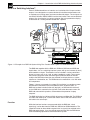
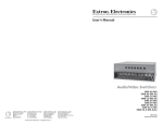
Extron’s RGB 320 combines an interface and a switcher with six inputs and two
outputs. It was designed as a system solution for installation environments such
as conference or training rooms and command/control centers. The six inputs can
use RGsB, RsGsBs, RGBS, RGBHV and line level audio. There are two buffered
outputs. One, for example, may go to a projector (the main presentation display)
and the other to a viewing monitor located near a podium.
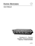
Figure 1-1. Example of an RGB 320 System Using Four Possible Buffer Types in a Conference Room
The RGB 320, together with the RGB 322, RGB 324, RGB 326 and RGB 340
input buffers, acts as a switching interface system, with up to six remote (or local)
buffer modules as inputs. These buffers can be installed in various convenient
places in a room, such as in a wall, or under a podium or a table. They transfer
the individual computer-video and audio signals (RGB 322 does not include
audio) to the RGB 320, where they are switched to a display device, a system
switcher or a line doubler, etc. The RGB 320 can be mounted in a rack with other
A/V components.
Figure 1-1 shows an example of a custom A/V installation in a conference room.
An RGB 320 is mounted in the rack outside the room. Inside the room, an
RGB 324 has been installed in the wall (top right), an RGB 326 in the left wall,
and an RGB 322 is mounted in the right wall, next to the document camera. An
RGB 340, mounted in the podium, accommodates the presenter’s laptop
computer.
The RGB 322 buffer has Horizontal Shift adjustment and Show Me. The RGB 326
has video and audio inputs, a termination switch and an LED that indicates when
this buffer is the active input.
Function
While the interface functions are processed within the RGB 320, “virtual
interfacing” can be done from the RGB 322, RGB 324 or RGB 340 buffers. The
“Show Me” button on these buffers requests that its signal(s) be switched to the
RGB 320 output device. It can also initiate communication with the RGB 320 to
allow the following adjustments to be made from the panel:
1-1
RGB 320 Switching Interface System • User’s Manual • Extron
Chapter 1 • Introduction to the RGB 320 Switching Interface System
•
•
•
•
horizontal shift (from RGB 322, RGB 324 & RGB 340)
vertical shift (from RGB 324 & RGB 340)
video level (from RGB 324 & RGB 340)
audio level (from RGB 324 & RGB 340)
The RGB 320 saves these adjustments in a memory associated with each input.
The RGB 320 has 15 memory blocks for each of the six inputs. The memory
blocks store the picture controls needed for an application or installation. When an
input buffer is selected, with a computer connected, the RGB 320 searches for a
match for that scan rate and automatically recalls the appropriate input settings
for that device. This eliminates having to recalibrate the settings each time a
specific computer is selected. Ten of the most popular computer scan rates are
permanently programmed into the RGB 320’s memory so programming may not
be necessary.
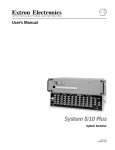
Figure 1-2. The RGB 322 and RGB 324 Can Be Installed in Walls
The RGB 320 has features that help to maintain the original signal integrity and
enhance overall system performance. A video level control is provided to
compensate for weak signal source or signal loss due to cables or other system
components. For example, if the signal from input #1 is weak, this control can
boost it; if the signal from input #3 is strong, it can be attenuated. Each setting is
stored for that input.
The RGB 320 also provides LCD sync processing that ensures a stable image for
LCD and DLP presentation devices.
Controlling the RGB 320 Interface
The RGB 320 can be controlled from front panel control buttons, from the
RGB 322, RGB 324 and RGB 340 buffers with “virtual interfacing” or with Extron’s
Windows® Control Program software. An RS-232 serial port allows control by a
third party control system. Extron’s software allows control of the RGB 320 from a
remote PC with a graphic interface.
The six inputs to the RGB 320 can originate from remote input buffers or from a
(local) device in the rack, such as another switcher, a line doubler, a dedicated
audio system or a computer interface. The RGB 322, 324, 326 or 340 input
buffers may be located in various places around a room. The RGB 320 switches
the signals to a display device, a system switcher or a line doubler, etc.
Extron • User’s Manual • RGB 320 Switching Interface System
1-2
Chapter 1 • Introduction to the RGB 320 Switching Interface System
Features
• High bandwidth – The RGB 320 provides a 220 MHz bandwidth for effective
transmission of high resolution computer video and audio signals.
• Central control– The RGB 320 interfaces and switches input sources from buffers
throughout the room to two displays for professional presentations.
• RS-232 control – Allows for third party control system (such as AMX® or
Crestron®) integration via the RS-232 serial port.
• Universal compatibility – The RGB 320 accepts RGsB, RsGsBs, RGBS and
RGBHV video signals, ensuring compatibility with all types of computer inputs.
• Rack mountable – The RGB 320 is housed in a 17 inch wide, 2U high metal
enclosure, with a 19-inch rack-mount face and mounting hardware.
• Digital Sync processing – Provides image stability for all CRT, LCD and DLP
projection devices.
• System diagnostics – Operations are monitored by LEDs on the front panel.
• Peaking – The RGB 320 has peaking control to maintain the original signal
integrity over long cable runs.
• Horizontal & vertical centering – This allows position (shift) control of the image.
• Audio gain & attenuation – Audio levels may be set for each input in increments of
1 dB, from -15 dB to +9 dB.
• Video levels – The RGB 320 provides adjustment for all RGB video levels via the
front panel buttons or remote PC with RS-232 control.
• Memory blocks – Ensures that each computer’s settings are saved, storing
horizontal & vertical centering, audio and video levels.
• Audio follow & breakaway – The RGB 320 allows audio to be switched with video
(follow) or switched separately from video (breakaway).
Specifications
Video input
Video throughput
Video outputs
Sync
1-3
Number/type
Connector
Nominal level(s)
Impedance
Horizontal frequency
Vertical frequency
Return loss
Routing
Gain
_
_
_
_
_
_
_
_
_
Bandwidth
Number/type/format
Connectors
Nominal level
Impedance
Return loss
Input type
Output type
_
_
_
_
_
_
_
_
Input level
Output level
Input impedance
Output impedance
_
_
_
_
6 analog RGBHV, RGBS, RGsB, RsGsBs
5 BNC female x 6
Analog — 0.3V to 1.45V p-p
75 ohms
15 kHz to 150 kHz (optimum 15 kHz to 62 kHz)
30 Hz to 170 Hz
-30 dB @ 5 MHz
6 X 1, 2 distributed outputs
0.5V to 1.45V p-p
Peaking — 0%, 50%, 100% (switch-selectable)
220 MHz (-3dB)
2 analog RGBHV, RGBS, RGsB
2 x 6 BNC female
0.5V to 1.45V p-p
75 ohms
-30 dB @ 5 MHz
Autodetect RGBHV, RGBS, RGsB, RsGsBs
RGBHV at all times, RGBS at all times,
RGsB switch-selectable
2.0V to 5.5V p-p with ±0.2VDC offset max.
4.0V to 5.0V p-p
10 kohms
75 ohms
RGB 320 Switching Interface System • User’s Manual • Extron
Chapter 1 • Introduction to the RGB 320 Switching Interface System
Sync
(continued)
Audio input
Max. propagation delay _
Max. rise/fall time _
Polarity _
Number/type _
Connectors _
Impedance _
Maximum level _
Input gain adjustment _
Audio throughput
Routing _
Gain _
Frequency response _
THD + Noise _
S/N _
Adjacent input crosstalk _
Stereo channel separation _
CMRR _
Audio output
Number/type _
Connectors _
Impedance _
Gain error _
Drive (HI-Z) _
Drive (600 ohm) _
Control/Remote —
Serial control port _
switching interface
Pin configurations _
Baud rate and protocol _
Contact closure _
Pin configurations _
Program control _
General
Power _
Temperature/humidity _
Rack mount _
Enclosure type _
Enclosure dimensions _
Shipping weight _
Vibration _
Approvals _
MTBF _
Warranty _
88 nS
3.2 nS
Positive, negative
6 stereo, balanced/unbalanced
6 3.5 mm captive screw terminal, 5 conductor
Balanced
25 kohms, DC coupled
Unbalanced 50 kohms, DC coupled
+19.5dBu, balanced or unbalanced
–15.0dB to +9.0dB, adjustable per input
6 X 1, 2 distributed outputs
Unbalanced 0dB, balanced +6dB
±0.05dB 20 Hz to 20 kHz
0.03% @1 kHz, 0.3% @ 20 kHz
+15dBu input, +21dBu output
Balanced input and output
>90dB, output 21dBu, balanced
>65dB @ 20 kHz, >80dB @1 kHz,
>80dB below 60 kHz
>80dB @1 kHz, >60dB @ 20 kHz
>75dB 20 Hz to 20 kHz
2 stereo (2 channel), balanced/unbalanced
2 3.5 mm captive screw terminals, 5 conductor
Unbalanced 50 ohms, balanced 100 ohms
±0.1dB channel to channel
>+21.0dBu, balanced at stated %THD+N
> +15.0dBu, balanced at stated %THD+N
RS-232 9-pin female D connector
2 = TX, 3 = RX, 5 = GND
9600, 8-bit, 1 stop bit, no parity
9-pin female D connector
1 = input 1, 4 = input 2, 5 = GND, 6 = input 3,
7 = input 4, 8 = input 5, 9 = input 6
Extron’s control program for Windows®
Extron’s Simple Instruction Set™ - SIS™
100VAC to 240VAC, 50/60 Hz, 20 Watts, internal,
auto-switchable
Storage -40° to +158°F (-40° to +70°C) / 10% to 90%
Operating +32° to +122°F (0° to +50°C) / 10% to 90%
Yes
Metal
3.50” H x 19.00” W* x 9.50” D
8.89 cm H x 48.26 cm W x 24.13 cm D
*includes attached rack ears
16 lbs (7.2 kg)
DIM weight 25
NSTA 1A in carton (National Safe Transit Association)
UL, CE, FCC Class A
30,000 hours
2 years parts and labor
Extron • User’s Manual • RGB 320 Switching Interface System
1-4
Chapter 1 • Introduction to the RGB 320 Switching Interface System
RGB 322, RGB 324, RGB 326 and RGB 340 Input Buffers
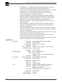
The RGB 322, 324 and 326 are each mounted on a two-gang wall plate that can
be installed in a wall, conference table, podium, etc., while the RGB 340 mounts
under a table or shelf. Each buffer has a 9-pin input connector compatible with
computers that output analog RGsB, RsGsBs, RGBS and RGBHV.
________ These buffer units have their own User’s Manual
(68-338-01).
A “Show Me” button on the RGB 322, RGB 324 and
RGB 340 buffer units allows the user to select their
buffer as the active source and present their output
onto the main display via the RGB 320. This is
called “virtual interfacing” control of the RGB 320.
Virtual interfacing also allows interface adjustments
to be made from certain buffer models. Thus, users
may interact with the main display directly from their buffer locations.
All buffers are available in gray, and the 2-gang wall plates are also available in
black or white face plates, so they can blend into walls, podiums, tables, etc.
Control can be via the RGB 320 front panel buttons, RS-232 control and Extron’s
control program for Windows®.
• Virtual interfacing– Allows you to make various video
and audio adjustments that are passed to the RGB
320, which then executes the adjustments and stores
them in memory.
• Show Me button– You can remotely select your own
buffer to become the active input source and, via the
RGB 320, display their information on the
presentation devices.
• Horizontal Shift (centering)– This adjusts the
horizontal position of the image on the video display.
• Remote connection– The buffers provide remote input connection for a
permanent A/V installation that requires more than one interface location.
• Universal compatibility– The buffers output analog
RGsB, RsGsBs, RGBS and RGBHV video signals,
ensuring compatibility with all types of analog
computer inputs.
The RGB 324 and RGB 340 have all of the features of
the RGB 322 as well as these:
• Show Me button– With the RGB 324 and RGB 340,
the Show Me button acts not only as the buffer’s
source selector, but also as the primary switch that
allows video and audio level adjustments to be made.
• Vertical shift (centering)– This allows vertical movement of the video image for a
centered presentation display.
• Video & audio level– The RGB 324 and RGB 340 allow you to make video and
audio level adjustments right from the buffer.
1-5
RGB 320 Switching Interface System • User’s Manual • Extron
Chapter 1 • Introduction to the RGB 320 Switching Interface System
RGB 320 Switching Interface System
User’s Manual
2
Chapter Two
Rear Panel Connections
Connecting the RGB 320 Switching Interface
Rear Panel Connectors
Choosing Cables
Composite Cables
Buffer Input Cables
Extron • User’s Manual • RGB 320 Switching Interface System
Installing RGB 320 Switching Interface Components • Chapter 2
Connecting the RGB 320 Switching Interface
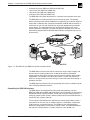
The RGB 320 has six inputs and two outputs, plus connections for RS-232
controls. Figure 2-1 shows an example of the types of equipment that may be part
of the interface system.
Each RGB 320 input has five BNC connectors to allow for RGsB, RGBS or
RGBHV input. There are also connectors for stereo audio. Although different
devices can be used as inputs to the RGB 320, it was designed to be the center
of a switching interface system, using buffer devices mounted in a wall, a table or
a podium. Extron makes three types of buffer units that provide remote input to
the RGB 320. In addition, the RGB 320 is a switcher, allowing one of six inputs to
be displayed through a projector or monitor.
The two buffered outputs are identical, with six BNC connectors and 2-channel
stereo audio. For example, one output may be used for the main display device (a
projector or data monitor), while the other may go to a rack or podium mounted
monitor. Switching and controls affect both output devices the same.
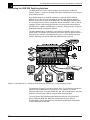
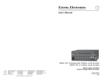
Figure 2-1. The RGB 320 as a Computer Video Switching Interface to a Line-quadrupling System
The example in Figure 2-1 includes a System 4LQex as the device that feeds the
projector, with the RGB 320 as its fourth input. This allows for six remote
computer video inputs, through the RGB 322, 324, 326 and 340 buffers, and three
System 4 inputs for other video input signals to be line-quadrupled.
The main focus of the procedures described here will be for using these input
buffers: RGB 322, RGB 324, RGB 326 and RGB 340. A User’s Manual
(P/N 68-338-01), which gives details on installation and operation of the buffers,
is also shipped with each buffer.
2-1
RGB 320 Switching Interface System • User’s Manual • Extron
Chapter 2 • Installing the RGB 320 Switching Interface Components
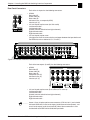
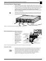
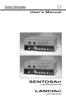
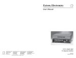
Rear Panel Connectors
Each of the six inputs has the following connectors:
• 5 BNCs
Red video (R)
Green video (G)
Blue video (B)
Horizontal sync, or composite (H/HV)
Vertical sync (V)
• 3.5 mm 10-pole captive screw (left 5 for audio)
Left channel audio +
Left channel audio –
Ground (common to both left and right channels)
Right channel audio +
Right channel audio –
• 3.5 mm 10-pole captive screw
(the right-most 5 are for communication and power between the input buffer and
the RGB 320, and are labeled A, B, C, D and E )
1
L
1 R
OUTPUTS
A
S
B
1
2
3
4
6
5
AUDIO
L
1 R
L
2 R
L
3 R
L
4 R
L
5 R
L
6 R
L
AR
L
REMOTE
BR
Figure 2-2. The Rear Panel Has Connectors for Six Inputs and Two Outputs
Each of the two outputs (A and B) has the following connectors:
• 6 BNCs
Red video (R)
Green video (G)
Blue video (B)
Composite sync (S)
Horizontal sync (H)
Vertical sync (V)
OUTPUTS
A
S
B
AUDIO
L
AR
L
RE
BR
• 3.5 mm 10-pole captive screw (5 for audio A, 5 for audio B)
Left channel audio +
Left channel audio –
Ground (common to both left and right channels)
Right channel audio +
Right channel audio –
_______ Seven 3.5 mm 10-pole captive screw connectors (P/N 10-319-11) are included
with each RGB 320. Six are for the inputs (audio/communications/power), and
one is for the output (audio A and audio B). One of these connectors is also
included with each RGB 322/324/326/340 input buffer.
Extron • User’s Manual • RGB 320 Switching Interface System
2-2
Installing RGB 320 Switching Interface Components • Chapter 2
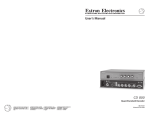
Audio Input Connections
The 10-pole receptacles are located on the rear panel below the BNC connectors.
Inputs are on the left side, and outputs are on the right. Each input receptacle has
five poles on its left labeled for left (L) and right (R) stereo, and the input number
is also labeled. Polarity (+/-) and ground are marked below. The right five poles
are labeled COM and PWR for use with an RGB 322/324/326/340 input buffer.
Input
2
L
Cable connectors are supplied with the RGB 320, one for each input and output.
The wires are secured using the captive screws inside the
Input
connectors. (See Figure 2-3.) Each connector is then
L
2 R
plugged into the appropriate input channel position on
the rear panel. If you are not using RGB 322/324/326/
340 input buffers, the right five poles are not used.
R
Figure 2-3. Audio/Comm/Power Input Connectors with Captive Screws
When making connections for the RGB 320 from existing audio cables, see
Figures 2-5a and 2.5b. The round audio connectors are shown with the top one
(tip and sleeve only) for unbalanced audio and the bottom one (tip, ring and
sleeve) for balanced audio. The “ring”, “tip” and “sleeve” markings are also used
on the captive screw audio connector diagrams in Figure 2-5a and 2-5b. These
examples can be used together as a guide for making audio cables.
Tip
Sleeve
Tip (+)
Ring (-)
Ring (-)
Sleeve
Figure 2-4. Examples of Round Audio Cable Connectors
Three methods of wiring the connectors for audio input are listed and shown here.
Only the first method is used with RGB 324/326/340 input buffers.
Balanced Input (high impedance)
Tip
Ring
Left
Gnd
Sleeve(s)
Tip
Balanced High Impedance (High Z) Stereo Tip, Ring (Left & Right stereo)
See Figure 2-8 for wiring RGB 324/326/340 buffers.
Right
Ring
Balanced Input (600 ohms)
other half of connector
Tip
600 ohm
Ring
Figure 2-5a. Wiring the Input Audio Connectors Using RGB 324/326/340 Buffer
Input
L
2
Ring
If you are not using RGB 324/326/340 for audio
inputs, any of the three methods can be used.
R
Left
Gnd
Sleeve(s)
Tip
Right
600 ohm
other half of connector
Balanced 600 ohm input Impedance Stereo Tip,
Ring (Left & Right)
Unbalanced High Impedance (High Z) Stereo Tip,
Ring, Ground (Left & Right)
Figure 2-5b. Wiring the Input Audio Connectors Not Using RGB 324/326/340 Buffer
Unbalanced Input (high impedance)
Tip
Sleeve
Left
Gnd
Tip
Sleeve
Right
other half of connector
Audio Output Connections
There are two audio outputs in one 10-pole connector. The left half is output A,
and the right half is output B. They can be wired in one of three ways.
Unbalanced Output (high impedance)
Outputs
Tip
Left
See warning.
Sleeve(s)
Gnd
Right
Tip
Balanced Output (high impedance)
Tip
Ring
Balanced Output (600 ohms)
Left
Gnd
Sleeve(s)
Tip
Right
Ring
See warning.
other half of connector
Tip
Ring
Sleeve(s)
Tip
Ring
Left
Gnd
Right
other half of connector
other half of connector
Figure 2-6a. Three Methods of Wiring Audio Output
Output
_________ If using the Unbalanced Output example in Figure 2-6a
(left-most example), connect the sleeve(s) to Ground
(Gnd). Connecting the sleeve(s) to a negative (-)
terminal will damage audio output circuits.
L
A
R
L
B
R
Figure 2-6b. Both Halves of the Output Connector Are Configured the Same
2-3
RGB 320 Switching Interface System • User’s Manual • Extron
Chapter 2 • Installing the RGB 320 Switching Interface Components
Choosing Cables for Remote Inputs
With the RGB 320 as the center of a computer video interface system, the input
connectors have specific functions, and the connectors must not be misused. The
ideal installation will use the RGB 322, RGB 324, RGB 326 or RGB 340 as inputs
through an installation (or composite) cable. Most of the examples used in this
manual will make this assumption. The User’s Manual for the RGB 322,
RGB 324, RGB 326, and RGB 340 gives detailed instructions for installing those
devices. (P/N 68-338-01)
_________ Regardless of which cables are used, their connectors must be wired the same
way on both ends. Any crossing of lines could damage the electronic circuits in
the buffer unit or in the RGB 320.
Inputs
Output(s)
Figure 2-7. Installation Cables Connected to Inputs 1, 3 and 5
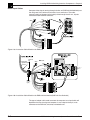
RGB 322/324/326/340 Input Buffer Connections
Figure 2-8 shows the
wiring for the audio,
communications
and power
connector for the
buffer. Note that the
wire and contact
assignments must
match those on the
RGB 320 end of the
cable shown in
Figures 2-9a and
2-9b.
No audio on
RGB 322
Shielded twisted pair
(braided shield separated)
White to L +
Black to L Shield to ground
Heat shrink over shield
Shield to ground
Shielded twisted pair
(braided shield separated)
Red to R +
Black to R Heat shrink over shield
Single, 20-gauge wires:
Brown to C
Violet to D
Gray to E
Shielded twisted pair
Black to A
Orange to B
(with braided shield trimmed)
Figure 2-8. One Installation Cable Can Be Used for Each Input and Each Output
Composite Cables
Composite cables, such as Extron’s Installation Cable, make installation easier,
because one jacketed cable can be dedicated to one input or to one output.
_______ Installation Cable includes a combination of several types of cables that are
enclosed in one jacket. The combination can carry video, audio, power,
communications, etc. If you will be making cables, follow the guidelines in
Appendix A of the RGB 322, 324,326 and 340 User’s Guide.
Extron • User’s Manual • RGB 320 Switching Interface System
2-4
Installing RGB 320 Switching Interface Components • Chapter 2
Buffer Input Cables
Computer video signals coming through a buffer unit (RGB 322/324/326/340) use
the red, green, blue, horizontal and vertical sync connectors. The audio,
communications and power (to the buffer) come through the 3.5 mm, 10-pole
connectors below the BNC connector.
Red
White
Green
Blue
Black
Yellow
Grn/Blk
White
Black
Shields
Red
Black
Black
Orange
Brown
Violet
Gray
Figure 2-9a. Installation Cable Wired for the RGB 320
Electrical
box
Mini Coax
White
Bend radius
approximately
3.5 inches
Blue
Green
Red
No audio on
RGB 322
twisted pair and would probably be neater. It
Black
Yellow
Clamp
(not too
tight)
Grn/Blk
White
Black
Shields
Red
Black
Black
Orange
Brown
Violet
Gray
Figure 2-9b. Installation Cable Wired for the RGB 322/324/326/340 (RGB 322 Has No Audio)
The type of adapter cable used to connect the computer to an input buffer will
depend on the brand and type of computer. It must adapt to the 9-pin, male
connector on the RGB 322, 324, 326, or 340 buffer unit.
2-5
RGB 320 Switching Interface System • User’s Manual • Extron
Chapter 2 • Installing the RGB 320 Switching Interface Components
RGB 320 Switching Interface System
User’s Manual
3
Chapter Three
Operating the RGB 320 Panels
Controlling the RGB 320 Interface
Input Buffer Control (RGB 322/324/326/340)
Using the RGB 320 Front Panel Buttons
Making Adjustments from the RGB 320 Front Panel
Rear Panel Switches
Extron • User’s Manual • RGB 320 Switching Interface System
Operating the RGB 320 Panels • Chapter 3
Controlling the RGB 320 Interface
The RGB 320 can be controlled from the front panel, from an input buffer, from an
external RS-232 device or from Extron’s Windows® based control software. This
includes selecting video, audio or both from one of six inputs, adjusting horizontal
and vertical centering or adjusting the video and audio levels. See Chapter 4 for
Windows® software and Appendix A for RS-232 programming.
Figure 3-1. The RGB 320 Front Panel
Memory Functions (store/recall/clear)
Although the interface functions are processed within the RGB 320, “virtual
interfacing” can be done from an RGB 322, RGB 324 or RGB 340 buffer by
pressing the “Show Me” button on its panel. The button requests that the
RGB 320 display the input signal from that buffer to the output display device(s),
and also initiates communication with the RGB 320 to allow adjustments to be
made from the buffer panel. These include horizontal shift, vertical shift, video
levels and audio levels. See the user’s manual 68-338-01 for details.
Adjustments for all inputs (buffers or other devices) can be made from the front
panel, or from an RS-232 host device. Regardless of where they were made,
these settings are saved in memory blocks associated with each input.
________ Memory blocks for each input can be cleared from the front panel by holding the
Video/Audio button while pressing the Input button for the channel to be reset.
The input LEDs blink and then are steady “on” when memory has been cleared.
When an input is selected, the RGB 320 searches for a configuration that
matches that computer, and it automatically recalls the appropriate video scan
rate. It may not be necessary to recalibrate the settings when a computer is
selected from an input. Ten of the most popular computer scan rates are
permanently programmed into the RGB 320’s memory.
LCD Display
The front panel LCD screen displays
five functions:
• The default display shows the scan rate
for the selected input (if no video is
connected to the selected input, both
frequencies will appear as 00.00)
• Horizontal shift (see page 3-4)
• Vertical shift (see page 3-4)
• Video level (see page 3-4)
• Audio level (see page 3-4)
Figure 3-2. The Front Panel LCD Display
________ When switching from one input to another, regardless of where it is from, the LCD
display blinks while “locking” in on the new input. For RS-232 programming, the
message “reconfig” will appear during this time. If adjustments are made during
this transition time, they may not be stored.
3-1
RGB 320 Switching Interface System • User’s Manual • Extron
Chapter 3 • Operating the RGB 320 Panels
Front Panel Controls
There are panel controls for adjusting four functions for the selected input. These
will be explained later in this chapter. Although the knobs can be turned endlessly
(no physical limit), the adjustment level will stop at its highest or lowest value.
Input buffer control (RGB 322/324/326/340)
Before going into the operation of the RGB 320 panel, here is an overview of the
input buffers that can be used with the RGB 320. Details on installing and
operating the buffer units are in the RGB 322/324/326/340 User’s Manual
(68-338-01). The buffer units’ features are summarized as follows:
Feature/Buffer model
Power LED
Video In
Audio In
75 Ohm/Hi Z
Horizontal shift adjust
Vertical shift adjust
Show me/Select button
Show me/Select light
Mount in wall/furniture
Mount under table/shelf
Available in three colors
Type
indicator
connector
connector
switch
control
control
control
indicator
design
design
design
322
yes
yes
no
yes
yes
no
yes
yes
yes
no
yes
324
yes
yes
yes
yes
yes
yes
yes
yes
yes
no
yes
326
yes
yes
yes
yes
no
no
no
no
yes
no
yes
340
yes
yes
yes
yes
yes
yes
yes
yes
no
yes
no
Figure 3-3. RGB 322/324/326/340 Differences
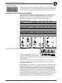
All buffers except the RGB 326 have some
control of the RGB 320, as initiated by the
“Show Me” button. Pressing this button initiates communication with the RGB 320
for the following:
• Request that the image from this buffer be displayed on the output device(s).
• The “Show Me” light on the buffer indicates when the input is selected, and it
blinks for audio breakaway.
• On the RGB 322, if “Show Me” is lit, use the H. Shift knob for horizontal centering.
• With either the RGB 324 or 340, if “Show Me” is lit, press the “Show Me” button
again and observe which of the four green LEDs is lit for the four adjustments:
H Shift, V. Shift, Video Level and Audio Level. Press the “Show Me” button until
the desired function is selected. Turn the “Adjust” knob to make the adjustment.
• The buffer’s power light shows “power on” and blinks when the RGB 320 is busy.
• Although the RGB 326 cannot request that its input be displayed, it has an active
light to show that it has been selected by the RGB 320 from another source.
• Adjustable horizontal and vertical shift (centering) for the selected input.
Extron • User’s Manual • RGB 320 Switching Interface System
3-2
Operating the RGB 320 Panels • Chapter 3
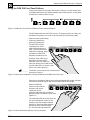
Using the RGB 320 Front Panel Buttons
Of the seven buttons on the front panel shown in Figure 3-4, the left-most button
(A/V Mode) determines what will be selected (audio, video or both), and the other
six buttons are used to select an input.
Figure 3-4. RGB 320 Front Panel A/V Mode and Input Selection Buttons
The A/V Mode button has two LEDs next to it. The top one (red) is for video and
the bottom one (green) is for audio. Press the button for one of three modes:
• Video and audio (audio follow)
• Video only (breakaway)
• Audio only (breakaway)
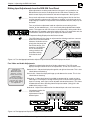
The two LEDs will light
according to the active
mode. Before selecting an
input, if you do not want the
mode that is indicated, press
the button until the LEDs
indicate the mode you want.
Example: If both LEDs are lit,
both video and audio will be
switched. If you want video only
from input #6, press the mode switch
until the video LED is lit and the audio
LED is unlit. (See Figure 3-5.)
________ This button is also used to clear memory blocks.
See note on Page 3-1.
Figure 3-5. Select the A/V Mode by Pressing the Button on the RGB 320 Front Panel
Press the input #6 button. Because you selected the video-only mode, the video
LED #6 (next to button #6) will light, but the audio LED #6 will not light.
When the RGB 320
switches to input #6, the
horizontal and vertical
frequencies for the
computer video from that input will be
displayed in the LCD default screen. (See
Figure 3-7.)
The audio input LED will remain lit for the
last input selected with audio. For this
example, input #3 had been selected
previously, and it had audio; therefore,
the input #3 audio LED will remain
on, as will the input #6 video LED.
Figure 3-6. Select the Desired Input by Pressing Its Button
3-3
RGB 320 Switching Interface System • User’s Manual • Extron
Chapter 3 • Operating the RGB 320 Panels
Making Input Adjustments from the RGB 320 Front Panel
When adjustments are being made from the front panel, an input buffer or an
RS-232 device, the results are displayed on the LCD screen. Otherwise, the
default screen displays the horizontal and vertical frequencies. See Figure 3-7.
________ Do not make adjustments immediately after switching inputs. Wait for the Horz
and Vert frequency values on the LCD panel to stabilize, or for the image on the
output display to stabilize. If adjustments are made before that time, they may not
be stored.
Turn any of the four adjustment knobs to adjust the current setting for that
function, for the selected input – if it is not currently being adjusted from another
source. This appears on the LCD screen as the adjustment is being made. When
the adjustment is complete, release the knob and, after a 7.5 second time-out, the
Tx LED blinks and the LCD once again displays the default screen.
Figure 3-7. Example of the Input Frequencies Being Displayed on the Default Screen
________ The LCD display will also show an adjustment that is being made from a remote
buffer unit or an RS-232 device.
However, the buffer unit has
priority over the panel and
the RS-232 device. (For
example, if an RGB 324
has V. Shift selected,
turning a knob on the
panel does nothing
until after the timeout.
Figure 3-8. Turn the Appropriate Knob to Adjust an Input Function; the LCD Displays the Action
Four Video and Audio Adjustments
Following is a description of each of the four adjustments. The LCD screen
displays the high and low limits for the adjustments, as well as the current value.
Adjustments
affect both of the
RGB 320 outputs;
therefore, for best
results, observe the
primary display
(projector), instead of
the secondary display
(a monitor in a rack or
podium), while making
the adjustment.
Horizontal shift – Moves the displayed image left and right on the screen. This is also
called Horizontal Centering.
Vertical shift – Moves the displayed image up and down on the screen. This is also
called Vertical Centering.
Video level – A video level control is provided to compensate for a weak or strong
video signal. For example, if the signal from input #1 is weak and the signal from
input #3 is strong, each signal can be adjusted and stored to memory. This allows
for better balance when switching from one input to another. (Unity gain is the
middle of the range, at 128.)
Audio level – Adjusts the audio level for the selected input and saves it to memory.
________ In breakaway mode, the
audio and video
adjustments will be for
different inputs.
Figure 3-9. The Appropriate Display Will Appear on the LCD Screen
Extron • User’s Manual • RGB 320 Switching Interface System
3-4
Operating the RGB 320 Panels • Chapter 3
Diagnostic LEDs
The front panel has six diagnostic LEDs. The right-most pair monitor +15 and -15
voltages, and the middle pair monitors +8 and -8 voltages. If any of these four
LEDs are not lit, the system will malfunction.
The left-most pair of LEDs will blink during
RS-232 communication with a controlling
device. Tx is transmit and Rx is receive.
________ Tx blinks each time a panel change has
been completed to notify the host of a
change in status.
Figure 3-10. Six Diagnostic LEDs on the Front Panel
Rear Panel Switches
Switches on the rear panel affect all the video signals that come from the
RGB 320.
Peaking Switch
To the left of the DIP switches is a three-position toggle switch. If the RGB 320 is
driving long cables, this switch allows
compensation for cable capacitance. The
middle position is Normal and does not alter
the output load. The lower position provides
50% peaking, and the upper position provides
100% peaking. Set the switch in the position
that provides the best image on the output
display device.
Figure 3-11. Peaking Switch and DIP Switches are Located in the Lower-right Section of the Rear Panel
DIP Switches: Sync Options and Serration Pulses
The DIP switches are located in the lower-right section of the rear panel. The
factory settings are all Off. Their functions are as follows:
1 LCD Select
Use the on position for an LCD output device or other digital device. In this
position, the horizontal and vertical shift (centering) controls are not active. Use
the off position for non-LCD or analog devices.
________ Because this switch disables the RGB 320 centering controls, when adjusting
centering from the projector, turn this switch on before adjusting the projector’s
centering controls.
2 Ser. Remove
Use the on position to remove serration pulses. In the off position, the RGB 320
will allow serration pulses, or it will add them if they are not already present.
3 V. Sync Pulse
In the on position, this switch increases the width of the vertical sync pulse to
approximately twice its original duration. The actual sync width will depend upon
the frequency of the incoming signal. Use the off position for normal width.
4 Neg. Sync
Use the on position for negative sync. This setting would depend upon the
requirements of the output display device (projector).
5 SOG
In the on position, sync on green is forced. Because the RGB 320 has three BNC
connectors for output sync, there is always one output with composite and two for
separate horizontal and vertical sync.
6 Spare
3-5
RGB 320 Switching Interface System • User’s Manual • Extron
Chapter 3 • Operating the RGB 320 Panels
RGB 320 Switching Interface System
User’s Manual
4
Chapter Four
Using Windows® Control Program
Installing Windows® Software Control
Normal Windows Control Panel
Executive Mode Panel
Extron • User’s Manual • RGB 320 Switching Interface System
RGB 320 Help
Using Windows® Control Software
Installing Windows® Control Software
This chapter is dedicated to using Extron’s “Windows Control Program for
RGB 320 via RS-232” software. Extron supplies this software that runs in the
Windows® operating system, version 3.1 or later. Communication between the
computer software and the RGB 320 is established after connecting the computer
to the RS-232 port on the rear panel of the RGB 320.
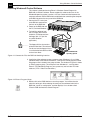
1. Connect the PC’s serial port
to the RS-232 connector on
the back of the RGB 320.
2. Power up the RGB 320 and
the PC, and load Windows.
3. To install the software from
the 3.5” floppy disk onto the
hard disk, run Setup.exe from
the floppy disk. (It’s just like
any other Windows
application.)
_______ The floppy disk has instructions
printed on the label. The software
can be run from the floppy drive, or
it can be loaded onto the hard drive
and run from there.
PC with Windows®
Operating System
Figure 4-1. Connect the PC to the RGB 320 Switching Interface
4. Installation of the software creates a program group (Windows 3.1) or a folder
(Windows 95®) called “Extron Electronics”. Icons for the control program and the
help program are installed in that group or folder. The window in Figure 4-2 shows
an Extron program group. This example is from Windows 3.1, and it includes
Extron’s VTG 200 Control Program; your system may not have the VTG 200
software. (VTG = Video Test Generator.)
Figure 4-2. Extron’s Program Group
5. Double-click on the RGB 320 icon to start the program. You will be asked to
select the serial port. After selecting the serial port, the software looks for the
RGB 320, “reads” its configuration, and then displays it in a window called
“Extron’s RGB 320 Interface Control Program”.
4-1
RGB 320 Switching Interface System • User’s Manual • Extron
Using Windows® Control Software
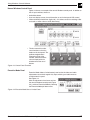
Normal Windows Control Panel
Figure 4-3 shows an example of the normal Windows control panel. In addition to
the six input switches, there are:
○ ○ ○
○ ○ ○
○ ○ ○
○ ○
○ ○ ○
○
○
○ ○
○ ○ ○
○ ○ ○
○
○
○
• The four controls have the
same functions as the four
knobs on the front panel. The
up/down nudge buttons
change the value of the
function, while the numeric
value is displayed in the
window next to the set of
buttons.
Figure 4-3. Control Panel Functions
○ ○
○ ○ ○
○
○
○ ○
• Audio Mute button
• Scan rate display screen (same information as on the front panel LCD screen)
• Video and Audio check boxes (right side) – this allows control for switching video
and audio, or either video or audio (breakaway).
Executive Mode Panel
Executive Mode allows a limited control panel so that the video and audio
adjustments cannot be changed. Only input switching and audio mute are
available from this panel.
See Figure 4-4.
After the adjustments have been set from
the normal Windows control panel (Figure
4-3), switch to Executive Mode by selecting
the Executive Mode pull-down menu.
Figure 4-4. Executive Mode Uses a Limited Panel
Extron • User’s Manual • RGB 320 Switching Interface System
4-2
Using Windows® Control Software
RGB 320 Help
Double-click on the Help icon (or press F1 at any time) to open the Help window.
Below is an example of what this might look like.
As with all Windows® help files, clicking on the underlined words will give more
detailed help.
Extron’s RGB 320 Control Program Help Contents
To learn how to use Help, press F1 or choose Using Help from the Help menu.
The RGB 320 Control program communicates with the Extron RGB 320
Switching Interface through the unit’s RS-232 port. (Defaults to 9600 baud, 8bit, 1 stop, no parity). It represents the same functions found on the unit’s frontpanel, but in an interactive graphical interface.
RGB 320 Main Screen (Normal mode):
RGB 320 Main Screen (Executive mode):
For Help on specific buttons and controls, click the appropriate item above.
Note that pressing F1 within the program will provide context-sensitive help.
Figure 4-5. RGB 320 Help
4-3
RGB 320 Switching Interface System • User’s Manual • Extron
Using Windows® Control Software
RGB 320 Switching Interface System
User’s Manual
A
Appendix A
Programming the RGB 320
Remote Control Port (RS-232 and Contact Closure)
Host-to-RGB 320 Instructions
Command/Response Table
RGB 320-Initiated Messages
Extron • User’s Manual • RGB 320 Switching Interface System
RS-232 Programming • Appendix A
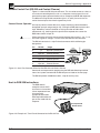
Remote Control Port (RS-232 and Contact Closure)
Figure A-1 shows the RS-232 port connector. This is used to connect to a host, or
to an external controlling device, such as a computer or control panel, that can
generate the proper command codes and can recognize the RGB 320 responses.
In addition to having RS-232 connections (pins 2, 3 and 5), there are also six
contact closure inputs that share the ground on pin #5.
Contact Closure Operation
A third party contact closure device can supply momentary contact between a
designated input pin and ground (pin #5), causing the RGB 320 to switch to that
input. Momentary contact is defined as having a duration of 250 to 500
milliseconds, e.g., touching pin #4 to pin #5 for the required time causes the
RGB 320 to switch to input #2.
_________ When connecting to RS-232, do not connect devices that use pins 1, 4, 6, 7, 8 or
9 for other signals or voltages. This will cause the RGB 320 to malfunction.
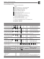
The RS-232 connector is a 9-pin D female connector with the following pin
designations:
Pin
1
2
3
4
5
6
7
8
9
RS-232
Input #1
Tx
Rx
Input #2
Gnd
Input #3
Input #4
Input #5
Input #6
Usage
Contact Closure
RS-232 Transmit Data
RS-232 Receive Data
Contact Closure
Signal Ground (both)
Contact Closure
Contact Closure
Contact Closure
Contact Closure
REMOTE
RS-232/CONTACT
Figure A-1. Serial Port Connector Wired for Both RS-232 and Contact Closure
Commands and responses for programming the RGB 320 Switching Interface
from a host system connected to the RS-232 port are listed on the next page.
The RS-232 protocol is 9600 baud, 8-bit, 1 stop bit and no parity.
Host-to-RGB 320 Instructions
The RGB 320 will
recognize certain ASCII
characters as instructions.
It then responds to those
characters with
appropriate information.
Unrecognizable codes will
get an error code with the
response.
Touch-panel with
RS-232 control
Figure A-2. Example of a Touch Panel Connected to the RS-232 Port
A-1
RGB 320 Switching Interface System • User’s Manual • Extron
Appendix A • RS-232 Programming
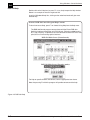
Command/Response Table
Definitions and abbreviations:
¿
= CR/LF
= input #1 through 6, or 0 = input disconnected
= 0 thru 255 (enhancement control range)
= xxx.xx (frequency in Hz or kHz)
= 0 thru 9 (10 steps of audio gain)
= numeric value -15 thru +09
= controller software version to 2nd decimal place
= 0 or 1, 0 = Off, 1 = On
= 15 thru 1 (15 steps of audio attenuation)
· = space (If indicated, the space must be there.)
Ah = this is a hexadecimal number
ph = phase: Hph - horiz shift; Vph - vert shift
rt = rate: Hrt - horiz frequency rate; Vrt - vert frequency rate
mt = mute: Amt - audio mute
brt= brightness - video level
Command from Host
Host Code
Resp
Examples
Description
ASCII HEX
to Host
Com. Response
Action/Explanation
Select input channel (aud & vid)
!
21h
C ¿
5!
C5¿
Select input channel #5(aud & vid)
h
Select input channel (audio only)
$
24h
A ¿
3$
A3¿
Select audio input channel #3
h
Select input channel (video only)
&
26h
V ¿
4&
V4¿
Select video input channel #4
h
Set hor. shift value (Hph) to
H
48
Hph
¿
39H
Hph039
¿
Set horizontal shift value to 39
h
h
Increment horizontal shift value
{H 7Bh48h
Hph ¿
{H
Hph040¿
Increase horizontal shift by 1
Decrement horizontal shift value
}H 7Dh48h Hph ¿
}H
Hph039¿
Decrease horizontal shift by 1
Set vert. shift value (Vph) to
/
2F
Vph
¿
57/
Vph057
¿
Set vertical shift value to 57
h
h
Increment vertical shift value
{/
7Bh2Fh Vph ¿
{/
Vph058¿
Increase vertical shift value by 1
Decrement vertical shift value
}/
7Dh2Fh Vph ¿
}/
Vph057¿
Decrease vertical shift value by 1
Note: A higher value moves the image downward, and a lower value moves it upward on the screen.
Set video level value (Brt) to
Y
59h
Brt ¿
32Y
Brt032¿
Set video level value to 32
h
Increment video level value
{Y
7Bh59h
Brt ¿
{Y
Brt033¿
Increase video level by 1
Decrement video level value
}Y 7Dh59h Brt ¿
}Y
Brt032¿
Decrease video level by 1
Audio un-mute
z
7A
Amt0¿
z
Amt0¿
Mute is off.
Audio mute
Z
5A
Amt1¿
Z
Amt1¿
Mute is on.
Set channel gain (Aud) to
G
47
Aud
¿
7G
Aud+07
¿
Set
audio value to +7 dB
h
h
Set audio channel attenuation
g
67
Aud
¿
1g
Aud-01
¿
Set
audio value to –1 dB
h
h
Increment audio level value
{G 7Bh47h
Aud ¿
{G
Aud+08¿
Increase audio level by 1
Decrement audio level value
}G 7Dh47h Aud ¿
}G
Aud+06¿
Decrease audio level by 1
Information request (Same as I)
i
69h
V ·A ·Amt ·Hph ·Vph ·Brt ·Aud ·Hrt ·Vrt ·Max6¿
Information request
I
49h
V ·A ·Amt ·Hph ·Vph ·Brt ·Aud ·Hrt ·Vrt ·Max6¿
Where: V=video channel; A=audio channel; Amt=aud mute; Hph = horiz shift; Vph=vert shift; Max=highest channel#
Response example: V2·A2·Amt0·Hph000·Vph255·Brt127·Aud+03·Hrt015.75·Vrt059.93·Max6
Request part number (Same as N) n
6Eh
N60-232-01¿
(60-232-01 = RGB 320)
Request part number
N
4Eh
N60-232-01¿
(60-232-01 = RGB 320)
Query software version (Same as Q) q
71h
QVER ¿ q
QVER1.23¿
(1.23 is example only)
Query software version
Q
51h
QVER ¿
Error Response
Invalid channel number
Invalid command
Invalid value
Busy
Code
E01¿
E10¿
E13¿
E16¿
Description
Input number requested could be greater than 6 (too large).
Command code not recognized.
Specified number could be out of range. (e.g., set video level to 256)
Adjustments are being made from an RGB 322/324/340 buffer.
Extron • User’s Manual • RGB 320 Switching Interface System
A-2
RS-232 Programming • Appendix A
RGB 320-Initiated Messages
When a local event takes place, such as a front panel operation, the RGB 320
responds by sending a message to the host. These RGB 320-initiated messages
are listed below.
(C) COPYRIGHT 1997, EXTRON ELECTRONICS RGB 320, VX.XX ¿
Power-on message:
The AC power has been applied. (x.xx is the software version number.)
RECONFIG¿
A change has been detected: from the front panel or from an RGB 322/324/340
buffer, a change in scan rate frequency has been detected, or an operation has
occurred that requires a new memory block to be written. No response is
expected from the host, but, for example, the host program may want to request
new status (I or i command).
Ci or Ai or Vi (where “i” is the input channel number)
The input has just been switched. A=audio; V=video; C = both audio & video.
________
A-3
RGB 320 Switching Interface System • User’s Manual • Extron
Appendix A • RS-232 Programming
RGB 320 Switching Interface System
User’s Manual
B
Appendix B
Reference Material
Related Product Lists
Glossary of Terms
Extron • User’s Manual • RGB 320 Switching Interface System
Reference and Glossary • Appendix B
Related Parts
Monitor Breakout Cables
MBC VGA/XGA HR
MBC Mac/Quadra
MBC SUN Sparc HR
26-162-01
26-018-02
26-424-01
Laptop Breakout Cables
LBC VGA HR 3’
LBC VGA HR 6’
LBC VGA HR 12’
LBC Mac HR 3’
LBC Mac HR 6’
LBC Mac HR 12’
LBC SUN HR 3’ (61 kHz)
LBC SUN HR 6’ (61 kHz)
LBC SUN HR 12’ (61 kHz)
LBC SUN HR 3’ (71 kHz)
LBC SUN HR 6’ (71 kHz)
LBC SUN HR 12’ (71 kHz)
LBC SUN HR 3’ (81 kHz)
LBC SUN HR 6’ (81 kHz)
LBC SUN HR 12’ (81 kHz)
LBC Mac/VGA 35 HR
26-224-02
26-224-01
26-224-03
26-363-03
26-363-01
26-363-04
26-413-04
26-413-01
26-413-05
26-413-06
26-413-02
26-413-07
26-413-08
26-413-03
26-413-09
26-394-01
Laptop Breakout Cables with Audio
LBC VGA HR 3’A
LBC VGA HR 6’A
LBC VGA HR 12’A
LBC Mac HR 3’A
LBC Mac HR 6’A
LBC Mac HR 12’A
LBC SUN HR 3’A (61 kHz)
LBC SUN HR 6’A (61 kHz)
LBC SUN HR 12’A (61 kHz)
LBC SUN HR 3’A (71 kHz)
LBC SUN HR 6’A (71 kHz)
LBC SUN HR 12’A (71 kHz)
LBC SUN HR 3’A (81 kHz)
LBC SUN HR 6’A (81 kHz)
LBC SUN HR 12’A (81 kHz)
26-441-01
26-441-02
26-441-03
26-442-01
26-442-02
26-442-03
26-443-01
26-443-02
26-443-03
26-444-01
26-444-02
26-444-03
26-445-01
26-445-02
26-445-03
Cable and Connectors
Hi-Res Installation Cable (500 ft.)
22-111-03
Hi-Res Installation Cable (1,000 ft.)
22-111-04
3.5 mm 10-pole captive screw connectors 10-319-11
BNC connectors for mini-high-res cables
100-074-51
Red heat shrink, for mini-hi-res cable (1 ft.) 39-010-03
Green heat shrink, for mini-hi-res cable(1 ft.) 39-011-03
Blue heat shrink, for mini-hi-res cable (1 ft.) 39-012-03
Yellow heat shrink, for mini-hi-res cable(1 ft.) 39-013-03
Black heat shrink, for mini-hi-res cable(1 ft.) 39-018-03
B-1
RGB 320 Switching Interface System • User’s Manual • Extron
Appendix B • Reference and Glossary
Glossary of Terms
For a complete glossary, see Extron’s web site (http://www.extron.com)
AC –
Alternating current. The flow of electrons that changes direction alternately.
AC reset –
The status that changes when power is removed from a device. Many electronic
devices have live power inside, even after “power off” has been initiated from a
panel or remote control device. This is not the same as “AC reset”, when power is
removed at the AC cord.
Amp –
Ampere. The international base unit of electric current. Symbolized by “A”. 1 amp
is equal to the steady current produced by 1 volt applied across a resistance of 1
ohm.
Analog –
A continuous action or movement that takes time to make a transition from one
level to another. Standard audio and video signals are analog. An analog signal
has an infinite number of levels between its highest and lowest value. (Changes
are not made by steps, such as with digital.)
ANSI –
American National Standards Institute. The organization that sets standards for
US A/V equipment.
ASCII –
American Standard Code for Information Interchange. The standard code
consisting of 7-bit coded characters (8 bits including parity check), utilized to
exchange information between data processing systems, data communication
systems and associated equipment. The ASCII set contains control characters
and graphic characters.
Attenuation –
To reduce the amplitude (strength) of a signal or current.
Audio follow –
A term used when an audio signal is tied to the video signal and they are switched
together; the opposite of breakaway.
Balanced audio –
Audio circuits that use three conductors for one audio signal: plus (+), minus (-)
and ground. The ground conductor is strictly for shielding, and does not carry any
signal. Also called differential audio.
Bandwidth –
A frequency range, or “band” of frequencies, between the limits defined by the
“half power points”, where the signal loss is -3dB. In audio and video, it is this
band of frequencies that can pass through a device without significant loss or
distortion. The wider the bandwidth, the better the quality that results, such as a
sharper picture, better sound, etc. The higher the bandwidth number, the better
the performance. (300 MHz is better than 250 MHz.) When a signal passes
through a path with more than one device (including cables), the limiting factor
(bottleneck) in that path is the device with the narrowest bandwidth.
Blooming –
Most noticeable at the edges of images on a CRT, “blooming” is when the light
hitting the screen is too intense and overdrives the phosphors. The edges of an
image seem to exceed its boundaries. Thin lines and sharp edges may look thick
and fuzzy. This may be caused by the brightness being set too high, or by a high
voltage problem.
BNC –
A cylindrical bayonet connector that operates with a twist-locking motion. Two
curved grooves in the collar of the male connector are aligned with two
projections on the outside of the female collar. This allows the connector to be
locked in place without tools.
Breakaway –
The ability to separate video and audio signals for the purpose of switching them
independently. For example, an audio and video signal from the same source
may be “broken away” and switched to different destinations. This is the opposite
of audio follow.
Buffer –
Generally referred to as a unity gain amplifier, a buffer is used to isolate the signal
source from the load. A buffer can be used for digital or analog signals. The
RGB 322, 324, 326 and 340 are input buffers to the RGB 320 switching interface.
Extron • User’s Manual • RGB 320 Switching Interface System
B-2
Reference and Glossary • Appendix B
Cable equalization –
The method of altering the frequency response of a video amplifier to compensate
for high frequency losses in cables that it feeds. See peaking.
Capacitance –
The storing of an electrical charge. Capacitance is a condition that exists between
conductors in a cable. At high frequencies, this represents an impedance called
capacitive reactance (Xc), which can cause signal loss or distortion.
Chroma –
The characteristics of color information, independent of luminance intensity. Hue
and saturation are qualities of chroma. Black, gray and white objects do not have
chroma characteristics.
Chrominance signal –
Part of a television signal containing the color information. Abbreviated as C.
Coaxial cable –
A two-conductor wire in which one conductor completely wraps the other
conductor, with the two separated by insulation. Constant impedance
transmission cable. Abbreviated as coax.
Component video –
Our color television system starts with three channels of information; red, green,
& blue (RGB). In the process of translating these channels to a single composite
video signal, they are often first converted to Y, R-Y, and B-Y. Both 3-channel
systems, RGB and Y, R -Y, B -Y, are component video signals. They are the
components that eventually make up the composite video signal. Higher quality
program production is possible if the elements are assembled in the component
domain.
Composite sync –
A signal combining horizontal and vertical sync pulses and equalizing pulses, with
no picture information and no signal reference level. Sometimes called C, S (as in
RGBS) or HV.
Composite video –
An all-in-one video signal comprised of the luminance (black and white),
chrominance (color), blanking pulses, sync pulses and color burst.
Contact closure –
A device that provides electrical contact between a designated input pin and
ground, causing a device, such as a switcher, to do a particular function.
Contrast –
The range of light and dark values in a picture, or the ratio between the maximum
and the minimum brightness values. Low contrast is shown mainly as shades of
gray, while high contrast is shown as blacks and whites with very little gray. It is
also a TV monitor adjustment that increases or decreases the level of contrast of
a displayed picture. Also called white level.
Crosstalk –
Interference between two audio or video signals, usually from an adjacent
channel, that adds an undesired signal to the desired signal. Crosstalk is caused
by magnetic/capacitative coupling or electrostatic induction, and can occur when
there are grounding problems or improper cable shielding. Video symptoms
include noise/ghosting, and audio symptoms include signal leakage.
Crosstalk isolation –
Attenuation of an undesired signal introduced by crosstalk.
D connector –
A connector with rounded corners and angled ends, taking on the shape of the
letter D. Commonly used in computers and video.
dB –
Decibel. The standard unit used to express gain or loss of power. It indicates the
logarithmic ratio of output power divided by input power. A power loss of 3 dB is
an attenuation of half of the original value. The term “3 dB down” is used to
describe the “half power point”.
DC –
Direct current. The flow of electrons in one direction.
Decibel –
See dB.
Decoder –
A device used to separate the RGBS (red, green, blue and sync) signals from a
composite video signal.
Differential audio –
See balanced audio.
B-3
RGB 320 Switching Interface System • User’s Manual • Extron
Appendix B • Reference and Glossary
Distribution amplifier –
DA. A device that allows connection of one input source to multiple, isolated
(buffered) output sources such as monitors or projectors.
FCC –
Federal Communications Commission. The US governmental agency that
controls and makes all policy for the use of broadcast airwaves.
Field –
One half of a standard television frame, containing every other line of information.
Each standard video frame contains two interlaced fields, sometimes referred to
as “field 1 and field 2”.
Flicker –
An alternating change of light intensity, typically perceived at a rate of a few hertz
to 60 Hz when viewing static images such as text. Flicker can occur when the
electron gun paints the screen too slowly, giving the phosphors on the screen
time to fade before they are refreshed.
Frame –
One complete picture in interlaced video. A video frame is made up of two fields,
or two sets of interlaced lines.
Frequency range –
The low-to-high limits of a device such as a computer, projector or monitor. See
bandwidth.
Gain –
A general term used to denote an increase in signal power or voltage produced
by an amplifier. The amount of gain is usually expressed in decibels above a
reference level. Opposite of attenuation.
Hertz –
Hz. The international term for cycles per second.
High impedance
Hi Z or High Z. In video, when the signal is not terminated it is said to have a Hi Z
load. Hi Z is typically 800-10k ohms or greater.
Horizontal rate –
Horizontal frequency. The number of complete horizontal lines (trace and retrace)
scanned per second. Typically measured in kHz.
Horizontal resolution –
The number of vertical lines that can be perceived in a video device.
Hue –
Tint control. The parameter of color that allows us to distinguish between colors.
Impedance –
W
Z. The opposition or “load” to a signal, measured in ohms and abbreviated or
Z. In video, typical low impedance circuits (low Z) are 600 ohms or less, and high
impedance circuits (high Z) may be 10k ohms or greater. Video termination
impedance is 75 ohm. Also see high impedance and low impedance.
Interlaced –
The process of scanning the picture onto a video screen whereby the lines of one
scanned field fall evenly between the lines of the preceding field.
IRE scale –
An oscilloscope scale that applies to composite video levels. Typically there are
140 IRE units in one volt (1 IRE = 7.14 mV).
K–
kilo. An abbreviation for 1,000. A kilobyte is 1,000 bytes. Because numbers used
in computer RAM sizes are in binary, the closest number is used. When talking
about memory size, etc., the numbers are rounded off (e.g., 1k byte is really
1,024 bytes.)
kHz –
Kilohertz. One thousand cycles per second.
LED –
Light-emitting diode. A low-power, long-life light source, usually red, green or
yellow in color. Some LEDs can produce two colors.
Level control –
The level control on some interface products is similar to the contrast control on a
data monitor. It can either increase or decrease the output signal level from the
interface to a data monitor or projector. This results in more or less contrast in the
picture.
Low impedance –
The condition where the source or load is at a lower impedance than the
characteristic impedance of the cable. Low source impedance is common; low
load impedance is usually a fault condition.
Extron • User’s Manual • RGB 320 Switching Interface System
B-4
Reference and Glossary • Appendix B
Luminance –
The photometric radiance of a light source. The signal that represents brightness
in a video picture. Luminance is any value between black and white. Luminance is
abbreviated as Y. Also see chrominance.
MHz –
Megahertz. One million cycles per second.
NTSC –
National Television Standards Committee. The television standard, for North
America and parts of South America, having 525 lines/60 Hz (60 Hz refresh). Two
fields per frame and 30 frames per second.
Output –
The product of an operation by a device going to some external destination, such
as another device, a video screen, image or hard copy.
PAL –
Phase Alternate Line. The phase of the color carrier is alternated from line to line.
It takes four full pictures for the color to horizontal phase relationship to return to
the reference point. This alternation helps cancel phase errors. For this reason,
the hue control is not needed on a PAL TV set. PAL, in many forms, is used in
Australia, England, Scandinavia, South Africa and Western Europe. PAL uses a
625-line, 50-field composite color transmission system.
Peak-to-peak –
p-p. The amplitude (voltage, for example) difference between the most positive
and the most negative excursions (peaks) of a signal.
Peaking –
A means of compensating for mid and high frequency RGB video bandwidth
response in data monitors and projectors, and for signal losses due to cable
capacitance. The higher the frequency and the greater the cable length, the more
peaking may be required.
Phantom power –
Power supplied to a microphone using the shield of a balanced audio connection.
Microphones using phantom power must be condenser style microphones
designed for use with phantom power systems. Damage can result to other types
of audio components from the improper use of phantom power.
Pin out –
An illustration or table that names signals, voltages, etc. that are on each pin of a
connector or cable.
Plenum cable –
Cable having a covering that meets the UL specifications for resistance to fire.
PLUGE –
Picture line up generation equipment. The name of a test pattern that assists in
properly setting picture black level. PLUGE can be part of many test patterns. The
phrase and origination of the test signal are both credited to the BBC.
Power (electrical) –
The dissipation of heat by passing a current through a resistance. Measured in
Watts (W), it is expressed by Ohm’s law from the three variables: Voltage (E) and
Current (I) and Resistance (R), i.e., P = I2xR, or, P = E2/R or P = ExI.
Resolution –
The density of lines or dots for a given area that make up an image. Resolution
determines the detail and quality in the image. A measure of the ability of a
camera or video system to reproduce detail. A measure of the amount of detail
that can be seen in an image. Often expressed as a number of pixels, but more
correctly it is the bandwidth. We say that a sharp, clear picture has high
resolution.
RGB –
Red, green, blue. The chrominance information in a video signal. The basic
components of the color television system. They are also the primary colors of
light in the additive color process.
RGB video –
A form of color video signal (red, green, blue) distinctly different from the
composite color video used in standard television sets. RGB can be displayed
only on an RGB monitor, which has a separate electron gun for each of these
primary colors. Some color television sets use only one gun. RGB monitors are
noted for their crisp, bright colors and high resolution.
B-5
RGB 320 Switching Interface System • User’s Manual • Extron
Appendix B • Reference and Glossary
RS-232 –
An Electronic Industries Association (EIA) serial digital interface standard
specifying the characteristics of the communication path between two devices
using D-type connectors. This standard is used for relatively short range
communications and does not specify balanced control lines. A serial control
standard with a set the number of conductors, data rate, word length and type of
connector to be used. Also specifies component connection standards with regard
to computer interface. Also called RS-232-C, which is the third version of the
RS-232 standard, which is functionally identical to the CCITT V.24 standard.
SECAM –
Sequential Couleur Avec Memoiré, translated as Sequential Color with Memory.
A composite color transmission system that potentially eliminates a need for both
a color and hue control on the monitor. One of the color difference signals is
transmitted on one line and the second is transmitted on the second line. Memory
is required to get both color difference signals for color decoding. SECAM is used
in France, Africa, Asia, Russia, Saudi Arabia and many Eastern European
countries. Similar to PAL, but it produces color signals in a different manner. 625
horizontal scan lines, 50 fields per second (625/50).
Serial port –
An input/output connection on the computer that allows it to communicate with
other devices in a serial fashion – data bits flowing on a single pair of wires. The
serial port is used with RS-232 protocol.
SMPTE –
Society of Motion Picture and Television Engineers. A global organization, based
in the United States, that sets standards for baseband visual communications.
This includes film as well as video standards.
SMPTE pattern –
The video test pattern consisting of color, black and white bands used as a
standard for setting up video equipment.
Software –
The programs used to instruct a processor and its peripheral equipment.
Switcher –
Term often used to describe a special effects generator, which allows the
operator to switch between video camera signals. Switchers are often used in
industrial applications to switch between video cameras monitoring certain areas
for display on a monitor or system of display devices.
Sync –
In video, a means of synchronizing signals with timing pulses to insure that each
step in a process occurs at exactly the right time. For example, horizontal sync
determines exactly when to begin each horizontal line (sweep) of the electron
beam. Vertical sync determines when to bring the electron beam to the top-left of
the screen to start a new field. There are many other types of sync in a video
system. (Also called sync signal or sync pulse.)
S-VHS –
Super-Video Home System. A high band video recording process for VHS that
increases the picture quality and resolution capability. See S-Video.
S-video –
The composite video signal is separated into the Luminance (Y; black and white)
and the Chrominance (C; color).
Terminal –
A device, typically having a keyboard and display, that is capable of sending text
to and receiving text from another device, a network, etc.
Termination –
A load, or impedance, at the end of a cable or signal line used to match the
impedance of the equipment that generated the signal. The impedance absorbs
signal energy to prevent signal reflections from going back toward the source. For
video signals, termination impedance is typically 75 ohms.
Vertical interval –
The synchronizing information that is presented between fields, and then signals
the picture monitor to return to the top of the screen to start another vertical scan.
Z–
A symbol for impedance.
Extron • User’s Manual • RGB 320 Switching Interface System
B-6
Reference and Glossary • Appendix B
Index
E
A
H
Adjustments
from front panel 3-4
warning (making too soon) 3-4
Attenuation
audio/video level 1-3
RS-232 programming A-2
defined B-2
Audio follow
feature 1-3
front panel indicators 3-3
defined B-2
Audio level
features 1-2, 1-5
from RS-232 control A-2
operation from buffer 3-1
operation from RGB 320 3-4
operation from software 4-2
H. shift
same as horizontal shift
Horizontal shift
from front panel 3-4
B
Boost
video level 1-2
Breakaway
feature 1-3
from front panel 3-3
from Windows software 4-2
from buffer panel 3-2
separate control 3-4
defined B-2
Buffers (inputRGB 322/324/326/340)
features 1-1, 1-5
overview 3-2
priority over RGB 320 panel 3-4
also see 68-338-01 user’s manual
C
Cables
choosing 2-4
also see 68-338-01 user’s manual
Communication
serial/RS-232 control 4-1
Contact closure
Remote control A-1
D
Diagnostic
panel LEDs 3-5
DLP display (projectors)
see LCD sync 3-5
B-7
Executive mode
Windows control panel 4-2
I
Installation cable
how to use 2-4
L
LCD display (front panel)
adjustment levels 3-4
scan rates 3-1
LCD display (projectors)
see LCD sync 3-5
LCD sync
rear panel switch 3-5
Line doubler/line quadrupler
used with RGB 320 2-1
M
Memory blocks
feature 1-2
function/description 3-1
clearing for input channel 3-1
Mode (audio/video)
see breakaway
N
Negative sync
rear panel switch 3-5
Normal Windows control panel
Windows software 4-2
P
Peaking
how to use rear panel switch 3-5
Program group
Windows 3.1 software 4-1
R
Remote control
Contact closure A-1
RS-232 A-1
RGB 320 help
Windows software 4-3
RGB 32/3404
features 1-5
RS-232
and control device A-1
and control priorities 3-4
and front panel LEDs 3-5
defined B-6
feature 1-3
serial comm port 4-1
S
Scan rate
stored for video input 1-2
Serration pulses
rear panel switch 3-5
Show Me
buffer feature 1-1, 1-5, 3-2
interacts with RGB 320 3-1
SOG
See sync on green
Sync
BNC connectors 2-2
defined B-6
feature - digital processing 1-3
Sync on green
rear panel switch 3-5
Sync options
rear panel switches 3-5
T
Termination
defined B-6
switch on buffers 1-2
V
V. shift
same as vertical shift
Vertical shift
front panel control 3-4
Vertical sync pulse
width control switch 3-5
Video level
feature 1-2
front panel control 3-4
Virtual interfacing
feature 1-2
from input buffer 1-5
W
Wall plate
buffer mounting 1-5
Windows
software control program 4-1
RGB 320 Switching Interface System • User’s Manual • Extron
FCC Class A Notice
Note: This equipment has been tested and found to comply with the limits for a Class A digital
device, pursuant to part 15 of the FCC Rules. These limits are designed to provide reasonable
protection against harmful interference when the equipment is operated in a commercial
environment. This equipment generates, uses and can radiate radio frequency energy and, if not
installed and used in accordance with the instruction manual, may cause harmful interference to
radio communications. Operation of this equipment in a residential area is likely to cause harmful
interference, in which case the user will be required to correct the interference at his own expense.
Note: This unit was tested with shielded cables on the peripheral devices. Shielded cables must be
used with the unit to ensure compliance.
Extron’s Warranty
Extron Electronics warrants this product against defects in materials and workmanship for a period
of two years from the date of purchase. In the event of malfunction during the warranty period
attributable directly to faulty workmanship and/or materials, Extron Electronics will, at its option,
repair or replace said products or components, to whatever extent it shall deem necessary to restore
said product to proper operating condition, provided that it is returned within the warranty period,
with proof of purchase and description of malfunction to:
USA, Canada, South
America, Central
America, and Asia:
Extron Electronics
1230 South Lewis Street
Anaheim, CA 92805, U.S.A.
Europe, Africa, and the
Middle East:
Extron Electronics, Europe
Beeldschermweg 6C
3821 AH Amersfoort
The Netherlands
This Limited Warranty does not apply if the fault has been caused by misuse, improper handling
care, electrical or mechanical abuse, abnormal operating conditions or non-Extron authorized
modification to the product.
If it has been determined that the product is defective, please call Extron and ask for an Applications
Engineer at (714) 491-1500 (USA), 31.33.453.4040 (Europe), or 65.226.0015 (Asia) to receive an RA# (Return
Authorization number). This will begin the repair process as quickly as possible.
Units must be returned insured, with shipping charges prepaid. If not insured, you assume the risk
of loss or damage during shipment. Returned units must include the serial number and a
description of the problem, as well as the name of the person to contact in case there are any
questions.
Extron Electronics makes no further warranties either expressed or implied with respect to the
product and its quality, performance, merchantability, or fitness for any particular use. In no event
will Extron Electronics be liable for direct, indirect, or consequential damages resulting from any
defect in this product even if Extron Electronics has been advised of such damage.
Please note that laws vary from state to state and country to country, and that some provisions of
this warranty may not apply to you.
EXTRON ELECTRONICS/RGB SYSTEMS, INC.
1230 South Lewis Street, Anaheim, CA 92805
800.633.9876 714.491.1500 FAX 714.491.1517
U.S.A.
EXTRON ELECTRONICS, EUROPE
Beeldschermweg 6C, 3821 AH Amersfoort
+31.33.453.4040 FAX +31.33.453.4050
The Netherlands
EXTRON ELECTRONICS, ASIA
41B Kreta Ayer Road, Singapore 089003
+65.226.0015 FAX +65.226.0019
Singapore
EXTRON ELECTRONIC INFORMATION
EXTRONWEB™: www.extron.com
EXTRONFAX™: 714.491.0192
24-hour access—worldwide!