1
RGB 203 Rxi • Setup Guide
These instructions provide a quick setup guide for the
Extron® RGB 203 Rxi interface. Installation and service must be
performed by authorized personnel only.
There are two RGB 203 Rxi models: one with EDID Minder® and one with
ADSP™. Unless otherwise stated, all instructions refer to both models.
Internal Configuration
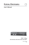
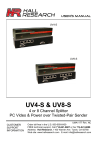
Step 1: Configure sync settings — Turn off all equipment and disconnect the
power sources. Remove the cover from the interface and locate jumper blocks J6,
J7, J20, and J11 (as shown at right).
CAUTION: Only authorized service personnel should perform changes to
internal jumpers. Take steps to prevent electrostatic discharge.
V Sync
H Sync
Enable
Sync
Set output sync to follow input sync: remove the jumper from J20.
3
2
1
Set vertical sync: for negative V sync, remove jumper from J7; for positive V sync, install jumper on J7.
Set horizontal sync: for negative H sync, remove jumper from J6; for positive H sync, install jumper on J6.
Clamp sync timing to back porch: place jumper between pins 1 and 2 on J11.
Clamp sync timing to sync tip: place jumper between pins 2 and 3 on J11.
Mounting
Step 2: Mount interface — Choose a suitable place to mount the interface (see the RGB 203 Rxi User Guide for details).
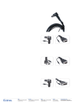
Rear Panel Connections
Both RGB 203 Rxi interfaces have identical rear panel connections. Connect, but do not power on, input and output devices.
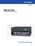
Step 3: Connect Video Inputs — Connect an RGBHV, RGBS, RGsB, or RsGsBs video input
to each 15-pin HD connector (a), as desired.
Step 4: Connect Audio Inputs — Connect an unbalanced stereo audio source to each
3.5 mm mini tip-ring-sleeve (TRS) stereo audio connector (b) for unbalanced audio input, as
desired. Wire the connector as shown in the figure at right.
NOTE: The interface accepts audio on inputs 1 and 2 only. When you select input 3, the
audio output is muted.
Step 5: Connect Local Monitor — If required, connect a monitor to this 15-pin HD connector (c).
Step 6: Connect Video Output — Connect the RGBHV, RGBS, or RGsB video display to the output
connectors (d) as shown in the figure at right.
Step 7: Connect Audio Output — Connect an audio device to this 3.5 mm, 5-pole captive screw
connector (e) for balanced or unbalanced audio output. For correct wiring, see the diagram below.
CAUTION: For unbalanced audio, connect
the sleeves to the center
contact ground.
DO NOT connect the sleeves
to the negative (-) contacts.
RGB 203 Rxi • Setup Guide (Continued)
Step 8: Connect RS-232 Controller — Connect an RS-232
controller to this DB9 connector (g) for remote control. For
correct wiring, see the diagram and table at right.
Pin
1
2
3
4
5
6
7,8,9
RS-232
Tx
Rx
Gnd
Contact Closure Function
Input #1
Input #1
Transmit data (-)
Receive data (+)
Input #2
Input #2
Gnd
Signal ground
Input #3
Input #3
Not used
Rear Panel DIP Switch Configuration
Step 9: Set Rear Panel DIP Switches — Configure the rear panel DIP switches (f) as shown in this table.
Switch
1 Up
Down
2 Up
Down
3 Up
Effect
DDSP™, no sync processing
ADSP™
RGsB output
RGBHV or RGBS output
Serration pulses
Switch
5 Up
Down
6 Up
Down
7 Up
Down No serration pulses
4 Up
Narrow V sync pulse
Down Wide V sync pulse
8
Effect
Monitor to input selection, Ground ID bits 4 and 11
Monitor tied to in #1, ID bits unterminated
Mono or left channel audio
Stereo audio
Autoswitch to highest input number with sync signal
present
Down Autoswitching off
Up
LCD backlight off
Down LCD backlight on
Step 10: Connect Power — Connect a standard IEC AC power connector (100-240 VAC, 50-60 Hz) to this socket (h).
NOTE: At this point, the ADSP model can be powered on and is ready for operation (see "Operation" on the back page
of this guide). For the EDID Minder model, see "Configuring EDID (EDID Minder Model Only)" below.
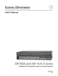
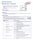
Front Panel Connections
LEVEL
RGB 203 Rxi WITH ADSP TM
CENTERING
PEAK
1
2
BOOST
3
CONTROL
INPUT
9
10
11
12
13
14
15
16
17
18
RGB 203 Rxi
LEVEL
PEAK
UNIVERSAL INTERFACE WITH EDID MINDER
CENTERING
50 Hz
EDID
SELECT
BOOST
CONTROL
1
2
RECORD
60 Hz
SPARE
3
INPUT
RGB 203 Rxi • Setup Guide (Continued)
Configuring EDID (EDID Minder Model Only)
The Extron EDID Minder ensures the resolution of the video source signals are compatible with the display devices. The
RGB 203 Rxi provides 14 factory-installed EDID values that can be used. By default, the EDID value is set to a resolution of
1024x768, which will allow most source devices to boot up and provide a signal that can be displayed. Alternatively, you can
record your own EDID information and use those values, or use EDID information from a monitor connected to the Local
Monitor output.
User-Recorded EDID
You may also record EDID information from a specific monitor as follows:
1. Connect a display to the Local Monitor output (c) and power on the monitor and interface.
2. Turn the EDID Select dial (o) to setting 0.
3. Press and release the recessed Record button (m). The LED light will flash red slowly three times while the EDID is
recorded and return to green when recording is complete.
NOTE: This EDID will be stored in memory until deleted or overwritten.
Using Recorded EDID Values
NOTE: To boot up correctly, the source device must be able to receive EDID information during the boot process.
Therefore, the interface (and the local monitor, if using pass-through EDID) must be switched on before the
source is switched on.
Use factory-installed EDID information or the user-recorded EDID as follows:
1. If you have not already done so, connect the RGB 203 Rxi to the source device. Do not switch on the source device at
this time.
2. Set the left front panel DIP switch (n) to the required frequency (50 or 60 Hz).
3. Set the rotary switch to the required value (see the table below). Settings 1 - E are factory installed. Setting 0 is for
user‑recorded and can only be used if a value has been stored at that location (see the previous section, "User-Recorded
EDID").
Rotary Switch
Position
Resolution
0
User-recorded EDID
1
800x600
2
1024x768 (default)
3
1280x720
4
1280x768
5
1280x800
6
1280x1024
7
1360x768
8
1366x768
9
1400x1050
A
1440x900
B
1600x1200
C
1680x1050
D
1920x1080
E
1920x1200
F
Local monitor pass-through
4. Power on the display device.
5. Power on the source device.
RGB 203 Rxi • Setup Guide (Continued)
Local Monitor Pass-through EDID
To use local monitor pass-through EDID:
1. If you have not already done so, connect the RGB 203 Rxi to the source device. Do not switch on the source device at
this time.
2. Set the rotary switch to position F.
3. If you have not already done so, connect a monitor to the Local Monitor output and power on that monitor and
interface.
4. Power on the remote display device.
5. Power on source device.
Operation
Level/boost (i) — Use this knob to alter picture brightness.
Peak (j) — Use this knob to alter picture sharpness.
Centering controls — Use these knobs to center the image on the screen vertically ({ k) or horizontally ([ l).
LCD display (p) — When the centering controls are being used, this display shows centering information. At other times it
shows scan rate.
Input selection (q) — This three-way switch selects among inputs. The corresponding LED (r) lights.
Troubleshooting
No response to { or [ centering controls:
•
DDSP is in use. Set DIP switch 1 on the rear panel to Off.
•
Front panel security lockout disables centering. Disable front panel security lockout (see RGB 203 Rxi User Guide).
No response to switching controls:
•
Front panel security lockout disables switching. Disable front panel security lockout (see RGB 203 Rxi User Guide).
If the image does not appear or is incorrectly displayed:
•
Ensure that all devices are plugged in and receiving power. The front panel LCD of the interface lights if the interface is
receiving power and an active sync signal. Check the cabling and the audio connector wiring and grounding, and make
adjustments as needed.
•
If using the model that has the EDID Minder, make sure the rotary dial and frequency DIP switch are set to the correct
values. If these settings are changed, reboot the source device.
•
If using the model that has the EDID Minder, make sure the video output device can support the resolution provided by
the EDID Minder. If necessary reset the rotary dial and reboot the source device.
NOTE: See the RGB 203 Rxi User Guide for a complete troubleshooting guide.
Extron USA - West
Extron USA - East
Extron Europe
Extron Asia
Extron Japan
Extron China
Extron Middle East
+800.633.9876
Inside USA/Canada
Only
+800.633.9876
Inside USA/Canada
Only
+800.3987.6673
Inside Europe Only
+800.7339.8766
Inside Asia Only
+81.3.3511.7655
+81.3.3511.7656 FAX
+400.883.1568
Inside China Only
+971.4.2991800
+971.4.2991880 FAX
+1.714.491.1500
+1.714.491.1517 FAX
+1.919.863.1794
+1.919.863.1797 FAX
+31.33.453.4040
+31.33.453.4050 FAX
+65.6383.4400
+65.6383.4664 FAX
Headquarters
© 2010 Extron Electronics. All rights reserved. www.extron.com
+86.21.3760.1568
+86.21.3760.1566 FAX
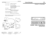
68-655-51
Rev A
11 10