1
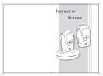
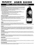
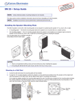
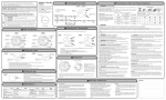
e NT: RTA.com for thtion O P IM tron talla w.ex uide, ins ations. o ww Go t te user g specific nd ple com ctions, a u instr SM 3 • Setup Guide This setup guide contains installation information about the Extron SM 3 speaker. Installing the Speaker Mounting Plate The SM 3 speaker comes with two types of speaker mounting plates: 0° mounting plate — The 0° plate allows the speaker to be mounted flat on a vertical wall with the speaker protruding less than four inches (ADA compliant) from the wall surface. 10° mounting plate — The 10° mounting plate allows the speaker to be installed at a 10 degree angle so that the speaker can be pointed down from an elevated position. The mounting plate can be installed vertically or horizontally as shown on the right. Catch Tab 0° Mounting Plate 10° Mounting Plate Vertical Mounting Horizontal Mounting NOTE: Observe all applicable building codes and local ordinances when installing the speaker. Mounting to a Wall Box 1. Route the speaker cable through the rear of the mounting plate and attach the wire ends to the quick connect contacts using a small screwdriver (see the following figures on the next page). Be sure to observe the correct polarity. NOTE: The positive (+) connector and the negative (-) connector are marked on the mounting plate. 2. Attach the mounting plate to the wall box, using two mounting screws (see figure below). NOTE: The mounting screw holes in the mounting plate allow for some degree of play and lateral movement so that the mounting screws may be aligned properly with the screw holes of the wall box. Observe U.S. and European screw locations, as shown on the right. Top Screw ATTENTION: Make sure that the wall box is secured to the wall structure and can handle the weight of the speaker. If there is doubt, secure the mounting plate with additional mounting screws. The wall stud mounting holes can be used for this purpose. European Box Screw Location U.S. Box Screw Location 1 SM 3 • Setup Guide (Continued) ATTENTION: Use the appropriate mounting screws. The screw heads must not protrude more than .074” (1.9 mm) above the screw holes in the mounting plate (see the figure below left). If the screw head protrudes too far above the mounting plate surface, damage to the speaker may occur when the speaker is attached (see the figure below right). 0.074” (1.9 mm) Good Quick Connect Contacts Bad 1.97” (5 mm) Mounting Screws Mounting to a Wall Stud 1. Install the speaker cables into the wall or conduit before installing the speaker mounting plate. Leave enough slack. 2. Locate the wall stud where the mounting plate will be installed and while positioning the mounting plate on the wall mark the location of two pilot holes using the holes on either side of the mounting plate so that the stud does not interfere with the speaker wire routing, as shown below. NOTE: A speaker wire access hole (see the figures below) must also be cut in the wall, so mark that hole location now with the mounting plate positioned on the wall while ensuring that the wall stud does not interfere with the wire routing and that the mounting plate hides the access hole. OR 0° Mounting Plate 10° Mounting Plate Alternate Access Point Alternate Access Points NOTE: When mounting to surfaces that do not allow Mounting Screws ATTENTION: 2 wires to be routed from behind (such as on masonry or concrete walls) and the wires are routed to the speakers via a raceway, use the alternate access points to run the wires to the quick connect speaker contacts (see the figures above). Use the appropriate mounting screws (see the above ATTENTION). 3. Drill the mounting plate pilot holes and cut the speaker wire access hole, as previously marked. 4. Route the speaker cable through the rear of the mounting plate and attach the wire ends to the quick connect contacts using a small screwdriver (see the illustrations at the top of this page). Besure to observe the correct polarity. 5. Attach the mounting plate to the wall. Attaching the Speaker to the Mounting Plate ATTENTION: By default, the SM 3 speaker is shipped unlocked. When mounting the speaker to the mounting plate, be sure that the speaker is unlocked. Failure to place the speaker in the unlocked position will result in damage to the speaker lock mechanism should an attempt be made to mount a locked speaker (see “Using the Security Key to Lock and Unlock the Speaker” below). NOTE: If a secondary attachment point is being used, see the “Attaching a Secondary Support Cable” section on the next page for installation details before proceeding further. Position the rear mounting slot of the speaker above the catch tab of the mounting plate, then slide the speaker down into the mounting plate so that the speaker is secured in place (see figure on the right). When properly seated, the speaker connections are automatically made. Using the Security Key to Lock and Unlock the Speaker Insert the key into the center of the speaker grill and turn the key, as needed, so that the speaker is in the unlocked position (see the figure below). There are three small raised “dimples” on the grill surface that surrounds the keyhole. Repeat this procedure, but set the key to the locked position to lock the speaker. Catch Tab Unlocked Twist to Lock/Unlock Unlocked Locked Removing the Speaker from the Mounting Plate To remove the speaker from the mounting plate, you must unlatch the locking mechanism. 1. Insert the security key into the keyhole of the speaker grill (see the previous section) and turn the key to the unlock position. 2. Remove the security key. 3. Apply pressure with your finger over the keyhole to unlatch the speaker from the mounting plate while lifting up on the speaker (see figure on the right). Press to Release ATTENTION: To avoid damaging or scratching the grill finish, do not use tools or sharp instruments to depress the unlocking mechanism hidden behind the center of the grill. 3 Attaching a Secondary Support Cable If a secondary support cable is being attached, use the included screw to attach a suitable cable to the screw hole, as shown below. Anchor this end to a suitable secure point. Attach cable here and secure. Insert screw here. Secondary Support Cable Reference only Extron Headquarters +800.633.9876 Inside USA/Canada Only Extron USA - West +1.714.491.1500 +1.714.491.1517 FAX 4 Extron USA - East +1.919.850.1000 +1.919.850.1001 FAX Extron Europe +800.3987.6673 Inside Europe Only Extron Asia +800.7339.8766 Inside Asia Only +31.33.453.4040 +31.33.453.4050 FAX +65.6383.4400 +65.6383.4664 FAX Extron Japan +81.3.3511.7655 +81.3.3511.7656 FAX Extron China +4000.EXTRON +4000.398766 Inside China Only Extron Middle East +971.4.2991800 +971.4.2991880 FAX +86.21.3760.1568 +86.21.3760.1566 FAX © 2013 Extron Electronics All rights reserved. www.extron.com Extron Korea +82.2.3444.1571 +82.2.3444.1575 FAX Extron India 1800.3070.3777 Inside India Only +91-80-3055.3777 +91 80 3055 3737 FAX 68-1540-50 Rev. B 04 13