1
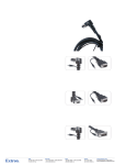
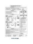
Operation and Specifications
Compatibility
The INERTIA is a multi-scanning device that accepts inputs in the 31 - 71 kHz frequency range.
The INPUT FORMAT LEDs are a general indication of the input signal frequency range.
Input LED
Computer
Resolution
Horiz.
Vert.
❍❍❍●
VGA 2
640 x 400
31.5 kHz 70 Hz
❍❍●❍
VGA 3 (pass thru)
640 x 480
31.5
60
❍❍●●
VESA 1
800 x 600
35.0
56
●❍❍❍
VESA 2
640 x 480
37.9
72
❍●●●
VESA 3
1024 x 768
48.4
60
❍●❍❍
VESA 5
800 x 600
37.9
60
●❍❍●
VESA 6
800 x 600
48.1
72
❍●❍●
MAC 13" / 14" display
640 x 480
35.0
67
●❍●❍
MAC 16" display
832 x 624
49.7
75
●●●❍
MAC 19" display
1024 x 768
60.2
75
●●●●
MAC 21" display
1152 x 870
68.7
75
❍●●❍
IBM 8514/XGA
1024 x 768
35.5
87
●❍●●
SUN
1152 x 900
61.8
66
●●❍●
SUN
1152 x 900
71.7
76
❍●●●
SGI
1024 x 768
48.0
60
❍❍❍✵
SGI
1280 x 1024
63.9
60
❍ = Off; ● = On; ✵ = Blinking LED. LEDs sequencing = input range exceeded,
LEDs all off = no signal, improper connection, etc.
User's Guide
Specifications
Input Signals
Computer Compatibility: SUN, SGI, PowerPC, Super VGA, Radius, Quadra, MAC
SERIES, Super MAC, and E-Machine graphics from 31 to 71 kHz (multi-scanning).
Video ....... 0.7 - 1.0 volts p-p
Sync ....... Composite sync (±), Sync on Green (±),
....... Horizontal and Vertical (±)
Input freq. compatibility ....... 31-71 kHz (multi-scanning)
Maximum Resolution ....... 1280 x 1024
Output Signals
Video ....... BNC - RGBS, 15-pin HD = VGA or SVGA
Sync ....... BNC = Composite sync
....... 15-pin HD = Composite or separate H&V
Output frequency ....... 31.5 kHz VGA or 35 kHz SVGA (Switchable)
Output resolution ....... 640 x 480 VGA or 800 x 600 SVGA (Switchable)
RGB video bandwidth ....... 120 MHz (-3 db)
Power Supply ....... 100-240 VAC, 50/60 Hz external auto-switchable
Dimensions ....... 10"W x 11.5"D x 1.5"H (25 W x 29 D x 3.8 H cm)
Shipping Weight ....... 9 lbs. (4 kg)
Warranty ....... Two years parts/labor
Supplied Cables and Adapters
VGA Input Cable, 6' (1.8m) ............................. Part Number 26-112-15
13W3/VGA return cable, 1' (0.3 m) ................. Part Number 26-371-01
13W3/VGA adapter .......................................... Part Number 26-372-01
MAC HV/VGA return cable, 1' (0.3 m) ............. Part Number 26-340-02
MAC HV/VGA adapter ...................................... Part Number 26-374-01
SM
EXTRON ELECTRONICS, EUROPE
Beeldschermweg 6C
3821 AH Amersfoort
+31-33-453-4040 FAX +31-33-453-4050
The Netherlands
EXTRON ELECTRONICS, ASIA
41B Kreta Ayer Road
Singapore 089003
+65-226-0015 FAX +65-226-0019
Singapore
INERTIA
CAD Workstation
to VGA Graphics
Trans-Converter
P/N 60-161-01
Page 3
EXTRON ELECTRONICS
1230 S. Lewis Street
Anaheim, CA 92805
(714) 491-1500 FAX (714) 491-1517
U.S.A.
CENTERING
79-07
68-339-01
Rev. A
Installation & Operation
Installation & Operation
Inertia installation and Operation
The INERTIA Graphics Trans-Converter allows high resolution SUN, SGI, Power PC,
Super VGA, Radius, Quadra, MAC series, Super MAC and E-Machine computervideo to be displayed on VGA and Super VGA devices by converting the signals to
either 640 x 480 or 800 x 600 resolution.
• Because the INERTIA has two buffered outputs, it can simultaneously drive LCD
products and any VGA compatible video display, such as: light-valve projector,
computer monitor, VGA/MAC-only large screen data projector, LCD panel, and
even a VGA/MAC color printer.
•
A front panel switch enables selection of either VGA 31.5 kHz (640 x 480) or
Super VGA 35 kHz (800 x 600). With VGA or SVGA selected, both of the
INERTIA’s outputs (RGBS on BNCs and VGA on 15-pin HD) are active, so two
simultaneous displays may be connected.
•
A third output (labeled Monitor Output) is provided so that the computer’s local
monitor can display the original computer-video signal and resolution.
Installation
1. Turn the computer and monitor power OFF.
2. Connect the computer/workstation video output to the INERTIA Computer Input
connector (Item I, Page 2) using the supplied cable and adapter if necessary
(see Supplied Cables and Adapters on Page 3).
3. Connect the CPU local monitor to the INERTIA Monitor Output connector (Item G,
Page 2) using the supplied monitor adapter cable (see Supplied Cables and
Adapters on Page 3) as shown in the diagram below.
4. Connect the presentation display(s) using either the RGBS output (Item L, Page
2) or the 15-pin HD output (Item N, Page 2) — or both.
5. Connect the INERTIA’s external power supply to the rear panel Power connector
(Item O, Page 2).
6. Turn on the computer and monitor and select the desired output signal using the
output format switch (Item D, Page 2).
Page 1
Extron • INERTIA • User’s Guide
Front Panel
A. FREEZE Frame Switch – Press the FREEZE switch button, the LED lights
and the INERTIA will store and output the current frame of video until the
FREEZE switch button is pressed again.
B. Power LED – Indicates power is being received from the 115/230 volt
power supply.
C. Input Format LEDs – Four LEDs indicate the frequency/resolution being
converted to VGA or Super VGA. Refer to Compatibility (Page 3) for key
to the LED format.
D. Output Format Switch – This switch affects both outputs 1 and 2 and
causes the output resolution to change to either VGA (31.5 kHz, 640 x 480)
or Super VGA (35 kHz, 800 x 600). Output resolution indicated by LEDs.
E. Zoom Switch – The Zoom switch makes either the top or bottom portion of
the displayed image to be enlarged for easier viewing of text on a largescreen display.
F. Horizontal ( ) and Vertical ( ) Centering – These controls may be
used to move the displayed image side to side, or up and down on the
screen.
Rear Panel
G. Monitor Output – This 15-pin HD female connector provides output for the
computer's local monitor – at its original resolution. Adapter cables are
supplied for conversion to 15-pin D (MAC/Quadra) or 13W3 (Sun/SGI) style
connectors.
Ω switch – IN for 75Ω termination when not using a local
H. HIGH Z / 75Ω
monitor. Out when using the computer's own monitor (Local monitor
supplies the termination).
I. Computer Input – The computer's video output connects to this 15-pin HD
male connector. Adapter cables are supplied for 15-pin D (MAC/Quadra) or
13W3 (Sun/SGI) style connectors.
J. H/V / SOG switch – Set the H/V / SOG switch to the H/V position for
computer signals with separate horizontal and vertical or composite sync. In
some isolated cases, setting the switch to SOG is necessary for computers
with sync on green, such as SGI.
Ω switch – This toggle switch is for input sync termination.
K. HI Z / 75Ω
L. Output 1 BNC connectors – RGB and composite sync BNC connectors
M. H/V / S switch – Output 2 sync switch - The VGA (15-pin HD) output can be
configured for composite (S) or separate H & V sync (H/V). VGA
compatible displays require this switch to be set in the H/V position.
N. VGA/SVGA - Output 2 connector- VGA or Super VGA output 15 -pin HD
connector
O. Power input connector - Connector for cable from external power supply
Extron • INERTIA • User’s Guide
Page 2