1
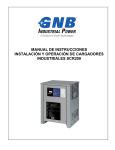
DEC200 SERIES
INDUSTRIAL BATTERY
CHARGER I&O MANUAL
TABLE OF CONTENTS
TITLE
1.
Important Operating Instructions
2.
Introduction
3.
Receiving Instructions
4.
Location and Installation of Charger
5.
Stacking
6.
AC Electrical Supply
6.1
Branch Circuit Protection
6.2
AC Voltage Connections
6.3
Ground Connection
7.
DC Output
8.
Fault and Display Codes
9.
DEC200 Standard Charger Operation
10. Charger Functional Description
10.1 LED Descriptions
10.2 Pause Push Button
10.3 Smart Start Stage
10.4 Auto Balance
10.5 Equalize Stage
10.6 Equalize Pushbutton
10.7 Low Battery Override/Recovery
10.8 Incorrect Battery Limits
10.9 AC Power Failure
11. Maintenance
Appendix A Fault Codes
Appendix B DEC200 Troubleshooting
Appendix C Technical Data
Appendix D Circuit Diagrams
Appendix E Cabinet Dimensions
Sales • Service • Recycling 1-888-563-6300
Page
2
3
3
3
3-4
5-8
5
8
8
8
8
9
10
10
10
10
10
10
11
11
11
11
12
13
14
15
16-17
18
1
DEC200 SERIES INDUSTRIAL BATTERY CHARGERS
1. IMPORTANT OPERATING AND SAFETY INSTRUCTIONS
SAVE THESE INSTRUCTIONS
a) Before using the battery charger, read all the instructions in addition to the
CAUTION, WARNING, and DANGER markings on the charger, battery, and all
the associated equipment.
b) Do not touch un-insulated parts of the DC output connector or the battery
terminals, as there is a possibility of electric shock.
c) Connect or disconnect the battery plug only when the charger output is off.
ALWAYS press the PAUSE pushbutton before unplugging the battery to
prevent arcing or burning.
d) If the battery is unplugged during charging, the charger will indicate “F18”. To
restart the charger, plug in the next battery. Do not connect the next battery
before you see indication “- - - -” or “F18”.
e) Only qualified personnel should operate or service this equipment.
f)
De-energize all AC and DC power connections before servicing this unit. If injury
does occur, apply the prescribed treatment for electrical shock and obtain
medical attention immediately.
g) The charger is NOT for outdoor use. Do not expose the charger to rain or snow.
h) This charger is factory set to charge lead-acid batteries only. The operating
environment should not contain any materials that may cause corrosion or
contamination that would degrade the performance of a charger.
i)
Do not operate this unit if it has received a sharp blow, been dropped or
otherwise damaged. Take it to a qualified GNB Industrial Power Motive Power
service center.
j)
Do not disassemble the charger. Have the charger examined by an GNB
Industrial Power Motive Power service representative or local qualified service
facility. Incorrect re-assembly of the charger may result in an explosion, electric
shock or fire.
k) The charger profile is set at the factory for a charger DC cable length of 9 ft and a
battery DC cable length of 25 in. If DC cable lengths are adjusted, please
contact your local GNB Industrial Power Motive Power service representative.
Sales • Service • Recycling 1-888-563-6300
2
2. INTRODUCTION
The GNB® DEC200 battery chargers are fan cooled, solid state, microprocessor
controlled, SCR regulated chargers designed to make battery charging simple. They
are designed to charge flooded lead-acid batteries. The charger has a
comprehensive self-checking diagnostic program to control all charger functions,
monitor the quality of charge and check its own safety conditions.
3. RECEIVING CHARGER
Examine the charger thoroughly before using, to make sure that no parts have been
loosened or damaged during shipment. Check the contents of the package against
the delivery slip before disposing of the shipping package. If any shipping damage or
partial loss is found, file a claim with the carrier without delay and take any necessary
steps to protect your rights. Before installing, check that the charger nameplate data
corresponds to the packing slip and to the model specified on the original sales
order. The DEC200 chargers are delivered on skids for easy handling using a forklift
truck.
4. LOCATION AND INSTALLATION OF CHARGER
Proper installation is important in order to achieve good charger performance and
long trouble free operation and to prevent damage to the charger and batteries. The
charger should be located in a clean, cool, normal ambient room temperature
(between +32oF/0oC and 104oF/40oC), dry and well-ventilated area. In order to permit
free air flow for convection cooling allow four inches minimum between the charger
and any wall, six inches from other equipment, and never store anything beneath or
on top of the charger.
5. STACKING
The following recommendations should be taken into consideration when stacking
these units:
a) The base unit should be secured to the floor or a solid base using appropriate
bolts and with accordance to local building codes and regulations.
b) These units can be stacked to a maximum 3 high.
c) If a lifting sling is used, the sling should be placed under the unit where the base
plate is located to avoid damage to the units.
Lifting Sequence is as follows: a) Secure the base unit to the floor or solid base. The bolts can be accessed and
secured from the underside of the unit at the front and rear or from inside the unit
where the large holes are located directly above mounting holes (see appendix G
for mounting hole locations). When accessing the mounting holes from the
inside, it is recommended you use a long handle hexagon key or screwdriver with
the hexagon key inserted. This will allow you to go through the base plate to the
bolts, which are located on the flange.
Sales • Service • Recycling 1-888-563-6300
3
b) Remove the bolts from the top cover of the base unit, but do not discard these,
as they will be required to fix the two units together.
c) Use an appropriate lifting sling to lift the second unit on to the base unit, inch the
second unit over the base unit and align the holes before resting the second unit
on top.
d) Secure the two units together using the bolts removed from the top cover of the
base unit. Use the access between the two units or inside the second unit using
the tools as recommended above.
e) If stacking three high, use the above procedure for stacking the third unit.
WARNING:
THESE PROCEDURES MUST BE FOLLOWED EXACTLY TO AVOID
INJURY OR RISK OF ELECTRIC SHOCK.
WARNING:
TO REDUCE THE RISK OF FIRE, INSTALL BATTERY CHARGER ON
A FLOOR OF NON-COMBUSTIBLE MATERIAL SUCH AS STONE,
BRICK, CONCRETE OR METAL. IF THIS IS NOT AVAILABLE, A
FLOOR PLATE OF AT LEAST 1.43mm GALVANIZED OR 1.6mm
UNCOATED STEEL EXTENDED AT LEAST 150mm BEYOND THE
EQUIPMENT ON ALL SIDES MUST BE INSTALLED.
Sales • Service • Recycling 1-888-563-6300
4
6. AC ELECTRICAL SUPPLY
The charger must be connected to either a single phase or three phase, 60 Hertz
(± 2%) AC power source. Three phase chargers cannot be powered with a single
phase source.
The following transformer options are available:
TABLE 1 – INPUT VOLTAGE CHOICES
Single phase
208/240/480VAC, 60Hz
Three phase
208/240/480VAC, 60Hz
Only the AC input wire configuration for multi-input chargers can be changed. Follow
Figure 1 (page 6) for single-phase input or Figure 2 (page 7) for three-phase input
transformers. A qualified electrical contractor should perform this adjustment.
6.1. BRANCH CIRCUIT PROTECTION
The charger comes with an internal supplementary protective device rated to
accommodate the highest possible current and voltage for that model.
CAUTION:
TO REDUCE THE RISK OF FIRE, USE ONLY ON CIRCUITS PROVIDED
WITH BRANCH CIRCUIT PROTECTION CONSISTENT WITH THE
CURRENT INDICATED ON THE FRONT PANEL-RATING LABEL AND
IN ACCORDANCE WITH THE NATIONAL ELECTRICAL CODE,
ANSI/NFPA 70.
Sales • Service • Recycling 1-888-563-6300
5
FIGURE 1: SINGLE PHASE INPUT
WARNING: IMPROPER WIRE AND JUMPER CONNECTION MAY CAUSE
SEVERE DAMAGE TO THE CHARGER AND BATTERY
NOTE:
Live connection ‘L’ Must be connected to the breaker. The mains input are
the only user configurable connections. PCB connections must NOT be
altered from factory setting.
208 VAC 60Hz CONFIGURATION (208/240/480V INPUT)
0
208
240
480
PCB
Mains Input
(Black) N
(Black) L
N (Blue)
L (Brown)
240 VAC 60Hz CONFIGURATION (208/240/480V INPUT)
0
208
240
480
Mains Input
PCB
(Black) N
(Black) L
N (Blue)
L (Brown)
480 VAC 60Hz CONFIGURATION (208/240/480V INPUT)
0
208
240
Mains Input
(Black) N
480
PCB
N (Blue)
L (Brown)
(Black) L
Sales • Service • Recycling 1-888-563-6300
6
FIGURE 2: THREE-PHASE INPUT
WARNING: IMPROPER WIRE AND JUMPER CONNECTION MAY CAUSE
SEVERE DAMAGE TO THE CHARGER AND BATTERY
NOTE:
PCB connections must NOT be altered from factory setting.
208VAC 60 Hz CONFIGURATION (208/240/480V INPUT)
N
208 240
480
208 240
480
208 240 480
PCB
L (Brown)
Mains Input
(Black) L1
(Black) L2
N (Blue)
(Black) L3
240VAC 60 Hz CONFIGURATION (208/240/480V INPUT)
208 240
N
480
208 240
480
208 240 480
PCB
L (Brown)
Mains Input
(Black) L1
(Black) L2
N (Blue)
(Black) L3
480VAC 60 Hz CONFIGURATION (208/240/480V INPUT)
N
208 240
480
208 240
Mains Input
(Black) L1
480
208 240 480
PCB
L (Brown)
N (Blue)
(Black) L2
(Black) L3
Sales • Service • Recycling 1-888-563-6300
7
6.2. AC VOLTAGE CONNECTIONS
To connect the input AC voltage, route the AC conduit through the knockout hole
provided. Continue the AC wiring to the breaker terminals L1 (N) and L2 (L) (single
phase input) or L1, L2, and L3 (three phase input). For proper connection, torque the
screws to approximately 25 inch-pounds.
6.3. GROUND CONNECTION
It is a requirement to ground the chassis while the charger is connected to AC power.
The charger comes with a threaded M6 hole, clearly marked on the chassis. To
ensure good continuity, keep the contact area clean.
WARNING: DO NOT OPERATE THE UNIT WITHOUT PROPER GROUNDING.
IMPROPER GROUNDING CAN RESULT IN THE RISK OF AN
ELECTRIC SHOCK.
CAUTION:
USE MINIMUM 75°C WIRING FOR SUPPLY CONNECTIONS. GROUND
THE CHARGER PROPERLY USING THE THREADED M6 HOLE (GND)
PROVIDED.
USE COPPER-CLAD ALUMINUM, ALUMINUM OR
COPPER CONDUCTORS ONLY.
After electrical connection is completed, the charger is ready for operation.
7. DC OUTPUT
The DC charging cable has a commonly used battery plug or receptacle. The polarity
of the charger plug must be the same as the battery connector. The BLACK DC
cable must be connected to the battery negative terminal (-) and the RED DC cable
must be connected to the battery positive terminal (+). The charger will not operate in
a reversed polarity condition. The DC output fuse is a "fast-acting" fuse used to
protect the power semiconductors of a charger.
NOTE:
Use only identical replacement fuses available from your GNB Industrial
Power Motive Power service representative. The DC fuse must be replaced
with a fast acting fuse capable of protecting semiconductors. See Appendix C
and D for correct fuse sizes.
8. FAULT AND DISPLAY CODES
Refer to Appendix A and B (on pages 13 and 14) for a complete list of fault codes.
Sales • Service • Recycling 1-888-563-6300
8
9. DEC200 STANDARD CHARGER OPERATION
CHARGE CONDITION
DISPLAY
DEFAULT
FUNCTION BUTTON DISPLAY SELECTION
LED
CHARGING
A
A, Ph
Y
TERMINATION
rEdy
G
TERMINATION/ FAULT CODE
rEdy / F
R*, G
SETTING EQUALISE
EqAL
EQUALISE CHARGE
A / EqAL
G*, Y
AUTO BALANCE
StSt / A StSt / V
G
Lobt CHARGE PERIOD
Lobt / A
Y*
Lobt OFF PERIOD
Lobt / V
CRITICAL FAULT CODE
F
NONE CRITICAL FAULT CODE
F
A
F
Ph
StSt
LoBt
/
for 5 seconds then default display
Charge
stage
R
Charge continues
R*
= Output current
= Fault code, display will alternate with the two codes
= Phase of charge i.e. 1, 2 and 3
= Smart start
= low battery override
= Display will alternate with the two-displayed information
*= flashing LED.
NOTE: In LoBt, StSt, Equalize and Termination charge function display will only be displayed for 10 seconds, not
permanently.
# Display if due to smart start.
R: Red
Y: Yellow
G: Green
=
=
=
Fault, flashing red is a none critical fault.
Current flowing, flashing yellow when < 2.37VPC.
charge complete.
Sales • Service • Recycling 1-888-563-6300
9
10. CHARGER FUNCTIONAL DESCRIPTION
10.1. LED Descriptions
LED
Yellow Flashing
Yellow Solid
Green Solid
Red
Description
High Rate Current
80% Charged
Charge Complete
Fault – See page 15 for codes
10.2. PAUSE PUSH BUTTON
This PAUSE push button will halt the charge cycle. The battery can then be safely
unplugged for up to 10 minutes. If the battery is still connected after this time, the
charger will continue with the present charge cycle.
10.3 SMART START
If the time to gassing voltage, (2.40 VPC), is less than 30 minutes, the normal charge
profile will terminate and the unit will charge at constant voltage (2.35VPC) until 22%
of the maximum current is reached. The charger will then proceed to the autobalance stage.
10.4 AUTO BALANCE
The charger maintains a constant current level of 22% of maximum output that is
activated by voltage, on at 2.20VPC and off at 2.40VPC with a time limit of 1 hour if
2.40VPC is not reached.
When current is flowing, amps will be displayed and the yellow LED will be
illuminated. When no current is flowing, the display will show ‘StSt’. The FUNCTION
button can select charge information. The green LED will remain illuminated.
10.5 EQUALIZE STAGE
Equalize charge consists of 12 hours at 22% of maximum output.
The following table summarizes the action taken when Equalize is set manually
during different charge modes…
Charge Mode
During recharge
After charge termination
Smart Start termination
Action
Equalize active after termination
Equalize active immediately
Equalize active after termination
Sales • Service • Recycling 1-888-563-6300
10
10.6 EQUALIZE PUSHBUTTON
Equalize charge can be enabled/disabled, when the FUNCTION button is depressed
> 5 second at anytime whilst a battery is connected. Only one equalize charge per
recharge cycle is permitted.
CAUTION: DO NOT EQUALIZE MORE OFTEN THAN REQUIRED BY THE
CONDITION OF THE BATTERY, AS SPECIFIED IN THE BATTERY
MAINTENANCE INSTRUCTIONS. EXCESSIVE EQUALIZING MAY
DAMAGE THE BATTERY.
10.7 LOW BATTERY OVERRIDE/RECOVORY
10.7.1 CONFIGURATION
There is the ability to manually override the low ‘Incorrect Battery’ threshold
of 1.70 VPC, down to a minimum of 1.00 VPC - the level at which the charger
will recognize a battery connection. This is achieved by holding the
FUNCTION push button for 5 seconds when the incorrect battery fault has
been detected.
10.7.2 OPERATION
If ‘Low Battery Override’ has been enabled and a battery (voltage > 1.00
VPC) is connected to the charger, the charger will pass current at 75% of the
maximum output current.
If less than 3.0VPC, current will flow for 5 minutes and the charge will be
suspended for 5 minutes. The cycle is repeated until the battery voltage is
greater than 1.70 VPC at the end of the 5-minute rest period.
If the battery voltage is greater than 1.70 VPC at the end of the 5-minute rest
period, the battery recovery mode will cease and charge will start from stage
1 with smart start disabled.
If 3.0 VPC is reached within the 5 minutes of charge, the charge will be
suspended equal to the ‘on’ time, maximum of 5 minutes. During this period
the display will show ‘Lobt’. During the 5-minute off period the display will
show the battery volts per cell alternating with ‘Lobt’.
10.8
INCORRECT BATTERY LIMITS
Incorrect battery detection limits will be < 1.70 VPC and > 2.25 VPC (off
charge). If the battery voltage comes within this window the charger will
automatically commence charging.
10.9
AC POWER FAILURE
If the AC power fails during a charge cycle, the charger will resume the cycle
at the point of termination as soon as AC power is restored.
Sales • Service • Recycling 1-888-563-6300
11
11 MAINTENANCE
The charger requires minimum maintenance. ENSURE THE CHASSIS IS SECURELY
GROUNDED per the local/federal Electrical Code. Do not allow excessive dust to
accumulate on the components inside. Blow out with clean compressed air when
necessary. The chargers are designed with a breaker and fuse for the AC input and DC
output respectively. Should this fuse fail or breaker trip, the cause must be determined
before they are corrected or replaced. Never replace the fuse or breaker with one of a
higher capacity than the one originally fitted.
Sales • Service • Recycling 1-888-563-6300
12
APPENDIX A – FAULT CODES
CODE
STATUS
DESCRIPTION
F01
N
Over discharged battery (<1.90vpc after 30 seconds of charge)
F02
N
Deep discharged battery (<1.90vpc after 30 seconds of charge > 1.90vpc)
F03
N
Sulphated battery
F04
S
Charger over heating
F05
S
Mains failed during charge
F06
R
No output current
F07
C
Incorrect battery < 1.70
F07 (+Y led on)
C
Incorrect battery > 2.25
F09
C
Bulk charge time-out
F10
C
Second stage time-out (Profile Dependant)
F11
C
Incorrect Mains Frequency
F12
C
Control hardware (MCU)
F13
S
Thermistor fault
F16
S
Battery overheating (if temp probe fitted)
F17
C
Auto balance charge time-out
F18
C
Battery disconnected without pausing charge
F22
C
di/dt termination
Key: C = critical fault Ö charge stopped Ö fault code displayed permanently
S = suspend fault Ö charge suspended until criteria fulfilled Ö fault code displayed permanently
R = retry fault Ö charge retries after 20 seconds Ö fault code display alternating with standard
display
N = non-critical fault Ö charge continues Ö fault code display alternating with standard display
Sales • Service • Recycling 1-888-563-6300
13
APPENDIX B – DEC200 TROUBLESHOOTING
SYMPTOM
POSSIBLE
CAUSE
No Display
No AC Power
F01
Deeply
Discharged
Battery
F02
Over discharge
F03
Sulphated Battery
F04
Charger
Overheating
F05
Mains Failure
F06
No Output
Current
Incorrect Battery
F07
Low Voltage
High Voltage
EXPLANATION / ACTION
Check Input Power. Check Breaker. Mains fuse on Control Board
Battery Voltage less than 1.9 volts per cell initially but rose above this
level within the first minute. Check battery condition and Equalize.
Battery less than 1.9 volts per cell after the first minute of charge. Check
battery condition and Equalize
Make sure your battery gets a full charge every cycle. Check battery
condition and Equalize.
Check Fan for operation on initial power up. Ensure adequate
ventilation. Contact your local GNB Industrial Power Motive Power
representative.
Electrical Supply failure during charge. (Power Cut)
Check DC Fuse, SCRs. Connection to Battery.
Make sure the battery voltage matches the charger voltage.
Check battery voltage with a voltage meter. Make sure battery voltage
matches charger. Battery may require servicing.
Check battery voltage with a voltage meter. Make sure battery voltage
matches charger.
Battery did not reach gassing volts within the time limit.
Check battery for low voltage. Confirm charger capacity is correctly
matched to battery. Check battery condition.
Contact your local GNB Industrial Power Motive Power representative.
I2 limit not reached within time limit. Check battery condition.
Contact your local GNB Industrial Power Motive Power representative.
F09
Battery Failure
F10
Second Stage
Time-Out
F11
Incorrect Mains
Frequency
F12
Board
Failure
Contact your local GNB Industrial Power Motive Power representative.
F13
Temperature
Sensor Failure
Contact your local GNB Industrial Power Motive Power representative.
F17
Auto Balance
Stage Time Out
Check battery condition.
F16
Battery
Overheating
F18
Battery
Disconnection
F22
Overheated
Battery
Check the mains supply.
Check battery for High Temperature. Allow battery to cool. Check battery
condition. Confirm charger capacity is correctly matched to battery
Press the PAUSE button before disconnecting the battery.
Check battery condition.
Sales • Service • Recycling 1-888-563-6300
14
APPENDIX C –TECHNICAL DATA
Model Numbers
Amp-Hour Rating
DC
Volt
DC
Amps
Single Phase
10
Hour
12
Hour
14
Hour
DEC200-24V-40AS1H
330
400
470
24
40
DEC200-24V-75AS1H
625
750
880
24
75
DEC200-24V-95AS1H
790
950
1120
24
DEC200-24V-115AS1H
955
1150
1350
DEC200-24V-135AS1H
1125
1350
DEC200-36V-75AS1H
625
DEC200-36V-95AS1H
AC AMPS (RMS) @ AC
VOLTS @ 2.4 VPC
208
Vac
SHIPPING DATA
WEIGHT
240
Vac
480
Vac
Cabinet
Size
Lbs
KG
11.4
9.8
4.9
M4
94.8
43
21.3
18.4
9.2
M4
134
61
95
27
23.4
11.7
M4
145
66
24
115
32.6
28.3
14.1
M4
163
74
1590
24
135
38.3
33.2
16.6
M4
169
77
750
880
36
75
29.9
25.9
13
M4
158
72
790
950
1120
36
95
37.9
32.9
16.4
M4
163
74
DEC200-36V-115AS1H
955
1150
1350
36
115
45.9
39.8
19.9
M5
216
98
DEC200-36V-135AS1H
1125
1350
1590
36
135
53.9
46.7
23.3
M5
238
108
DEC200-24V-75AT1H
625
750
880
24
75
12
11
5.3
M4
134
61
DEC200-24V-95AT1H
Three Phase
790
950
1120
24
95
15
13
6.7
M4
145
66
DEC200-24V-115AT1H
955
1150
1350
24
115
19
16
8.1
M4
145
66
DEC200-24V-135AT1H
1125
1350
1590
24
135
22
19
9.5
M4
180
82
DEC200-36V-75AT1H
625
750
880
36
75
18
16
7.9
M4
180
82
DEC200-36V-95AT1H
790
950
1120
36
95
23
20
10
M4
180
82
DEC200-36V-115AT1H
955
1150
1350
36
115
28
24
12
M4
209
95
DEC200-36V-135AT1H
1125
1350
1590
36
135
33
28
14
M5
275
125
DEC200-36V-150AT1H
1250
1500
36
150
36.4
32
16
M5
297
135
DEC200-48V-95AT1H
790
950
1120
48
95
30.7
27
13
M5
264
120
DEC200-48V-115AT1H
955
1150
1350
48
115
37.2
32
16
M5
288
130
DEC200-48V-135AT1H
1125
1350
1590
48
135
43.6
38
19
M5
299
136
*DC FUSE MUST BE A FAST ACTING FUSE CAPABLE OF PROTECTING SEMICONDUCTORS.
Sales • Service • Recycling 1-888-563-6300
15
APPENDIX D
Component No:
CLT6006
DRAWING TITLE:
GNB [UL] 3phase wiring diagram
KEY
For 208V input connect to 208V
connections on T1
L1
L1
For 240V input connect to 240V
connections on T1
L2
L2
L3
L3
For 480V input connect to 480V
connections on T1
bl
bk
br
gy
rd
wh
YL/G
BLUE
BLACK
BROWN
GREY
RED
WHITE
YELLOW / GREEN
OR
L1
L1
240V
480V
208V
480V
208V
240V
480V
240V
N
208V
YL/G
L2
L2
L3
L3
bl
br
gy
br bl bl
T1
PCB1
CON1
4
3
2
1
13 12 11 10
9
8
7
6
5
4
3
bk
14
wh '2'
wh '1'
wh '0'
rd
rd
rd
wh
bl
16 15
bl '2'
bl '1'
CON 5
bl gy
bl '0'
FS1
2
1
wh '2'
bl '2'
wh '1'
bl '1'
wh '0'
bl '0'
wh
Shunt
bl
FS2
rd
_
+
bk
DRAWING No: 4 - CMP - 2600 - 01 - WD - E
Drawn by:
Trev Peacock
13 12 02
Checked by:
MOD No:
REV:
-
C000007
B
Trev Peacock
10 12 03
-
C000044
C
Trev Peacock
19 12 03
-
C000045
D
Trev Peacock
17 03 04
-
C000068
E
Sales • Service • Recycling 1-888-563-6300
If any errors are apparent within this
diagram please inform CMP
engineering.
Materials:
Adheasive:
Size:
Text:
Colour:
White Polypropylene 60u PP198 TC
Clear Overlaminate 60u PP20
AP51
A5 (210mm x 147mm)
As shown
Black on white
CMP Batteries Ltd,
Charger Division,
Unit 2 Pisces,
Mosley Road,
Trafford Park,
Manchester.
M17 1PF.
16
APPENDIX D
Component No:
CLT6005
DRAWING TITLE:
GNB [UL] Single phase wiring diagram Fuse / Breakers
KEY
bl
bk
br
gy
rd
wh
YL/G
N
For 120V input connect to 120V
connections on T1
For 208V input connect to 208V
connections on T1
L
BLUE
BLACK
BROWN
GREY
RED
WHITE
YELLOW / GREEN
OR
For 240V input connect to 240V
connections on T1
N
N
For 480V input connect to 480V
connections on T1
YL/G
OR
L
L
240V
208V
120V
0V
240V
0V
PCB1
br
bl
gy
br bl bl
OR
CON1
4
3
2
1
480V
240V
208V
0V
FS1
CON 5
T1
8
7
6
5
4
3
bk
wh
rd
rd
rd
wh
bl
bl gy
2
1
wh
wh
wh
Shunt
FS2
_
bl
rd
+
bk
DRAWING No: 4 - CMP - 2600 - 02 - WD - E
Drawn by:
Trev Peacock
17 04 03
Checked by:
MOD No:
REV:
-
C000007
B
Trev Peacock
10 12 03
-
C000044
C
Trev Peacock
19 12 03
-
C000045
D
Trev Peacock
17 03 04
-
C000068
E
Sales • Service • Recycling 1-888-563-6300
If any errors are apparent within this
diagram please inform CMP
engineering.
Materials:
Adheasive:
Size:
Text:
Colour:
White Polypropylene 60u PP198 TC
Clear Overlaminate 60u PP20
AP51
A5 (210mm x 147mm)
As shown
Black on white
CMP Batteries Ltd,
Charger Division,
Unit 2 Pisces,
Mosley Road,
Trafford Park,
Manchester.
M17 1PF.
17
APPENDIX E – DIMENSIONS
CABINET
Size M4
Size M5
DIM. A
19.69”
23.62”
DIM. B
26.65”
26.65”
DIM. C
16.93”
20.87”
Sales • Service • Recycling 1-888-563-6300
DIM. D
17.54”
21.48”
DIM. E
12.99”
16.93”
18
SALES – SERVICE - RECYCLING
1-888-563-6300
TOLL FREE
GNB Industrial Power
A division of Exide Technologies
U.S.A.
Tel: 877.462.4636
GNB Industrial Power
A division of Exide Technologies
Canada
Tel: 800.268.2698
V19CIL5200ULD 2004-05
www.gnb.com