1
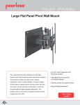
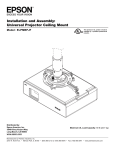
Installation and Assembly:
Structural Round Ceiling Plate
Model: ELPMBP03
R
This product is UL Listed. It must be
installed by a qualified professional
installer.
Maximum UL Load Capacity: 150 lb (68 kg)
Manufactured by Peerless Industries, Inc.
3215 W. North Ave. • Melrose Park, IL 60160 • (800) 865-2112 or (708) 865-8870 • Fax: (708) 865-2941 • www.peerlessmounts.com
ISSUED: 02-13-08 SHEET #: 054-9126-2 07-10-08
NOTE: Read entire instruction sheet before you start installation and assembly.
WARNING
• Do not begin to install your product until you have read and understood the instructions and warnings contained in this
Installation Sheet. If you have any questions regarding any of the instructions or warnings, call Peerless customer care
at 1-800-729-0307.
• This product should only be installed by someone of good mechanical aptitude, has experience with basic building
construction, and fully understands these instructions.
• Make sure that the supporting surface will safely support the combined load of the equipment and all attached hardware and components.
• Never exceed the Maximum UL Load Capacity.
• If mounting to wood joists or wood beam ceilings, make sure that mounting screws are anchored into the center of the
joists or beams. Use of an "edge to edge" stud finder is highly recommended.
• Always use an assistant or mechanical lifting equipment to safely lift and position equipment.
• Tighten screws firmly, but do not overtighten. Overtightening can damage the items, greatly reducing their holding
power.
• This product is intended for indoor use only. Use of this product outdoors could lead to product failure and personal
injury.
• When installing or adjusting the ceiling mount, do not use adhesives, lubricants, or oils to prevent the screws from
loosening. If you use adhesives, lubricants, or oils to prevent the screws from loosening, the casing may crack and the
projector may fall, causing serious injury and damage to the projector.
Tools Needed for Assembly
•
•
•
•
•
•
stud finder ("edge to edge" stud finder is recommended)
phillips screwdriver
3/8" (10 mm) socket wrench
drill
1/4" bit for concrete surface
5/32" bit for wood studs
Table of Contents
Parts List .............................................................................................................................................................................. 3
Extension Column and Flush Mounting Applications ............................................................................................................ 4
Installation to Wood Joist Finished Ceilings, Exposed Wood Joists or Wood Beam Ceilings ............................................... 5
Installation to Solid Concrete ................................................................................................................................................ 6
Warranty Information ............................................................................................................................................................. 7
2 of 7
Visit the Peerless Web Site at www.peerlessmounts.com
ISSUED: 02-13-08 SHEET #: 054-9126-2 07-10-08
For Technical Support Contact Peerless Mounts at 1-800-729-0307 or 708-865-8870.
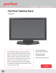
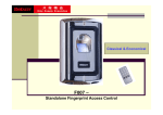
Before you begin, make sure all parts shown are included with your product.
Parts List
A
B
C
D
E
F
G
Description
round ceiling plate
#14 x 2.5" wood screw
M5 x .8 x 10 mm phillips screw
M5 x .8 x 10 mm socket pin screw
4 mm allen wrench
rubber grommet
concrete anchor
Qty.
1
4
1
1
1
1
4
Part #
055-2798
5S1-015-C04
520-2005
520-2031
560-9646
530-9401
590-0097
NOTE: Some parts may appear slightly different than illustrated.
A
F
B
D
C
E
G
3 of 7
Visit the Peerless Web Site at www.peerlessmounts.com
ISSUED: 02-13-08 SHEET #: 054-9126-2 07-10-08
For Technical Support Contact Peerless Mounts at 1-800-729-0307 or 708-865-8870.
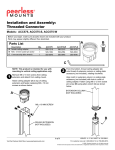
1
Place grommet (F) into hole of ceiling plate (A).
A
NOTE: Make sure grommet overlaps retaining
collar. Grommet may require some force to fit in
hole and will appear slightly deformed.
RETAINING
COLLAR
F
WARNING
• For safety, extension column must be locked to threaded fitting with screw.
Extension Column Applications
2
Insert end of extension column into threaded fitting of
ceiling plate (A). Tighten four or five complete turns.
Align slot in extension column with one of the small
holes in the side of the threaded fitting. Insert and
tighten one M5 x 10 mm phillips screw (C) into hole to
lock extension column to threaded fitting.
THREADED
FITTING
A
C
SLOT
NOTE: For security option, use M5 socket pin screw (D)
in place of screw (C). Tighten using 4 mm allen
wrench (E).
UL LISTED ELPMBC01 AND
EXT OR ADJ SEIRIES
(SOLD SEPARATELY)
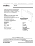
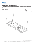
Flush Mounting Applications
2
Screw flush mount from top of ceiling plate (A) as
shown in fig. 2. Tighten four or five complete turns.
Align slot in flush mount tube with one of the small
holes in the side of the threaded fitting. Insert and
tighten one M5 x 10 mm phillips screw (C) into hole to
lock flush mount tube to threaded fitting.
NOTE: For security option, use M5 socket pin
screw (D) in place of screw (C). Tighten using 4 mm
allen wrench (E).
FLUSH MOUNT
TUBE (SOLD
SEPARATELY)
A
4 of 7
Visit the Peerless Web Site at www.peerlessmounts.com
fig. 2
ISSUED: 02-13-08 SHEET #: 054-9126-2 07-10-08
For Technical Support Contact Peerless Mounts at 1-800-729-0307 or 708-865-8870.
Installation to Wood Joist Finished Ceilings, Exposed Wood Joists,
or Wood Beam Ceilings
WARNING
• Installer must verify that the supporting surface will safely support the combined load of the equipment and all
attached hardware and components.
• Tighten wood screws so that ceiling plate is firmly attached, but do not overtighten. Overtightening can damage
the screws, greatly reducing their holding power.
• Never tighten in excess of 80 in. • lb (9 N.M.).
• Make sure that mounting screws are anchored into the center of the wood joist or wood beam. The use of an
"edge to edge" stud finder is highly recommended.
• Hardware provided is for attachment of mount through standard thickness drywall or plaster into wood joist or
wood beam ceilings. Installers are responsible to provide hardware for other types of mounting situations.
3
Drill two 5/32" (4 mm) dia. holes to a minimum depth of 2.5" (64 mm). Attach ceiling plate (A) to the joist center
using two #14 x 2.5" wood screws (B) as shown. Tighten wood screws (B) using 3/8" (10 mm) socket wrench so
ceiling plate (A) is firmly attached.
A
B
5 of 7
Visit the Peerless Web Site at www.peerlessmounts.com
ISSUED: 02-13-08 SHEET #: 054-9126-2 07-10-08
For Technical Support Contact Peerless Mounts at 1-800-729-0307 or 708-865-8870.
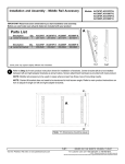
Installation to Solid Concrete
WARNING
• Concrete must be 2000 psi density minimum. Lighter density concrete may not hold concrete anchor.
• Make sure that the supporting surface will safely support the combined load of the equipment and all attached hardware and components.
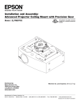
3
Use ceiling plate (A) as a template to mark holes.
Drill four 1/4" (6 mm) dia. holes to a minimum depth
of 2.5" (64 mm). Insert four anchors (G) in holes
flush with ceiling as shown in figure 3.1.
fig. 3.1
CONCRETE
CEILING
Place ceiling plate (A) over anchors (G) and secure
with #14 x 2.5" (6 mm x 65 mm) wood screws (B).
Tighten wood screws (B) using 3/8" (10 mm) socket
wrench to firmly attach ceiling plate (A).
G
Drill holes and insert anchors (G).
See figures 3.2 and 3.3.
fig. 3.2
A
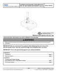
WARNING
• Always attach concrete anchors directly to load-bearing
concrete.
G
B
• Never attach concrete anchors to concrete covered with
plaster, drywall, or other finishing material. If mounting
to concrete surfaces covered with a finishing surface is
unavoidable, the finishing surface must be counterbored
as shown below. Be sure concrete anchors do not pull
away from concrete when tightening screws. If plaster/
drywall is thicker than 5/8", custom fasteners must be
supplied by installer. (Not evaluated by UL)
Place ceiling plate (A) over anchors (G) and secure with
screws (B).
fig. 3.3
WARNING
Tighten all fasteners.
• Tighten screws so that ceiling plate is firmly attached,
but do not overtighten. Overtightening can damage
screws, greatly reducing their holding power.
• Never tighten in excess of 80 in. • lb (9 N.M.).
CUTAWAY VIEW
INCORRECT
concrete
ceiling
plate
ceiling
plate
concrete
G
A
CORRECT
plaster/
drywall
plaster/
drywall
B
6 of 7
Visit the Peerless Web Site at www.peerlessmounts.com
ISSUED: 02-13-08 SHEET #: 054-9126-2 07-10-08
For Technical Support Contact Peerless Mounts at 1-800-729-0307 or 708-865-8870.
LIMITED FIVE-YEAR WARRANTY
3HHUOHVV,QGXVWULHV,QFHVWDEOLVKHVDZDUUDQW\SHULRGRIÀYH\HDUVIRUSURGXFWVPDQXIDFWXUHGRUVXSSOLHGE\3HHUOHVV7KLVSHULRGFRPPHQFHVIURPWKHGDWH
RIVDOHRIWKHSURGXFWWRWKHRULJLQDOFRQVXPHUEXWZLOOLQQRFDVHODVWIRUPRUHWKDQVL[\HDUVDIWHUWKHGDWHRIWKHSURGXFWҋVPDQXIDFWXUH'XULQJWKHZDUUDQW\
SHULRGVXFKSURGXFWVZLOOEHIUHHIURPGHIHFWVLQPDWHULDODQGZRUNPDQVKLSSURYLGHGWKH\DUHLQVWDOOHGDQGXVHGLQFRPSOLDQFHZLWKWKHLQVWUXFWLRQVHVWDEOLVKHGE\
3HHUOHVV,QGXVWULHV,QF6XEMHFWWRDSSOLFDEOHOHJDOUHTXLUHPHQWVGXULQJWKHZDUUDQW\SHULRG3HHUOHVVZLOOUHSDLURUUHSODFHRUUHIXQGWKHSXUFKDVHSULFHRIDQ\
VXFKSURGXFWZKLFKIDLOVWRFRQIRUPZLWKWKLVZDUUDQW\
$Q\RWKHUZDUUDQWLHVSUHVFULEHGE\WKHODZZKLFKPD\DSSO\ZLWKUHVSHFWWRVXFKSURGXFWVDOVRDUHOLPLWHGLQGXUDWLRQWRWKHZDUUDQW\SHULRGVSHFLÀHGLQWKLV/LPLWHG
)LYH<HDU:DUUDQW\
7KLVZDUUDQW\GRHVQRWFRYHUGDPDJHFDXVHGE\DVHUYLFHRUUHSDLUVE\WKHFXVWRPHURUDSHUVRQZKRLVQRWDXWKRUL]HGIRUVXFKVHUYLFHRUUHSDLUVE\3HHUOHVV
,QGXVWULHV,QFEWKHIDLOXUHWRXWLOL]HSURSHUSDFNLQJZKHQUHWXUQLQJWKHSURGXFWFLQFRUUHFWLQVWDOODWLRQRUWKHIDLOXUHWRIROORZ3HHUOHVVҋLQVWUXFWLRQVRUZDUQLQJV
ZKHQLQVWDOOLQJXVLQJRUVWRULQJWKHSURGXFWRUGPLVXVHRUDFFLGHQWLQWUDQVLWRURWKHUZLVHLQFOXGLQJLQFDVHVRIWKLUGSDUW\DFWLRQVDQGIRUFHPDMHXUH
,QQRHYHQWVKDOO3HHUOHVVEHOLDEOHIRULQFLGHQWDORUFRQVHTXHQWLDOGDPDJHVRUGDPDJHVDULVLQJIURPWKHWKHIWRIDQ\SURGXFWZKHWKHURUQRWVHFXUHGE\DVHFXULW\
GHYLFHZKLFKPD\EHLQFOXGHGZLWKWKHSURGXFW
7KLV/LPLWHG)LYH<HDU:DUUDQW\LVLQOLHXRIDOORWKHUZDUUDQWLHVH[SUHVVHGRULPSOLHGDQGLVWKHVROHUHPHG\ZLWKUHVSHFWWRSURGXFWGHIHFWV1RUHWDLOHUGHDOHU
GLVWULEXWRULQVWDOOHURURWKHUSHUVRQLVDXWKRUL]HGWRPRGLI\RUH[WHQGWKLVZDUUDQW\RULPSRVHDQ\REOLJDWLRQRQ3HHUOHVVLQFRQQHFWLRQZLWKWKHVDOHRIDQ\SURGXFW
PDQXIDFWXUHGRUVXSSOLHGE\3HHUOHVV
7KLVZDUUDQW\JLYHVVSHFLÀFOHJDOULJKWVDQG\RXPD\DOVRKDYHRWKHUULJKWVSURYLGHGE\WKHQDWLRQDOOHJLVODWLRQRIWKHFRXQWU\LQZKLFK\RXSXUFKDVHGVXFKSURGXFW
www.peerlessmounts.com
© 2007 Peerless Industries, Inc.
ISSUED 03/17/06 LIT-0190E
7 of 7
Visit the Peerless Web Site at www.peerlessmounts.com
ISSUED: 02-13-08 SHEET #: 054-9126-2 07-10-08
For Technical Support Contact Peerless Mounts at 1-800-729-0307 or 708-865-8870.
© 2008, Peerless Industries, Inc. All rights reserved.
All other brand and product names are trademarks or registered trademarks of their respective owners.