1
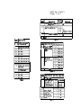
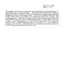
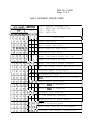
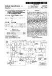
EPSON
EPSON AMERICA, INC.
INFORMATION
Product Support Bulletin
Subject: Priority Fax 1000 Maintenance Switch Function Tables
Date: 8/8/90
Page: 1 of 7
PSB No: P-0071
Originator: VB
The purpose of this document is to describe the PriorityFax IO00 maintenance
soft switch functions and to supply instructions for accessing them.
ACCESSING THE MAINTENANCE MODE
1. To enter the maintenance mode, apply AC power while pressing the
“FINE/PHOTO” and the “START/COPY” keys.
2. The unit will output a long beep and the “ERROR” LED will blink,
indicating the unit is in maintenance mode. If the unit does not enter
the maintenance mode call Epson Product Support at 213- 539 - 9955
for assistance.
3. There are 2 levels of soft switch functions accessible in the
maintenance mode. Table 1 lists the initial level functions. Tables 2,
3, and 4 list the second level functions. The tables are located at the
end of this document.
4. The following operations explain how to execute the first level soft
switch functions listed in Table 1.
A. In Table 1, the second digit of the “Switch Number” is the number
on the left. To enter a “1” as the second digit of the “Switch
Number”, press the “FINE/ PHOTO” key once. At this point, If the
“FINE/PHOTO” key is not pressed before the “START/COPY’ key,
the second digit remains as zero.
B. To Enter the first digit of the “Switch Number” press the
“START/COPY’ key the number of times equal to the first digit of
the “Switch Number” to be selected. To enter zero press the
“START/COPY” key10 times.
C. To complete the code entry, press the “FINE/PHOTO” key one time.
D. The unit returns to the initial maintenance mode when the number
entered does not correspond to a function listed in Table 1.
PSB No: P-0071
Page: 2 of 7
E. Pressing the “STOP” key in the initial maintenance mode returns the
unit to normal operation.
Pressing the ‘STOP” key when only one digit has been entered
returns the unit to normal operation.
F. The functions in Table 1 marked “NOT USED” are either not
available or require specialized equipment. They should only be
accessed by an authorized Epson Customer Care Center.
EEPROM PARAMETER INITIALIZATION
Function
Sets the EEPROM memory content, user switch data, and soft switch data
to the factory default settings.
Operation Method
1. To activate the EEPROM Parameter Initialization, enter the initial
maintenance mode. Press the START/COPY’ key one time and then
press the ‘FINE/PHOTO” key one time.
2. Upon completion of the parameter initialization, the unit will emit one
long beep indicating it has returned to the initial maintenance mode.
EEPROM WHITE LEVEL DATA INlTlALIZATION
Function
The unit scans a blank white sheet of paper to establish a while level
reference point that is used for comparison of black and white levels.
Operation Method
1. To activate the EEPROM White Level Data Initialization, enter the initial
maintenance mode. Load a blank white sheet of paper in the
document slot.
2. Press the “START/COPY’ key twice and then press the ‘FINE/PHOTO”
key one time.
3. Upon completion of the white level data initialization, the unit will emit
one long beep indicating it has returned to the initial maintenance
mode.
PSB No: P-0071
Page: 3 of 7
TRANSMISSION VERIFICATION REPORT
1. To set the Transmission Verification Report to “ON”, enter the initial
maintenance mode. Press the “START/COPY’ key 7 times and then
press the “FINE/PHOTO” key one time.
To set the Transmission Verification Report to “OFF”, enter the initial
maintenance mode. Press the “START/COPY’ key 8 times and then
press the “FINE/PHOTO” key one time.
2. Upon completion, the unit will print the change made and emit one
long beep indicating it has returned to the initial maintenance mode.
TEST PATTERN
1. To print the test pattern shown in Figure 1, enter the initial
maintenance mode. Press the “START/COPY’ key 9 times and then
press the “FINE/PHOTO” key one time.
2. Upon completion of the test pattern print out, the unit will emit one
long beep indicating it has returned to the initial maintenance mode.
SECOND LEVEL SOFT SWITCH FUNCTIONS
The second level of soft switch functions is accessed through switch 10 of
the initial level of function switches. Refer to Figure 2 for instructions on
accessing and changing these functions.
SECOND LEVEL SOFT SWITCH DATA PRINTOUT
1. To print the “System Configuration List” which contains the Second
Level Soft Switch Data, enter the initial maintenance mode. Press the
“PHOTO/FINE” key one time, press the “START/COPY” key one time
and then press the ‘PHOTO/FINE” key one time.
2. The unit will print the “System Configuration List” and emit one long
beep indicating it has returned to the initial maintenance mode.
PSB No: P-0071
Page: 4 of 7
SECOND LEVEL SOFT SWlTCH FUNCTION DESCRIPTIONS
TABLE 2 - Switch 1: Overseas communication mode (reception)
Setting switch 1 to a “1” allows the unit to acknowledge the 1100 Hz
signal that suppresses echoes, instead of a 2100 Hz which disables the
echo suppressor (ES). Suppressing the echoes provides a more
reliable method of establishing communications.
TABLE 2 - Switches 2 & 3: Overseas communication mode (Transmission)
When switch 2 is set to “1” and switch 3 is set to “0”, the unit ignores
the DIS signal sent from the calling station for suppressing echoes.
Note: Some called models may cause an error by receiving an echoed
DIS.
When both switches 2 and 3 are set to “1“, the unit transmits an 1100
Hz signal for 3 seconds upon detection of the DIS V.21 flag. This
operation prevents the called station from receiving its own DIS and
enables a no- carrier state until the unit transmits a subsequential DIS.
TABLE 2 - Switch 4: Direct connection mode
When switch 4 is set to 1, the unit starts receiving signals from the
remote station when the “START/COPY” key is pressed, regardless of
whether the hand set is on- hook or off- hook. This mode is used
for cross testing two fax machines when they are connected directly to
each other.
TABLE 3 - Switches 1 - 4: Stan/End Transmission speed in 63 mode
The starting and ending transmission speed can be set separately in
63 overseas communication mode. If there is excessive noise,
decrease the starting speed. Increase the ending speed if the
transmission of the document takes too long. These settings are
independent of the overseas communications mode (Table 2 switches 2
and 3).
PSB No: P-0071
Page: 5 of 7
TABLE 4 - Switches 3 & 4: Modem Equalizer
These switches are used for setting the modem equalizer to
compensate for line loss. The function section of Table 4 lists the
relationship between the line loss and the appropriate switch setting
that compensates for that loss.
TABLE 4 - Switches 5- 8: Modem Attenuator
These switches are used to adjust the transmission level attenuation.
The amount of attenuation is accumulative when setting more than one
switch to “1”. For example, if switches 5 and 6 are set to ‘1” and
switches 7 and 8 are set to “0”, the accumulative attenuation is 12 dB
The maximum attenuation with all the switches set to “1” is 15 dB.
When a switch in this section of Table 4 is set to “0”, that switch value
is 0 dB.
Figure 1
PSB No: P-0071
Page: 6 of 7
To enter Inttlal Halntenance Mode, Hold down the
FINE/PHOTO and START/COPY buttons while aoDlYlng Dower.
Initial Maintenance Mode
,
I
Press FINE/PHOTO 1 time
Press START/COPY 10 times
Press FINE/PHOTO 1 time
Sets second digit to 1
Sets first digit to 0
Completes code entry
Second level switches accessible
(OPTIONAL)
Press the FINE/PHOTO Button: l=Table 2
1, 2, or 3 times to select : P=Table 3
the desired switch bank.
(See Tables 2. 3, and 4)
i 3=Tab'e 4
Press the START/COPY button
To orrnt a SYSTEM
CONFIGURATION LIST:
Press FINE/PHOTO 1 tlme
Press START/COPY 1 time
Press FINE/PHOTO 1 tlcne
Enters selection
(Prints current switch status)
Refer to the System configuration
I 'Ii listortable 2. 3, or 4.
1 1 Press the START/COPY button 1
t
I
I1
Enters selection
I
Press the FINE/PHOTO button
once to select 1. Sk10 this
step to select 0.
Refer to table 2, 3, or 4 for
more detail.
1
Press the START/COPY button
Enters selection
Press START/COPY to set
other switches.
I
Press STOP to exit
I current switch bank. I
Pressing STOP will print
switch status
I
Press STOP to exit Initial Maintenance Mode
Figure 2
Returns the unit to normal
ooeration.
PSB No: P-0071
Page: 7 of 7
I I
Switch
nuler
Dorcriptim
Ructch '
IRotting I
Fuwxion
O V E R S E A S -ICATlOR 0
‘Off
RODE (Rraption)
101
I
I
DIRECT CONYECTIOll #OE
I
1 S-8 1 ROT USED
Suitch' Faction
Naber Dercriptim
I I
I I
01
EEPR# PMMETER
lYfTlAlIzATlw
OATA lYtllALl2ATlw
DATA PRIWTM
I
I
I
I I
BUCriptim
II
bpottha
etert of a3
nicatiam
&itch
wr
1,2
5-a 1
Suit&
T&k 1
0
OFF
low
I
ROT URED
IRider I
Ooacriptim
I 1*2 I
ROTWED
3.4
I
I
Switch
IRating I
Fmctian
II
I
I
1 Lim Lou
EPSON
EPSON AMERICA, INC.
Product Support Bulletin
Subject: PriorityFax 1000 Equipment Error Codes
Date: 3/7/90
Page: 1 of 3
PSB No: P-0061
Originator: VB
This product support bulletin explains the procedure for reading and interpreting
PriorityFax 1000 (PF1000) error codes.
The PF1000 equipment error codes are listed under the “Error Codes” column in
Table 1.
When the PF1000 is in error mode, the buzzer sounds and the “ERROR’ LED
turns ON. Simultaneously pressing and holding the “FINE/PHOTO” and the
“START/COPY” buttons until the buzzer stops sounding, sets the PF1000 into an
error code display mode.
In the error code display mode, the state of the “SENDING DOCUMENT”,
“RECEIVING DOCUMENT”, “FINE”, and “PHOTO” LEDs on the front panel reflect
the error condition of the PF1000. If an LED is ON it represents a “1”, if it is
OFF it represents a “0”. Use Columns 0 through 7 of Table 1 to interpret the
error code.
The LEDs display the error code in 2 parts. The state of the “ADD PAPER” LED,
which changes in 5 second intervals, determines which part of the error code is
being displayed.
1. When the “ADD PAPER” LED is ON the “PHOTO”, “FINE”, “RECEIVE
DOCUMENT”, and “SEND DOCUMENT LEDs represent columns 0, 1, 2, 3
of Table 1.
2. When the “ADD PAPER” LED is OFF the “PHOTO”, “FINE”, “RECEIVE
DOCUMENT”, and “SEND DOCUMENT LEDs represent the columns 4, 5, 6,
7 of Table 1.
PSB No: P-0061
Page: 2 of 3
For example, if a document is being sent and is not detected by document sensor 2,
the PF1000 will go into error mode.
Simultaneously pressing and holding the
FINE/PHOTO and the START/COPY buttons until the buzzer stops sounding, sets the
PF1000 into an error code display mode. In this error condition, when the “ADD
PAPER” LED is ON, only the “PHOTO” and “FINE” LEDs will be ON. In Table 1, This
is interpreted as a “1” for columns 0 and 1 and a “0” for columns 2 and 3. When the
“ADD PAPER” LED is OFF, only the “SEND DOCUMENT” and “FINE” LED’s will be ON.
In Table 1, this is interpreted as a “1” for columns 5 and 7 and a “0” for columns 4
and 6. In Table 1, locate the Row that has a “1” in columns 0, 1, 5, and 7 and a “0”
in columns 2, 3, 4, and 6. Notice that this row corresponds to the same row that lists
the “Doc. sensor 2 not detecting document” error.
PSB No: P-0061
Page: 3 of 3
Table 1 EQUIPMENT ERROR CODES
*SD
*RD
*FN
*PH
1 .STATE
ON
=
=
=
=
SENDING DOCUMENT LED
RECEIVING DOCUMENT LED
FINE LED
PHOTO LED
RDIFN(PH
Error Codes
1 0 0 0 1
1 0 0 0 1
1 0 0 0 1
10
0
01
i#E
0
0
0
Paper jam error
0
0
1
Auto cutter jam error
0
1
0
Head connector open error
0
1
1
Thermistor heat error
o!
0 1
Paper low sensor output too low
t1 0
Paper low sensor to high
l!
1
I
Paper low sensor output unstable
1 0 1 Paper low sensor black and white error
0 0 1 Recording paper cover open
I##
1 0 1 0
0
0
1
0
Document too long
1 0 1 0
0
0
1
1
Dot. sensor 2 not detecting document
1 0 1 0
0
11 01 011 Faulty white level data
1
0
1
Faulty DMA0 in scanning
1
1
0
Faulty DMA1 in scanning
11
1
Document feed time-out
0
0
0
1 line scanning time-out
1
0
1
Over-heating of power supply
11
II 01 0111
Out of recording paper
11 l( 011 White level data error in EEPROM
01 4 OII
Document lost during transmission
I