1
U.S. Department of Transportation
Docket Management Facility West Building Ground Floor Room W12-140
1200 New Jersey Avenue,S.E.
Washington, D.C. 20590
Dear Sir or Madam:
Pursuant to Section 333 of the FAA Modernization and Reform Act of 2012 (the
Reform Act) and 14 C.P.R. Part 11, Aerial Intelligence HD, LLC ("AIHD, LLC"),
hereby applies for an exemption from the listed Federal Aviation Regulations
("FARs").
Aerial Intelligence HD, LLC ("Petitioner") hereby applies for an
exemption in order to conduct commercial use operations with unmanned aerial
systems ("UAS"). In accordance with the requirements of the Federal Aviation
Administration ("FAA"), Petitioner's UAS operations have been designed to
achieve a level of safety equivalent to that provided by the FAA regulations from
which an exemption is requested.
Attached please find Petitioner's request for an exemption from the listed Federal
Aviation Regulations to allow commer~ial operation
its small Unmanned Aircraft
Systems ("sUAS") for aerial imaging for agr,i.cultural analysis and rural farm safety
and monitoring of secured and controlled enVironmental areas. The sUAS will be
flown exclusively in Class G airspace for this purpose. This exemption request is also
exclusively for the use of the UAS manufactured by Turbo Ace, lhc. - model Turbo
Ace Cinewing 6 HL.
of
Attached to this letter is the Turbo Ace, Inc. UAS Flight Manual ("Manual"), which
outlines the operqtirig requirements, limitation~,. and technical specifications for the
Turbo Ace system. d~rierJQp~rat,or:ptAIHD,.~Lp.•Js a licen~ed, degreed
( BS ME) Profess io na I Meehan i c'a(]::ng i ne·~r •iarrd ·has reviewed this Manual
and found it to be acceptable for sUAS operations on its secure project sites.
Thank you for your time and consideration.
Sincerely,
~-~Thomas Hotard, P.E.
Owner/Operator
Aerial Intelligence HD, LLC
19257 252nd Ave
Bettendorf, lA 52722
Cc: John S. Duncan
Director, Flight Standards Service
Congressman: Dave Loebsack
Page 1 of 10
Aerial Intelligence HD, LLC
Proposed Commercial Uses
Petitioner proposes to use the Turbo Ace Cinewing 6 HL small UAS aircraft for multiple
commercial applications, including safety inspections and aerial surveying of the
following remote or difficult-to-access facilities:
•
•
•
•
•
•
•
Rural farms with low population density;
Silos/stacks;
Grain elevators;
Pipelines;
Power lines and cell towers;
Bridges;
Wind turbines.
Petitioner also may use UAS operations in support of emergency response activities on
behalf of The Department of Agriculture, The Department of the Interior's Bureau
of Safety and Environmental Enforcement, and any other federal or state government
agency which may require its services and personnel. All of Petitioner's proposed UAS
operations are intended to facilitate safety inspections and aerial surveying in areas
where the performance of those functions using current methods involves considerable
expense and/or a substantial risk of injury. Many. of these functions must be performed
in hazardous environments by human interaction. Others may be performed much
more efficiently with an unmanned aircraft with the ability to hover and capture images
at close range. The commercial UAS applications that Petitioner proposes will therefore
result in a significant enhancement of safety, by reducing the risks associated with
current inspection methods and enhancing current inspection techniques.
Proposed UAS Aircraft
Petitioner plans to tondJcf c<:>rrul1er¢ial UA9 operation.s with tl}e Tur;bo Ace Cinewing 6
HL aircraft. The Turbo Ace Cinewing 6 HL is a small lJAS··with a maximum takeoff
weight of 20.6 lbs. At all times, while conducting commercial operations, Petitioner will
operate the Turbo Ace Cinewing 6 HL under line-of-sight conditions with a hands-on
control and in response to commands from a Petitioner employee with specialized flight
training. Aircraft will perform commercial operations autonomously or in accordance
with a pre-programmed flight plan. If the motors on the aircraft experience a power loss
within 20% of empty, the Turbo Ace Cinewing 6 HL has an audible and tactile alarm and
failsafe home return system. In the event that the signal between the control system and
the Turbo Ace Cinewing 6 HL is lost or disrupted, the aircraft is designed to hover for
approximately 5 seconds attempting to regain the data link. If the UAS, which is
equipped with a GPS communication system, is unable to re-establish contact with the
control station, it will rely on an auto-pilot feature that returns the UAS to the home point
via the original flight path from the launch point. This will eliminate "fly-away" incidents
and other flight deviations that are known to occur with other types of UAS aircraft.
The Turbo Ace Cinewing 6 HL using a NAZA M V2 control has been used for
commercial cinematography and survey work due to both platforms being stable and
simple to operate. The NAZA M control system has substantial commercial
operating duty cycles inside the U.S. and is known for being rugged with a history of
reliability in flight.
Page 2 of 10
Aerial Intelligence HD, LLC
Operating Conditions
Petitioner will conduct commercial operations with the Turbo Ace Cinewing 6 HL only in
accordance with a highly-detailed set of safeguards governing all phases of flight
operations. Petitioner employees responsible for UAS operations will always place a
priority upon minimizing risk to personnel, equipment, assets and the environment.
To ensure the highest level of safety, UAS flight operations will only be conducted after
an extensive safety briefing (including Petitioner and customer personnel) and a risk
analysis has been conducted. A majority of Petitioner's operations will be in sparsely
populated rural agricultural areas that pose no risk of injuries to humans.
All UAS flights operated by Petitioner will be conducted by a minimum of two
operational personnel, including a system supervisor. No flights may be initiated
unless a preflight checklist has been completed and signed by all those Petitioner
employees performing the checks. The checklist procedure includes a detailed
inspection of the Turbo Ace Cinewing 6 HL prior to the initiation of any operations.
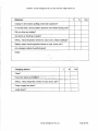
Attached as Exhibit A to this exemption petition, is a copy of Aerial Intelligence HD,
LLC's pre-flight and post-flight checklist. Any UAS operations to be conducted at an
altitude of more than ten feet require the prior approval of Petitioner supervisory
personnel. Most importantly, from a safety perspective, operations directly overhead
Petitioner and customer personnel are not permitted as the UAS aircraft must be
operated at all times at no more than a 30 degree oblique to any personnel.
There are several additional mandates that Petitioner employees will observe in
connection with all commercial operations with the Turbo Ace Cinewing 6 HL, including
the following:
•
•
•
•
•
•
•
•
No flights thr.()!-lgtl an established Air Defense Identification Zone (ADIZ);
UAS flights sf'lan,:n6t,.]exceed' LJ:OO f~et C!bove. ground or above the
sea level per FAA Advisory Circular 9'1'-57;' ',
All flights will be conducted in Class G airspace;
All flights will be conducted within line-of-sight of UAS operator;
All flights will be conducted in accordance with Class G airspace visibility
requirements;
Wind speed shall not exceed 25 knots;
UAS operations will be conducted during daylight hours;
A Notice to Airmen {NOTAM) will be filed with the FAA prior to each UAS
operation;
At no point in time will Aerial Intelligence, HD's UAS aircraft be allowed to share airspace
with commercial aircraft. Prior to conducting operations within three miles from any
airport runway, Petitioner will notify the airport operator or the airport tower, as the
case may be, in compliance with FAA Advisory Circular 91-57. Petitioner employees
will terminate any UAS operations when an approaching commercial aircraft is within
five nautical miles.
Page 3 oflO
Aerial Intelligence HD, LLC
Operator Requirements
Aerial Intelligence HD, LLC's commercial UAS operations will build on its years of
experience as a Licensed, Professional Mechanical Engineer. Only Petitioner employees
who have undergone and successfully completed a rigorous competency assessment
evaluation will be selected to operate the Turbo Ace Cinewing 6 HL. Operators must
demonstrate not only a superior knowledge of the technical issues associated with UAS
systems, including the full range of the capabilities and limitations of the Turbo Ace
Cinewing 6 HL aircraft, but also must show sound piloting techniques and the ability to
navigate around structures.
Petitioner employees conducting UAS commercial
operations will enforce compliance more stringently than written and not accept
that "compliance means safe".
The Petitioner operators of the Turbo Ace Cinewing 6 HL have previous significant
experience as the operators of the equipment. Any operator of the Turbo Ace Cinewing 6
HL will undergo a program of simulator training as well as hands- on flight training in a
simulated inspection environment. Simulator training will allow these employees to
gain experience with the specific flight characteristics of the Turbo Ace Cinewing 6 HL
prior to any actual commercial operations.
The following requirements will apply to any .commercial UAS operations conducted by
Petitioner:
• A pilot-in-command (PIC) will be designated at all times for each flight;
• The PIC will be directly responsible for, and have final authority over the
operation of the UAS;
• The PIC will not perform concurrent duties as the visual observer;
• The PIC will be qualified on the Turbo Ace Cint;lwing 6 HL;
• The PIC will exerci:Se'.gpnJroi
UAS as it will not maneuver autonomously .
1:0verthe
. t ', ';; '-, '' ',
;
-~
f-' ;
"
'
.,
.
Given technical education, trainingandpersonaland prbfe~sibnal safety record, the amount
of required training, and the operational procedures applicable to Petitioner operating
the Turbo Ace Cinewing 6 HL for commercial purposes, Petitioner PIC's should not be
required to hold an FAA pilot certificate. The commercial UAS operations by Petitioner
will resemble the circumstances under which the FAA will issue a Certificate of Waiver or
Authorization to UAS operators without requiring pilot certification. All operations will
be in Class G airspace, conducted during daylight hours under visual line-of-sight flight
procedures no more than one-half nautical mile laterally from the Petitioner PIC.
The manager for Aerial Intelligence HD, LLC's commercial UAS operations is Thomas
Hotard, P.E. Mr. Hotard is a degreed Mechanical Engineer (BSME) has over thirty years
of experience designing, testing, and operating microprocessor-controlled industrial
equipment and components.
Page 4 of 10
Aerial Intelligence HD, LLC
Exemption Request Summary
Petitioner is requesting an exemption from FAA regulations in order to conduct
commercial UAS operations with a Turbo Ace Cinewing 6 HL. Attached below is a list of
each FAA regulation from which the Petitioner is requesting an exemption and the
justification for each such exemption. In accordance with FAA requirements, in the case
of each requested exemption, Petitioner is suggesting alternate methods of compliance
that will provide a level of safety equivalent to that provided by the regulation from
which an exemption is sought.
Petitioner's request is consistent with the FAA's policies for the granting of exemptions.
It also is in accordance with the direction provided by Congress in Section 333 of the
FAA Modernization and Reform Act of 2012 ("FAA Modernization Act"), instructing the
Secretary of Transportation to determine which UAS aircraft operating within visual line
of sight may be integrated into the National Airspace System NAS before the
development of regulations governing the commercial use of other types of UAS
aircraft.
Because of the relatively small size, light weight, speed and operational
capabilities of the Turbo Ace Cinewing 6 HL, as well as the strict visual line of sight
protocols under which these UAS will be operated by Petitioner, the Turbo Ace Cinewing
6 HL aircraft may be safely operated without c~eating a hazard to other users of the NAS
or a threat to national security. The Turbo Ace Cinewing 6 HL, operated as proposed
herein, is therefore the type of UAS that ought to be the subject of operational
approval by the Department of Transportation prior to the issuance of regulations
governing the operation of small, unmanned aircraft systems generally.
The UAS operations to be conducted by Petitioner pursuant to the requested exemption
offer significant safety .enhancements over current methods of providing the same
commercial serviCE;lS. ; ~u,rbo Acf9 ,qinewing
HL. aircraft have the ability to fly into
difficult-to-access areas that · prese'rit sut:>§fanti§lY h~~ard~ to. other methods of data
collection, including those involving close-up inspections by human beings. In evaluating
Petitioner's request for an exemption, the FAA should consider not just the ability of
Petitioner to achieve a level of safety equivalent to that afforded by the regulations from
which an exemption is sought, but also the safety benefits to be derived from using UAS
aircraft for services now performed by other means at substantially greater risk to
human life. As demonstrated below, the FAA can allow these benefits to be realized
without compromising its obligation to promote the highest level of aviation safety.
?
Respectfully submitted,
Thomas Hotard, P.E.
Owner/Operator
Aerial Intelligence, HD LLC
Page 5 of 10
Aerial Intelligence HD, LLC
AERIAL INTELLIGENCE HD, LLC-ITEMIZED EXEMPTION REQUESTS
Aerial Intelligence HD, LLC requests an exemption from the following regulations of the
Federal Aviation Administration:
14 C.F.R. § 45.23(b)- Display of marks: general
This regulation requires the display of an "N" registration mark on any U.S.-registered
aircraft. Additional markings are required for limited or restricted category aircraft,
experimental aircraft or provisionally-certificated aircraft on the entrance to the cabin,
cockpit or pilot station.
Referencing Exemption 11109 Regulatory Docket No. FAA-2014-0507, In the matter of the petition
of CLAYCO, INC.
Regarding the petitioner's requested relief from 14 CFR 45 .23(b) Display of marks, the petitioner requests this
relief under the assumption that marking with the word "experimental" will be required as a condition of a grant
of exemption. However, this marking is reserved for aircraft that are issued experimental certificates under 14
CFR 21.191. The petitioner's UAS will not be certificated under § 21.191, and therefore the "experimental"
marking is not required. Since the petitioner's UAS will not be certificated under§ 21.191, a grant of exemption
for § 45.23(b) is not necessary.
Equivalent level of safety analysis: The sUrface area of the Turbo Ace Cinewing 6 HL is
not large enough to contain any of the markings required by the FAA for limited or
restricted category aircraft, experimental aircraft or provisionally-certificated aircraft.
One of the purposes served by these markings is to caution passengers on board such an
aircraft (including any pilot) that it does not meet all of the FAA's requirements for a
standard category certificate of airworthiness. As the Turbo Ace Cinewing 6 HL will not
carry any passengers, and otherwise will operate in accordance with strictly-controlled
flight parameters, the ,§lbsemce of Tucl) a warning on the Turb.o Ace Cinewing 6 HL will
·
not result in any retluctidn in the :<:m~rall saf~tY ofJne:o,per:atiqn.
Petitioner is willing to include any markings that may be required by the FAA in
connection with its commercial UAS operations, with the understanding that the surface
area of the Turbo Ace Cinewing 6 HL will not permit lettering that is larger than one inch
in height. In addition, if requested by the FAA, Petitioner can place markings on each of
the control stations used to operate Petitioner's UAS aircraft.
14 C.F.R. Part 21, Subpart H: Airworthiness Certificates
14 C.F.R. § 91.203: Civil Aircraft: Certifications Required
Under 14 C.F.R. § 91.203, all U.S.-registered aircraft are required to have a certificate of
airworthiness issued by the FAA. Part 21, Subpart H of the FAA's regulations establishes
the procedural requirements for the issuance of airworthiness certificates by the FAA.
Referencing Exemption 11109 Regulatory Docket No. FAA-2014-0507, In the matter of the petition
of CLAYCO, INC.
The petitioner requested relief from 14 CFR part 21, Certification procedures for products and parts. In
accordance with the statutory criteria provided in Section 333 ofP.L. 112-95 in reference to 49 USC § 44704,
and in consideration of the size, weight, speed, and limited operating area associated with the aircraft and its
operation, the Secretary of Transportation has determined that this aircraft meets the conditions of Section 333.
Page 6 of 10
Aerial Intelligence HD, LLC
Therefore, the FAA fmds that the requested relief from 14 CFR part 21, and any associated noise certification
and testing requirements of part 36, is not necessary.
Equivalent level of safety analysis: The strict operational limitations under which
Petitioner will conduct flights for commercial UAS applications (e.g., daylight
operations, use of Class G airspace, all flights within line- of-sight of the operator) are at
least as restrictive as the limitations that apply to the operation of limited or restricted
category, experimental or provisionally-certificated aircraft. The Turbo Ace Cinewing 6
HL does not carry a pilot or any other passengers and their small size and electric motor
reduce the danger that any collisions with the ground or structures will involve anything
more than the loss of the sUAS.
14 C.F.R. § 61.133(a): Commercial Pilot Privileges and limitations
FAA regulations generally require that an aircraft may engage in operations for
compensation or hire only if it is flown by a person holding a commercial pilot
certificate. 14 C.F.R. § 61.133(a). Petitioner submits that hands-on experience with the
flight characteristics of the Turbo Ace Cinewing 6 HL and UAS aircraft generally are a far
more effective guarantee of flight safety than a pilot certificate would be in connection
with Aerial Intelligence HD, LLC's proposed commercial UAS services.
Equivalent level of safety analysis. A UAS, such as the Turbo Ace Cinewing 6 HL has flight
characteristics substantially different from manned aircraft. The propulsion system and
control surfaces on the Turbo Ace Cinewing 6 HL respond to inputs ·that are transmitted
remotely from the joy stick located on the control station. A pilot license of any kind
would not be useful in the actual operation of the ~UAS. An operator who had done all
his training on the Turbo Ace Cinewing 6 HL, with no previous flight experience with
manned aircraft, would have no preconceived notions or training to ignore and would be
intimately familiar with maneuvering the Turbo Ace Cinewing 6 HL.
Aerial Intelligence HD, LtC eh1plby~eJ6perator. Will , aqt a~ an ope~ator of Turbo Ace
Cinewing 6 HL 6 HL commercially after successfully completing a minimum of 20 hours
of UAS training flights. The above-listed hours will be recorded in logbooks subject to
inspection by FAA personnel at any time.
By requiring extensive flight experience with the Turbo Ace Cinewing 6 HL prior to
conducting commercial operations, Petitioner will have a better grasp of the handling of
that aircraft and the available options in the event of an emergency than they would by
holding a commercial pilot certificate for an entirely different type of airborne system.
14 C.F.R. § 91.7(a): Civil Aircraft Airworthiness.
This regulation prohibits the operation of an aircraft unless it is in an airworthy
condition. The Turbo Ace Cinewing 6 HL 6 HL will not be the subject of an airworthiness
certification process prior to their use by 01 for commercial UAS services.
Referencing Exemption 11109 Regulatory Docket No. FAA-2014-0507, In the matter of the petition
of CLAYCO, INC.
Regarding the petitioner's requested relief from 14 CFR 91.7(a) Civil aircraft airworthiness, Clayco's request
is based on its belief that "no FAA regulatory standard will exist for determining airworthiness," of the
Page 7 oflO
Aerial Intelligence HD, LLC
Skycatch UAS. It claims an equivalent level of safety will be provided, "given the size of the aircraft and the
requirements contained in the Manual for maintenance and use of safety checklists prior to each flight, as set
forth in the Section B and Section G." While the UAS will not require an airworthiness certificate in
accordance with 14 CFR part 21, Subpart H, the FAA considers the petitioner's compliance with its Flight
Manual (hereinafter referred to as the operator's manual) to be sufficient means for determining an airworthy
condition in accordance with § 91.7(a). Therefore, relief from § 91.7(a) is granted. The petitioner is still
required to ensure that its aircraft is in an airworthy condition - based on compliance with manuals and
checklists identified above- prior to every flight.
Equivalent level of safety analysis. As there will be no airworthiness certificate issued
for the aircraft, should this exemption be granted, no FAA regulatory standard
will exist for determining airworthiness. Given the size of the aircraft and the requirements
contained in the Operator's Manual for maintenance and use of safety check lists prior to
each flight, an equivalent level of safety will be provided during operation of the sUAS
14 C.F .R. § 91.9{b}(2): Civil Aircraft Flight Manual, Marking and Placard Requirements.
This regulation requires that an approved flight manual, manual material, markings,
placards or some combination thereof be placed onboard the aircraft. The Turbo Ace
Cinewing 6 HL has a configuration suitable for compliance with this requirement.
Referencing Exemption 11109 Regulatory Docket No. FAA'"'-2014-:-0507, In the matter of the petition
of CLAYCO, INC.
The petitioner requested relief from 14 CFR 91.9(b)(2) Civil aircraft flight manual, marking and placard
requirements and 14 CFR 91.203(a) and (b) Civil aircraft: Certifications required. Based on the FAA Memorandum
"Interpretation regarding whether certain required documents may b<; kept at an UA's control station," dated August 8,
2014, the requested relief from§§ 91.9(b)(2) and 91.203(a) and (b) is not necessary.
14 C.F.R. § 91.109(a) and 14 C.F.R. § 91.109{c): Flight Instruction: Simulated
Instrument Flight and ~ertain Flight Tests.
~ir~,r~ft ~~~~<for ~r~fnfng'~l:l'~~~se~'rY:!ust
.have 'dual flight controls,
Under this regulation,
subject to certain exceptions. FAA regulations also require that whenever training is
provided in a simulator, the simulator must have a second control seat occupied by a
safety pilot who possesses at least a private pilot certificate with category and class
ratings appropriate to the aircraft being flown.
Equivalent level of safety analysis. Petitioner has flight instruction training program for
its employees who will conduct commercial UAS operations. Pilots will be required to
perform frequent training flights and refresher flights in a sterile environment with
suitable objects for pilots to navigate to and around in a simulated commercial
environment.
The requirement for dual flight controls on an aircraft used for training purposes is
mitigated by the Turbo Ace Cinewing 6 HL's limited operational range, small dimensions
and the use of lightweight construction materials, all of which reduce the risk of
damage to surrounding structures in the event of an operator error that results in the
loss of the aircraft.
Page 8 of 10
Aerial Intelligence HD, LLC
14 C.F .R. 91.119: Minimum Safe Altitudes: General
This regulation specifies the minimum altitude in various flight environments below
which aircraft are not allowed to operate. Petitioner will conduct the commercial
services it proposes to operate below the FAA-specified minimum of 400 feet AGL and
closer to vessels and structures than the minimum separation of 400 feet mandated by
the FAA.
Equivalent level of safety analysis. The operation of the Turbo Ace Cinewing 6 HL
aircraft exclusively in Class G airspace (i.e., below 400 feet) is intended as a safety
measure to provide a level of separation between Aerial Intelligence HD's commercial
UAS operations and the operation of manned aircraft at altitudes above 400 feet.
Limiting the Turbo Ace Cinewing 6 HL to flights below the 400-foot AGL will enhance
safety rather than compromise it. The risk of damage to any nearby structures or
facilities is reduced by Turbo Ace Cinewing 6 HL's limited operational range, small
dimensions and the use of lightweight materials in their construction. Petitioner
requests narrowing separation from fixed structures to 100 feet in order to properly
inspect said structure.
14 C.F.R.§ 91.121: Altimeter Settings
Pursuant to this regulation, an aircraft that is operating below 18,000 feet above Mean
Sea Level must contain an altimeter that is set to one of several designated altimeter
settings prior to departure. The Turbo Ace Cinewing 6 HL for use in the Petitioner's
operation includes provisions for an altimeter. This telemetry will be provided if
deemed necessary.
Equivalent level of safety analysis: The operation of the Turbo Ace Cinewing 6 HL
sUAS exclusively in Cla~s G ~irspace ~(i.e., below 4.00 feet) away from commercial
traffic and ATC-controllecf;aitsplitc~. reduces the n~.ed, for an altimeter onboard
Petitioner's UAS aircraft. The altitude ofPetitioner's UAS aircraft above Mean Sea
Level and its GPS coordinates will be displayed on the screen of the remote control
station used by the operator to perform any commercial services. The operator will
have continuous situational awareness of the UAS altitude and position as flight
operations will be conducted under line- of-sight flight procedures.
14 C.F.R. § 91.151(a): Fuel Requirements for Flight in VFR Conditions.
FAA regulations require that a rotorcraft operating under VFR conditions have
sufficient fuel to fly to the first point of intended landing and, assuming normal cruising
speed, to fly for at least an additional 30 minutes. Turbo Ace Cinewing 6 HL has a
maximum operating time of 30 minutes.
Equivalent level of safety analysis. The FAA's regulations require sufficient reserves of
additional fuel to enable a rotorcraft to find the nearest suitable landing zone if the
intended landing facility is not available. The additional time that a multirotor is
required to be able to operate is less than the time required to allow fixed-wing aircraft
to find a suitable landing field (30 minutes during the day). Petitioner will perform
commercial operations autonomously or in accordance with a pre-programmed flight
plan. If the motors on the aircraft experience a power loss within 20% of empty, the
Page 9 of 10
Aerial Intelligence HD, LLC
Turbo Ace Cinewing 6 HL has an audible and tactile alarm and failsafe home return system
to ensure that the sUAS will have ample power and time required for a safe landing from the
original open take-off area.
14 C.F.R. § 91.203(a} & (b): Civil Aircraft: Certifications Required.
The FAA requires that all civil aircraft have an appropriate and current airworthiness
certificate and that the airworthiness certificate or special flight authorization for an
aircraft be displayed at the cabin or cockpit entrance so that it is visible to passengers or
crew. The Turbo Ace Cinewing 6 HL does not have a current airworthiness certificate
nor do they have a surface area large enough to display a certificate of airworthiness or
special flight authorization.
Equivalent level of safety analysis. The strict operational limitations under which
Petitioner will conduct
flights for commercial UAS applications (e.g., daylight
operations, use of Class G airspace, all flights within line- of-sight of the operator) are at
least as restrictive as the limitations that apply to the operation of aircraft that have
been issued limited or restricted category, experimental or provisional certificates of
airworthiness.
14 C.F.R. § 91.405(a}; 407(a}(1}; 409(a)(2);417(a}: Aircraft Maintenance and
Inspections: Maintenance Records.
FAA regulations impose various requirements regarding the maintenance of civil
aircraft, including periodic inspections, approval for return to service by a qualified
mechanic following maintenance or repair, an ainl)lorthiness inspection and certain rules
concerning maintenance recordkeeping. Petitioner's maintenance of its Turbo Ace
Cinewing 6 HL will not satisfy these requirements.
Equivalent level of safety analysis':' .Petitic;m,er I,Nill maintainthe Turbo Ace Cinewing 6 HL
in accordance with. the .. man·~als 'anel' operating .handt;)ook provided by the
manufacturer. Because of the Turbo Ace Cinewing 6 HL's small size and lightweight
construction, Petitioner will be able to subject it to top-to-bottom examination after
every flight. All pre- or post-flight maintenance, equipment failures, charge cycle logs,
fault/repair logs, inspections and general maintenance records will be kept on file for a
minimum of three years. Petitioner has developed a lengthy pre/post-flight checklist;
any sUAS which is unable to meet all the requirements for safe operation will be
removed from service immediately and will not return to service until any defects have
been remedied
If any parts have been updated by the manufacturer, Petitioner agrees to immediately
place them on the sUAS if its purpose is to ensure its UAS has the most recent
equipment and software to provide for public safety.
The number of hours that a sUAS has been in operation is logged by Petitioner to
ensure proper life of components as well as the flight packs that provide power.
Page 10 of 10
Aerial Intelligence HD, LLC
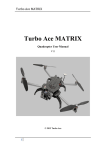
Turbo Ace CINEWING 6
Turbo Ace CINEWING 6
Hexacopter User Manual
V28
1
Turbo Ace CINEWIN G 6
Copyright 2013 Turbo Ace
Table of Contents
INTRODUCTION ......................................................................................................... 4
1.1 Welcome to the World of Hexacopters ........................................................... .4
1.2 Important Instructions ...................................................................................... 4
1.3 Quick Start ....................................................................................................... 8
1.4 Features .......................................................................................................... 10
1.5 Specifications ................................................................................................. 11
1.6 Flight controller specification .................................................... :................... 11
1. 7 Packing List. ................................................................................................... 12
1. 8 Caution & Safety ............................................................................................ 13
1.9 DOA (Dead-On-Arrival) Claim ..................................................................... 14
DIAGRAMS & PARTS ............................................................................................... 16
2.1 Top View ........................................................................................................ 16
2.2 Right-Side View ............................................................................................. 17
2.3 Rear View ...................................................................................................... 17
2.4 Part Specification ........................................................................................... 18
2.5 Technical Parameters ..................................................................................... 19
CINEWING 6 SETUP ................................................................................................. 20
3.1 Unpacking the CINEWING 6 ........................................................................ 20
3.2 Mounting Propellers ....................................................................................... 20
3.4 Battery Requirements & Installation .............................................................. 21
ELECTRONICS SETUP & ADJUSTMENT .............................................................. 22
4.1 ESC Programming for Spektrum DX 8 Transmitter (Required Setup For
ARF) ..................................................................................................................... 22
4.1 ESC Programming for Futaba 14SG Transmitter (Required For ARF) ........ 24
4.2 Transmitter Calibration for Spektrum DX 8 Transmitter (Required Setup For
ARF) ..................................................................................................................... 25
4.2 Transmitter Calibration for Futaba 14SG Transmitter (Required Setup For
ARF) ..................................................................................................................... 31
4.3 Transmitter & Receiver Compatibility Table (For ARF Only) ..................... 36
4.4 Receiver, Flight Controller & Auto-stabilization Setup for Spektrum DX8 .36
4.4 Receiver, Flight Controller & Auto-stabilization Setup for Futaba 14SG ..... 39
4.5 Transmitter Settings (For ARF Only) ........................................................... .41
4.6 Transmitter Flight Control & Gain Adjustments (For ARF Only) ............... .42
4.7 GPS Calibration ............................................................................................. 43
2
Turbo Ace CINEWING 6
4.8 CINEWING 6 Wiring Connection Chart for Spektrum DX 8 & AR8000 ... .44
4.8 CINEWING 6 Wiring Connection Chart for Futaba 14SG & R7008SB ..... .45
4.9 Control Mode Comparison ............................................................................ .45
TESTING & OPERATIONS ....................................................................................... 46
5.1 Tie-Down Flight Test ..................................................................................... 46
5.2 Actual Flight Test & Training ....................................................................... .48
5.3 LED Light Description forNAZA-Lite ........................................................ .49
5.4 LED Light Description for NAZA-V2 ........................................................... 50
5.5 Battery Tips .................................................................................................... 50
CAMERA MOUNT SETUP .................................... ,................................................... 52
6.1 CINEWING 6 CAMERA MOUNT SERVO CONTROL SETUP ............... 52
6.2 Flight Control Adjustment for Auto-Stabilization ......................................... 54
6.3 Basic Gain and Attitude Gain Adjustment for Stabilization .......................... 54
MAINTENAINCE & REP AIR .................................................................................... 56
7.1 Replacing Motors (For Repairs Only) ........................................................... 56
7.2 Replacing ESC (For Repairs Only) ................................................................ 57
7.3 Replacing Extension Arms (For Repairs Only) ............................................. 58
FIXED ID BIND .......................................................................................................... 60
3
Turbo Ace CINEWING 6
INTRODUCTION
1.1 Welcome to the World ofHexacopters
A NEW ERA IN SUPER SIZED HEXACOPTERS
With twice the payload of a standard sized octocopter, the CINEWING 6 Hexacopter
is designed to effortlessly carry large DSLR cameras such as the Canon 5D Mark iii
or the Nikon D800. While most foldable systems cause structural problems or require
disassembly or hardware removal, the fully assembled CINEWING 6 can easily fold
into a portable footprint or lock into position for flight. There is even an industrial
grade travel-friendly aluminum case designed to transport and safeguard your
investment.
Hexacopters are loosely classified into several categories - from toys for amusement
to complex units for professional video, science & research. Now, a new class of
Hexacopter is emerging for commercial applications. The Turbo Ace CINEWING 6 is
the clear leader in this group with a list of outstanding features: an advanced PC
interface (so you can update or customize the flight controller), cutting edge
auto-stabilizing mode for videographers, anti-vibration mounts, dynamically balanced
motors for high definition video production, and a host of other upgrades to improve
reliability. Unlike most Hexacopters, CINEWING 6 is fully assembled and tested in
the USA and it is ready to produce high quality video right out of the box.
CINEWING 6 parts, upgrades and accessories are fully supported online and locally
in the USA. If you are starting from scratch, the CINEWING 6 RTF package even
includes a paired transmitter that is fully programmed and calibrated. For additional
flight training, you can choose from our optional Phoenix flight simulator, an
easy-to-fly helicopter, and/or a mini Walkera QR X350 quad.
1.2 Important Instructions
•
Follow the instruction manual for a tied down flight test on a bench. This is
the safest way to make sure the CINEWING 6 Hexacopter has not been
damaged during shipping.
4
Turbo Ace CINEWIN G 6
•
Foldable CINEWING 6 aluminum arms operate on guiding carbon tracks with
keyed circular locks on each end. To release the arm from the folded or
operating ends of the track, please unscrew the arm bolt counter-clockwise
to a height of 1/8" before the lock will release. If the bolt is not unscrewed
to a sufficient height, you may risk scratching the carbon track. Make sure the
red arrow with a circle on top of the GPS antenna is pointing to the front of the
CINEWING 6. If the CINEWING 6 flies in a toilet bowl pattern, the arrow
direction can be adjusted slightly to compensate by turning it within a 10
degrees radius from the forward direction. Any over-adjustment of this arrow
pointer will cause the Hexacopter to lose control.
•
Prior to each takeoff, make sure the GPS antenna/compass is erected from the
folded position and screwed down.
•
When mounting a propeller, use loctite and make sure the propeller clamp sits
flat against the top of the propeller. Even new propellers may need to be
balanced if vibration shows on video. Use a blade balancer with heavy gauge
tape adhered to the underside of the blade for balance. In bright sunlight, the
GoPro 3 may show rolling shutter jello. Use an ND8 filter if necessary to slow
down its shutter speed.
•
Battery must be positioned by moving it backward and forward until the front
and back weights are balanced from the center point of the Naza flight
controller. You can lift the CINEWING 6 up with a finger on each side to
check the balance (see manual for details). The battery can be placed either on
top or bottom of the CINEWING 6.
•
Camera must be balanced like a seesaw on a brushless gimbal, otherwise the
gimbal motors will be stressed and vibrate.
Maintaining the CINEWING 6's LiPo Batteries
•
CINEWING 6 batteries are made up of 6 cells, and each cell must be
maintained between 3.7V to 4.2V. The total voltage for CINEWING 6
batteries should be maintained between 22.2V (3.7Vx6) and 25.2V (4.2Vx6)
without load.
VERY IMPORTANT: Keep each cell above 3.7V. A cell is at risk of being
•
damaged or life shortened at 3.67V per cell without load.
Each CINEWING 6 battery includes a yellow charging/discharging plug and a
white balancing plug. Both plugs must be plugged in to charge the battery.
The yellow plug with thicker gauge wires enables a faster charge rate, while
the white plug with 1 small red wire and 6 small black wires enables the
5
Turbo Ace CINEWING 6
charger to balance charge 6 individual cells. When all 6 cells reach
approximately 4.2V each for a total of 25.2V, the charger will automatically
stop.
•
A battery meter is one of the best tools for monitoring voltage for any
LiPo battery. There are seven pins on the battery meter. One of the pins is
marked with a "-" symbol, which should line up with the black wire of the
battery's white balancing plug. The first number displayed is the total voltage
of the battery, followed by the voltage of each individual cell.
Before & After Each Flight
•
Attitude mode is the most reliable way to fly for experienced pilots, as it is not
susceptible to GPS interference. GPS mode is commonly used by beginners,
but once more experience is acquired, attitude mode is highly recommended
(you can still use GPS mode as a backup). When orientation is lost, do not
panic. Just flip to GPS mode and let go of the cyclic stick, and the GPS will
take over. Do not attempt to recover the craft with the cyclic stick. There is a
certain time of the year in which solar flare may interfere with GPS. To
recover the craft in such a case, switch to manual (not attitude) mode. Please
be aware that if the CINEWING 6 has passed through airport X-ray screening,
near a magnet or has been relocated more than 30 miles from where it was
originally calibrated, the GPS may need to be recalibrated depending on the
•
geographic latitude at which you are located (see manual).
Before each flight, always tum on the transmitter first, then plug in the
CINEWING 6 battery. Then, you need to allow enough time for the flight
controller and GPS to warm up and initialize. The Naza Lite takes
approximately 2 minutes to warm up. The yellow LED light will tum off when
the Naza Lite is ready for use.
•
IMPORTANT: After each flight, always unplug the CINEWING 6
battery first, then tum off the transmitter. If you forget, the Hexacopter and/or
transmitter will continue to drain power and the battery will be damaged.
Dos
•
•
•
Do initialize the CINEWING 6 & takeoff from a large, leveled surface.
Do implement a pre-flight checklist & use it consistently before takeoff.
Do unplug the CINEWING 6 battery when maintaining or upgrading the
Hexacopter.
•
Do dismount propellers if battery is plugged in while updating the flight
controller.
6
Turbo Ace CINEWING 6
Don'ts
•
Don't operate near people or pets & do not allow people to approach an
•
operating Hexacopter.
Don't use magnetized screwdrivers & tools in close proximity to the GPS
antenna.
•
Don't attempt to catch a Hexacopter.
PRE-FLIGHT CHECKLIST & IMPORTANT SAFETY
OPERATION
•
Check for any loose screws and power wires on the CINEWING 6 and camera
•
gimbal.
Check for cracked or loose blades. Make sure that loctite is applied to all
propeller locking nuts.
•
For quality video, camera gimbal must be firmly secured by screws. Shake it
gently to check that all screws and sliding bearings are tightly secured.
•
Ensure that the model on your transmitter matches with the CINEWING 6 you
•
are flying.
Make sure the battery is 24.6V or higher before plugging it into the
CINEWING6.
•
Make sure all switches on top of the transmitter panel are flipped forward
(away from you). Top-side switches (i.e. flight mode switch) should be flipped
•
down.
(Optional for Dual Operator Setup only) Bind the camera gimbal receiver to
the camera transmitter first. Ensure that the camera is on record mode and the
transmitter and receivers are both turned on. Test video reception by waving
your hand in front of the camera.
•
Remember to set the focus on the camera. Most wide-angle lenses should be
•
set to close to infinity.
Bind the CINEWING 6 to the pilot transmitter. Set the transmitter menu so
that the voltage of the copter is shown on the LCD (only available when
telemetry option is installed). Wait for the CINEWING 6's yellow flashing
LED light to change color.
This usually takes about 2 minutes. Next, wait for the continuous flashing
green/purple light, which indicates the copter is locked into more than 6
satellites (you are still able to fly if you are locked into less than 6 satellites).
7
Turbo Ace CINEWING 6
•
IMPORTANT: The flashing RED light is the low voltage warning, so land
the CINEWING 6 within one minute. When the CINEWING 6 is in the
second stage of power protection, it will land itself and attempt to auto-level
while doing so.
In the Case of an Emergency
LOSS OF ORIENTATION: Do not panic- if the CINEWING 6 has already attained
the minimum 30 ft range from home position, it has already established its
orientation. Do not attempt to recover the craft with the cyclic stick. Flip the GPS
mode switch on the top left side of the transmitter all the way forward to GPS mode.
Simply let go of the cyclic stick on your transmitter, and GPS will take over and
automatically level the craft.
•
After landing, unplug the CINEWING 6 battery and gimbal battery, and
power off all devices such as the pilot transmitter, camera transmitter, video
transmitter, and video receiver.
1.3 Quick Start
The CINEWING 6 has a convenient foldable arm design. When you first remove it
from the box, please make sure that the GPS antenna is erected and properly tightened
by turning the top locking cylinder in 'a clock-wise direction. Next, loosen the arm
screws located on top of the folding track. These screws are keyed so they must be
loosened and raised by about 118 of an inch in order for the arms to fold. Unfold the
arms and tighten them back in a clock-wise manner. Make sure the round key located
on the bottom of the screw is securely locked into the circular key on the track. When
it is properly locked in, it will prevent the arms from accidentally folding during
flight. Refer to section 5 TESTING & OPERATIONS (Please DO NOT install the
propellers during the testing procedure). Attach the battery to either the top or bottom
of the CINEWING 6. Lift the CINEWING 6 up with one finger on each side from the
center of flight controller. Move the battery until the CINEWING 6 is leveled like a
seesaw with equal weight on both sides. It is important to note that the CINEWING 6
will not fly properly and may lose control and crash if the center of gravity is not
balanced at the middle of the flight controller. Turn on the transmitter, and within 2
seconds, plug in the CINEWING 6 battery to bind. If your unit comes with DJI
NAZA, please observe the blinking yellow LED light located behind the quad, which
indicates the controller is in warm up stage. Wait for about 2 minutes until the yellow
8
Turbo Ace CINEWING 6
light stops flashing. Please check the LED light description at section 5.3. GPS
remains to be the easiest and the safest way to fly for beginners. However, Attitude
mode is the most reliable way to fly for intermediate to advanced level pilots, as all
GPS setups are susceptible to interference and sun spots activities. If you are a trained
pilot and use the GPS mode as a backup, select the attitude mode from your
transmitter. Move both sticks of the transmitter together, in one action, down to the
lower right or left corner to start the motors. Release right stick and immediately give
the left stick about 10% throttle so the motors will not cease. It will not lift off until
the throttle stick passes 50%. Have an experienced pilot test fly it on a bench while
tied down. No defective claim is allowed if the unit is crashed, so please be very
careful.
9
Turbo Ace CINEWING 6
Video Instruction Link
Please make sure to remove all propellers before setting up your CINEWING 6.
The following instructions are required for ARF package setup (without transmitter).
If you purchased the RTF package (including transmitter), you can skip this section.
How to set fail safe with Specktrum radio for CINEWING 6:
https://www.dropbox.com/s/j6sj8y6ro7lawrw/4.%20How<'/o20to%20Set%20Fail%20S
afe%20with%20Sepktrum%20transmitter.MP4
How to set up your transmitter calibration for CINEWING 6:
https://www.dropbox.com/s/oty0tdrhlui7twj/5. %20How%20to%20setup%20transmitt
er%20calibration.MP4
How to set up your autopilot and voltage settings for CINEWING 6:
https://www.dropbox.com/s/bgf163uevm0g2g7/6.%20How%20to%20setup%20autop
ilot%20setting.MP4
How to setup folding arm for CINEWING 6:
Video coming
How to install camera mount for CINEWING 6:
https://www.dropbox.com/s/o6d4xignn529brv/3.%20How%20to%20install%20camer
a%20mount.MP4
How to check motor direction:
Video coming
How to install crown nut for the motor:
Video coming
1.4 Features
•
Advanced Multi-Counter-Rotating Rotor System designed for outstanding
stability & performance
•
Intelligent Programmable DJI Naza or DJI WooKong-M
•
Built-in Altitude Hold when throttle stick is released
10
Turbo Ace CINEWING 6
•
•
Flight Controller with PC software interface
•
Advanced Gyro with 6-DOF Motion & MEMS Sensor Technology
•
•
Independent Core offers full compatibility with standard 2.4GHz systems
Triple Flight Mode: GPS Attitude Mode & Attitude Mode & Manual Mode
6 Dynamically Balanced Brushless Motors with outstanding power and minimal
vibration
•
6 Independent 40/45A ESCs for Outstanding Performance, Reliability & Ease of
Maintenance
•
Direct Drive Architecture, w/o gears & servos, offers Reliability and Ease of
Maintenance
•
Square Anti-Twist Mount Impact Resistant Propellers with low-noise operation
•
Higher Payload suited for professional camera & video equipment
•
High Capacity Batteries (2 x 5300mAh) or (1 x 10,000mAh) for extended flight
time
•
Optional Two or Three Axis Anti-Shock Camera Mount (available)
1.5 Specifications
•
Dimensions including propellers, no gimbal: 131 Omm diameter (Tip to tip with
15inch props)
x
175mm height without gimbal173 mm
•
•
•
•
•
•
•
Motor: 6 x Outrunner Brushless Motors
•
Wind Tolerance: Class 5
ESC: 6 x 40A Electronic Speed Controllers
Propellers: 3 x CW and 3x CCW, 15/17"
Receiver & Transmitter Requirements: 2.4GHz 7 to 12 Channel RX/TX Pair
Standard Battery: LiPo 6S (22.2v). Flight time of25 min with GoPro installed .
Weight without Battery & Camera mount: 7 lbs .
Maximum Payload: 10 lbs .
1.6 Flight controller specification
Support Multi-Rotor:
Quad-rotor +4, X4 I Hex-rotor +6, X6,
Y6, Rev Y6, Octo-rotor X8, +8, V8
Supported ESC output:
400Hz refresh frequency
Recommended Transmitter:
PCM or 2.4GHz with minimum of 7
channels
and
Fail-Safe
function
available on all channels
11
Turbo Ace CINEWING 6
Recommended Battery:
6S LiPo
Assistant Software System:
Windows XP SP3 I Windows 7
Requirement:
Power Consumption:
MAX 5W (0.9A@5V, [email protected],
Operating Temperature:
[email protected], 0.4A@8V)
-5° C to +60° C
Hovering Accuracy (GPS Mode):
Vertical:
Maximum Wind Resistance:
< 8rn/s (17.9mph I 28.8krn/h)
Max Yaw Angular Velocity:
Max Tilt Angle:
150 deg/s
35°
Ascent/ Descent:
± 6 rn/s
Total Weight:
<= 118g (overall)
± 0.5m, Horizontal: ± 2m
Dimensions:
MC: 51.2mmX38.0mmX 15.3mm
LED Indicator: 25mmX 25mm X 7mm
IMU: 41.4mmX 31.1mmX 27.8mm
PMU: 39.5mm X 27.5mm X 9.7mm
GPS & Compass: 50mm (diameter) X
9mm
Built-In Functions:
Three Modes Autopilot
S-Bus Receiver Supported
PPM Receiver Supported
2 Axis Gimbal Support
Enhanced Fail-Safe
Intelligent Orientation Control
Low Voltage Protection
1. 7 Packing List
•
1 x Turbo Ace CINEWING 6 Hexcopter (Hub Chassis, 6 x Motors, ESC, Flight
Controller)
•
•
3 x CCW Propellers, 3 x CW Propellers
8GB USB flash drive containing the test video, application software, CINEWING
6 User Manual & Setup Guide
•
Programming USB-to-Micro USB Cable to link to your PC
•
1 x Velcro Battery Strip
•
Batteries: Varies depending on package
•
Receiver: Varies depending on package
12
Turbo Ace CINEWING 6
1.8 Caution & Safety
• As the operator of the CINEWING 6, it's your responsibility to follow all proper
procedures, protocols and precautions to ensure the safe operation of the
CINEWING 6. The operator must wear safety glasses and all bystanders must
be protected in a safe area. Do not operate the CINEWING 6 in the
proximity of children, pets, cars and other vulnerable property. The owner
and the operator of the CINEWING 6 assumes all liability for any damages
caused in the operation of the CINEWING 6, including but not limited to personal
injury, equipment and property damage.
• We have programmed model#l titles as CINEWING 6*** to fly your hexacopter
and model#2 as Simulator***, for training with the optional simulator which you
may have purchased. Please select the correct model in the transmitter menu
before operating any device. Also, please do not make any changes to the
program, as failure may occur if you are unfamiliar with the settings. We have
created a backup model#8 for your CINEWING 6 in case the program is
accidentally altered. Never select "DELETE" in the transmitter menu as it will
delete all the programs. Reprogramming the transmitter is a very time consuming
task. Wow Hobbies charges a standard rate of $120/hour for multi rotor servicing,
so please be very careful.
• The proper way to carry and transport the CINEWING 6 is to hold onto one, or
preferably two of its extension arms near the center hub so that you don't risk
bending the arms. Do not carry the CINEWING 6 upside down by its skid because
the skid could come loose and the rest of the CINEWING 6 may end up on the
floor.
• Since the CINEWING 6 propellers are dismounted for shipping purposes, you
must first follow the setup instructions in this user manual to mount the propellers.
Any attempt to skip procedures will end in a bad crash.
• Do not be tempted to fly a large new aircraft such as the CINEWING 6
out-of-the-box, especially after shipping. Prior to its maiden flight, please tie
the CINEWING 6 down to a stationary workbench for 3 battery test flights.
Any crashed aircraft is not eligible for Dead-on-Arrival or any other defective
equipment claims. If you are new to RC equipment, please seek the help of
experienced RC equipment operators to prevent damage and injury.
•
If you choose to use your own radio instead of the one supplied, you must
first calibrate your transmitter to the CINEWING 6. If you are using a
transmitter other than a Walkera or a Futaba transmitter (e.g. Spektrum
13
Turbo Ace CINEWING 6
and JR) yon must also reprogram each ESC independently. Note that due to
the large number of available transmitters on the market, we will not be able to
support all of them, so we strongly suggest that you use the radio we have
supplied. Any attempt to fly without proper transmitter calibration and ESC
programming will result in a crash and it will invalidate any DOA
(Dead-on-Arrival) claim. If you have purchased an RTF Ready-to-Fly unit (in
•
•
other words, including the transmitter), please skip these steps.
Additional Velcro should be added on both the battery strap and the flight battery
to prevent the battery from sliding during flight.
Operator must tie down CINEWING 6 and dismount all propellers when it is
hooked up to a computer. Any incorrect settings or values may trigger an
accidental motor startup. When you need to re-program the CINEWING 6
controller and/or receiver, the power is supplied via your flight battery for any
setting or receiver adjustments, including transmitter calibration. Turbo Ace, its
distributors, and dealers are not responsible for any service or support once the
•
program has been altered and will not be liable for any damages caused by the
mishandling of the CINEWING 6 and its associated equipment.
Operator shall use Loctite to secure all necessary screws on the CINEWING
6, including but not limited to skid landing mounts and propeller locking
screws. The use of blue Loctite prevents screws and propeller crown caps
from coming loose. Blue Loctite should not come in contact with any plastic. DO
NOT use red Loctite, as it can only be removed with the application of higher
temperatures.
1.9 DOA (Dead-On-Arrival) Claim
In addition to being assembled and tested at the factory, your main assembly and
electronics are tested again in the US before being shipped to you. If your package
includes a receiver or transmitter (RTF), the whole package will be tested as a
complete set. If you have ordered it without a transmitter (ARF), you will be required
to calibrate your transmitter and possibly also the ESCs to the CINEWING 6.
•
•
DOA (Dead-on-Arrival) must be claimed within 24 hours of receipt.
Report your DOA claims by email to [email protected] or go to
www.wowhobbies.com and use the "Contact Us" form. Please include your
invoice number, product's name or item number, and a brief description of the
problem that you are experiencing. Technical support is only available via email.
14
Turbo Ace CINEWING 6
•
Please do not return any products without authorization. If you need to return a
product for service, you will need to acquire a Return Merchandise Authorization
(RMA Number) from the above email or website. If there is no record of your
•
request, your returned product will be rejected.
No DOA claims can be made once the device has been crashed, including but not
limited to blade tips on the ground or any equipment failure after shipping that
was not uncovered by skipping the 3 battery test flights with the CINEWING 6
tied down to a bench.
•
There is no warranty, return or exchange on RC products
15
Turbo Ace CINEWING 6
DIAGRAMS & PARTS
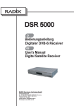
2.1 Top View
MOTOR#l
COUNTERCLOCKWlSS
PROPELLER
MOTOR#6
MOTOR#2
CLOCKWISE PROPElLER
MOTOR#3
COUNTERCLOCKWISE
PROPELLER
COUNTERCLOCKWISE
PROPELLER
MOTOR#4
CLOCKWISE PROPELLER
16
Turbo Ace CINEWING 6
2.4 Part Specification
Remarks
No.
Part
Specifications
QTY
Units
1
Chassis Cover
ABS Composite Material
1
Set
2
Arm
6
PCS
3
Skid Landing
1
Set
4
Motor
6
PCS
Special
5
Propeller
6
PCS
Special
6
PTZ
1
Set
7
ESC
6
PCS
Special
1
PCS
Special
8
Flight Control
System
High Strength
Carbon Fiber Tubing
Carbon Fiber
380KV
Brushless Motor
Carbon Propeller
Fiberglass I Carbon Fiber
Two-Dimensional Equilibrium
6S 40A Electronic Speed
Controller
DJI WOOKONG-M or Naza
Optional
18
Turbo Ace CINEWING 6
2.5 Technical Parameters
Width
Extended
Width
Diameter From Outer Edges of Motors
983mm
Diameter From Extended Propellers
1310 mm
Motors Center
Diameter From Center of Motor to Center
to Center
of Motor on Opposite Side
Height
Propeller
Bottom of Skid Landing to Top of Dome
Cover
3 x CW & 3 x CCW (1555 Props use 380kv
motors and 1765 use 290kv motors)
Battery
Weight
Flight Distance
Wind strength
15" or 17"
1 or 2 PCS
No battery, no gimbal
7lbs
Limited by Sight & the
±3mm
173mm
LiPo 6S 5300mAh 35C or lO,OOOmAh
Receiver/Transmitter
Flight Time
935mm
±3mm
±lOg
1-2 miles
2 x 6S 5300mAh Battery (1 0,600mAh total)
25 minutes
tolerance
Class 5
No wind hover
19
Turbo Ace CINEWING 6
CINEWING 6 SETUP
3.1 Unpacking the CINEWING 6
Remove all CINEWING 6 contents from the box. Do not pull on the transmitter
antenna to remove the transmitter out of the box, because you might damage the
antenna. Instead, pull on the neck strap to remove the unit out of the box.
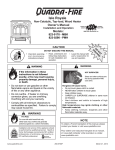
3.2 Mounting Propellers
Clockwise Counter-Clockwise
Top
View
Bottom
View
20
Turbo Ace CINEWING 6
A crucial step in preparing to mount your propellers (props) is to determine which
props are clockwise (CW) and which are counter-clockwise (CCW). The first step is
to make sure that you are looking at the top of the prop. Make sure that the side with
the bearing is facing the ground (Bottom side). Next, look at the part of the blade right
next to the center of the prop. The blade will have one edge higher than the other. The
higher edge is considered the leading edge of the blade. Looking to the blade on the
right side, if the leading edge is towards you (assuming that the prop is horizontally
oriented), then the prop will rotate clockwise. If the leading edge is facing away from
you, then the prop will rotate counter-clockwise. There are a total of 8 propellers in
your package. 3 of the propellers are counter-clock-wise (CCW) type propellers. The
other 3 propellers are marked as clock-wise (CW) type propellers. Each type of
propeller must be mounted on a specified motor on the CINEWING 6- please refer to
the diagram in Section 2.1 Top View of the CINEWING 6.
(1) Unscrew the screws and remove the propeller cover.
(2) Due to the precision needed to reduce vibration, the propellers are designed to fit
tightly on the motors. Insert each type of propeller to each specified motor
location. Motors 1 & 3 & 5 use counter-clock-wise propellers and motors 2 & 4 &
6 use clock-wise propellers. Please make sure that they match exactly (see top
view figure on Diagram and Parts section). Failure to mount the correct
propeller(s) will result in a crash. The propellers that come with the CINEWING 6
are custom enforced for stability and are stiffer and stronger than stock propellers
available in the market. Using alternative propellers may cause video vibration.
(3) It is very important to put some Loctite on the inside of each screw before
securing it to the propeller. Over tightening the screws may damage the motor
aluminum threads. Repeat this for all 6 propellers.
IMPORTANT: Every time you remove the propellers, you need to reapply some
Loctite and let it dry.
3.4 Battery Requirements & Installation
(1) Standard Battery: 6-S LiPo, 22.2V, 5300mAh, 35C, 2 PCS or one 10,000mAh
(2) Release the wide Velcro strap near the top cover.
NOTE: The center of gravity is best accomplished with the battery mounted on
the top cover.
(3) Do not plug in the main battery power to the CINEWING 6 at this time.
21
Turbo Ace CINEWING 6
ELECTRONICS SETUP & ADJUSTMENT
If you have purchased an RTF package (CINEWING 6 with transmitter), please
skip Sections 4.1 through 4.5, because all settings have been completed and your
CINEWING 6 and transmitter have been calibrated, paired, and test-flown as a set.
Unless you are familiar with the settings, any changes might override the factory's
settings and disable the aircraft, affecting its performance and flight reliability.
If you have purchased an ARF package (CINEWING 6 without transmitter) and
you have a Walkera or Walkera Devention transmitter, you can skip Section 4.1
and go directly to Section 4.2 for the Transmitter Calibration. In order for a flight
controller to work properly, your specific transmitter has to be calibrated to work with
each new CINEWING 6. Crashes will be imminent if you skip this one time
procedure to match a CINEWING 6 with a transmitter.
If you have purchased an ARF package (CINEWING 6 without transmitter) and
you are not using a Walkera or Futaba transmitter, you must complete Section 4.1
ESC Programming and Section 4.2 Transmitter Calibration. CINEWING 6 ESCs
were originally programmed to work with Walkera and Futaba transmitters. To use
the same ESCs on Spektrum, JR or other transmitters, the end user needs to reprogram
each ESC independently. Also, in order for a flight controller to work properly, your
specific transmitter has to be calibrated to work with each new CINEWING 6.
Crashes will be imminent if you skip these one-time procedures to match a
CINEWING 6 with a transmitter.
4.1 ESC Programming for Spektrum DX 8 Transmitter (Required
Setup For ARF)
Video Instruction:
How to calibrate the ESC for CINEWING 6:
https://www.dropbox.com/s/qwvt489g9j6zs7x/Calibration%20for%20Spektrum
%20ESCs.MP4
Please skip this ESC programming step if you have purchased an RTF unit, since all
ESCs have been re-programmed. If you purchased an ARF unit, please follow the
steps below very carefully. The procedure will only take a few minutes.
22
Turbo Ace CINEWING 6
(1)
IMPORTANT: Remove all6 propellers from the motors for safety.
(2)
Double check to make sure all ESC connectors are marked/labeled (#1
through #6, matching the connectors on the flight controller #1 through #6)
so that you will be able to keep track of the corresponding connectors when
you need to put them back later.
(3)
Disconnect all 6 ESC connectors from the W ooKong/NAZA flight controller
so they will not interfere with each other's programming.
(4)
Move the throttle stick all the way down. Now turn on the transmitter.
Disconnect X3 on the NAZA flight controller and plug it into AUX 1 on the
(5)
recetver.
(6)
Insert the #1 labeled ESC connectors into the receiver's throttle channel port
while watching for the correct polarity. Black/dark brown wires are usually
on the edge of the receiver. Please verify polarity in your receiver manual if
you are not using the stock receiver. (Make sure the Receiver and
Transmitter radio are bound)
(8)
Move the throttle stick all the way up.
Within 3 seconds, connect the battery to the CINEWING 6 battery plug (The
CINEWING 6 battery plug is still connected to all 6 ESCs but only one ESC
(9)
should be connected to the receiver at a time.)
When the ESC makes 1 beeping sound, immediately move the throttle stick
all the way down. The ESC will then make 2 beeping sounds (If you did not
(7)
hear the 1 beeping sound when entering programming mode or you did not
hear 2 beeping sounds after the ESC completed its programming, then you
need to move throttle all the way down and disconnect the battery from the
CINEWING 6 battery plug and repeat Steps (6) to (9) for the ESC. If you
did not experience any problems, then you have completed programming for
this ESC, which now retains the high and low end point data in its memory.
Disconnect the battery from the CINEWING 6's battery connector, then
disconnect the ESC connector from the receiver.
(10) Repeat Steps (6) to (9) for each ESC. Please make sure you have
programmed all 4 ESCs by starting with the #1 labeled ESC and finishing
with #6 labeled ESC. Your transmitter power should remain in the power on
position throughout the entire process of programming all 6 ESCs.
(11) After you have successfully re-programmed all 4 ESCs, unplug the battery
from the CINEWING 6 battery plug. Insert the 6 ESC connectors, labeled #1
through #6, back to corresponding M 1 through M6 ports on your
23
Turbo Ace CINEWING 6
WooKong/NAZA flight controller. The black/dark brown wire (-) for each
ESC connector is closest to the red NAZA label of the flight controller.
4.1 ESC Programming for Futaba 14SG Transmitter (Required
Setup For ARF)
Video Instruction:
How to calibrate the ESC for CINEWING 6:
https://www.dropbox.com/s/z09ojui7ptd4rxr/1. %20Futaba%20Esc%20Progra
ming.MP4
Please skip this ESC programming step if you have purchased an RTF unit, since all
the ESCs have been re-programmed. Please follow the steps below very carefully.
They will only take a few minutes.
(1) VERY IMPORTANT: Remove all6 propellers from the motors for safety.
(2)
Double check to make sure all ESC connectors are marked/labeled (#1
through #6 matching the connectors on the flight controller #1 through #6)
so that you will be able to keep track of the corresponding connectors when
you need to put them back later.
(3)
Disconnect all 6 ESC connectors from the NAZA flight controller so they
may not interfere with each other's programming.
(4)
Move the throttle stick all the way down. Now turn on the transmitter.
(5)
Disconnect X3 on the NAZA flight controller and plug into port 8 on the
receiver.
(6)
Turn on Futaba radio-7double tap "LNK"-7go to "Reverse"-7go to THR
and set it to "REV"
(7)
Insert one of the labeled ESC connectors into the receiver's throttle channel
(wow default port 3) port while watching for the correct polarity. Black/dark
brown wires are usually on the edge of the receiver. Please verify polarity in
your receiver manual if you are not using the stock receiver.
(8)
Move the throttle stick all the way up.
(9)
Within 3 seconds, connect the battery to the CINEWING 6's battery plug
(The CINEWING 6 battery plug is still connected to all 6 ESCs but only one
ESC should be connected to the receiver at a time).
(1 0) When the ESC makes 1 beeping sound, immediately move the throttle stick
all the way down. The ESC will then make 2 beeping sounds (If you did not
hear the 1 beeping sound when entering programming mode or you did not
24
Turbo Ace CINEWIN G 6
hear 2 beeping sounds after the ESC completed its programming, then you
need to move throttle all the way down, disconnect the battery from the
CINEWING 6 battery plug and repeat Steps (7) to (1 0) for the ESC. If you
did not experience any problems, then you have completed programming on
this ESC which now retains the high and low end point data in its memory.
Disconnect the battery from the CINEWING 6's battery connector then
disconnect the ESC connector from the receiver.
(11) Repeat this process for each ESC from Step (7) through Step (10). Please
make sure you have programmed all 6 ESCs by starting with the # 1 labeled
ESC and finishing with #6 labeled ESC. Your transmitter power should
remain in the power on position throughout the entire process of
programming all 6 ESCs.
(12) After you have successfully re-programmed all 6 ESCs, unplug the battery
from the CINEWING 6 battery plug.
(13) Now reverse the throttle back to normal on Futaba radio-7double tap
"LNK"-7go to "Reverse"-7go to THR and set it to "NORM"
(14) Insert the 6 ESC connectors, labeled #1 through #6 back to corresponding
M1 through M6 ports on your NAZA flight controller. The black/dark
brown wire (-) for each ESC connector is closest to the red NAZA label of
the flight controller.
4.2 Transmitter Calibration for Spektrum DX 8 Transmitter
(Required Setup For ARF)
Video Instruction:
1. How to set up fail safe for Spektrum transmitter:
https://www.dropbox.com/s/pw2nogpjubwaubj/3.%20Failsafe%20SPK.MP4
2. How to set up Spektrum transmitter calibration:
https://www.dropbox.com/s/z64exwcrnna634j6/4.%20TX%20Calibration%20
Settings%20SPK.MP4
3. How to fine tune Spektrum transmitter:
https://www .dropbox.com/s/8ybfe61 e6o8bxae/5. %20Fine%20Tune%20SPK.
MP4
4. How to set up the gain setting:
https://www .dropbox.com/s/2pkkn3ipc73tbwy/7. %20Gain%20Setup.MP4
25
Turbo Ace CINEWING 6
If you purchased your CINEWING 6 with a transmitter (RTF package) please skip
this section because we have already completed calibration. If you are using a
transmitter that has never been paired with your new CINEWING 6, you will need to
calibrate your transmitter to the CINEWING 6 flight controller using the following
procedure. Any change to the hexacopter or setting change to the transmitter might
require transmitter calibration.
(1)
VERY IMPORTANT: Remove all6 propellers from the motors for safety.
(2)
Tie down your CINEWING 6
Turn on your transmitter radio.
(3)
(4)
(5)
(6)
(7)
(8)
Connect battery to the CINEWING 6battery connector.
Connect the provided Programming USB Cable from .your PC computer's
USB port (XP or WIN? or WINS) to the Micro USB port on the
CINEWING 6communication port (on the LED side panel of the
CINEWING 6). (If the computer does not recognize the USB, the USB
driver is located in the provided 8GB USB flash drive)
Double click on the NAZAinstaller.exe, located in the provided 8GB USB
flash drive, and install the NAZA ASSISTANT SOFTWARE.
Double click on the application file named NAZA ASSISTANT
SOFTWARE. Wait for the program to start up.
Click MOUNTING Use to input the distance between GPS and Main Flight
Controller.
(9)
Click MOTOR MIXER
MIXER TYPE: Please select Hexa-rotor I and remember to click WRITE
after you update any settings (WRITE is #7 on top of FIGURE 4.2)
(10) Click TX CALI
26
Turbo Ace CINEWING 6
•
Directional Stick controls "E" (Elevator): Stick down and "E" slides left (tilts
back) & stick up and "E" slides right (tilts forward)
•
Directional Stick controls A (Aileron): Stick left and "A" slides left (roll left) &
stick right and "A" slides right (roll right).
After Calibration, place all sticks at the center which will turn all sliders green. At this
point click FINISH to end.
(14) STICKS MONITOR is not used at this time.
(15) CONTROL MODE SWITCH: (Please see Section 4.7 CINEWING 6
Wiring Connection Chart)
Setting the GPS Attitude and Attitude and Manual Mode on the Flap Switch
on Spektrum DX8 Transmitter
Setting the GPS, Attitude and Manual Mode on the Flap Switch on CINEWING 6:
(1) The NAZA Assistant screen should show a Control Mode Switch with GPS I
Fail Safe I A I Fail Safe I M. (The "GPS" represent the GPS Mode, the "A"
represent "Attitude Mode" and the "M" represent "Manual Mode"). You need
a 3 position switch for the Control Mode Switch. For example: When using
Spektrum DX8 and AR8000, the Control Mode Switch is assigned to the Flap
switch on the transmitter. This is done by connecting the Receiver's AUX1
channel to the Flight Controller's "U" channel (See FIGURE 4.2). Hold down
roller while turning on the Spektrum DX8-7scroll down to "Switch
Select"-?scroll down to "Flap" press roller-?change to "AUX 1" (If you
cannot find Flap in the list, you will need to change the model type to
"Airplane", in order for "Flap" to show up in the selection.
(2) Now you need to make sure when the Flap Switch is flipped forward (away
from you) the switch will change the flight controller to "GPS Mode." If the
Control Mode Switch (See FIGURE 4.2 bottom) slider is closer to "M" or "A",
then the Control Mode Switch slider is in the wrong position. To bring the
slider closer to "GPS." Tum on transmitter-?Click on roller-?scroll down to
"Servo Setup"-?scroll to "travel" and click on roller, which will have a
flashing box-?scroll to "Reverse", click the roller to make the flashing box
become solid -?scroll down to "Throttle" and change to "AUX 1"-?scroll
down to the NOR and REV box-? click the roller to reverse the AUX 1
channel (which is now set to your Flap Switch setting). This change will bring
the Control Mode Switch slider closer to "GPS."
28
Turbo Ace CINEWING 6
(3) How to set up fail safe for Spektrum transmitter, please following the
instruction in the video link below
https://www.dropbox.com/s/pw2nogpjubwaubj/3.%20Failsafe%20SPK.MP4
(4) Move your Flap Switch to the middle position to set the sub trim for the
middle position first. If the "A" segment turns blue please skip to Step (6).
(5) If the "A" segment does not tum blue, Click on roller-7scroll down to "Servo
Setup"-7scroll to "travel" and click on roller, which will have a flashing
box-7scroll to "subtrim", click the roller to make the flashing box become
solid -7scroll down to "Throttle" and change to "AUX 1"-7scroll down to the
0 and adjust the until "A" segment turns blue.
(6) Flip the Flap Switch forward (away from you). If the "GPS" segment turns
blue then skip to Step (8).
(7) If the "GPS" segment does not turn blue, Click on roller-7scroll down to
"Servo Setup"-7scroll to "travel" and click on roller, which will have a
flashing box-7 scroll down to "Throttle" and change to "AUX 1"-7scroll
down to the 100% and adjust the value until "GPS" segment turns blue.
(8) Flip the Flap Switch backward (towards you). If the "M" segment turns blue
then skip to Section 4.2.11.
(9) If the "M" segment does not tum blue, Click on roller-7scroll down to "Servo
Setup"-7scroll to "travel" and click on roller, which will have a flashing
box-7 scroll down to "Throttle" and change to "AUX 1"-7scroll down to the
100% and adjust the value until "M" segment turns blue. Make sure to test
the failsafe by tum off your transmitter and the slider should move to failsafe
and turn blue and the throttle will go to midpoint on the screen.
AUTOPILOT
(1) BASIC PARAMETERS: Recommend setting for Pitch set to 130%, Roll set
to 120%, Yaw set to 90% and Vertical set to 120% and ATTITUDE GAIN is
Pitch set to 100% and Roll set to 100%. REMOTE ADJUST is set to INH.
Basic Gain and Attitude Gain should never set to lower than 100%, otherwise
crash might result.
(2) ENHANCED FAILED-SAFE METHODS. (GPS module is required).
Recommended setting for enhanced failed-safe methods is to set it to
GO-HOME and LANDING. (Please refer to DJI NAZA User Manual's page
21 for enhanced failsafe methods).
(3) INTELLIGENT ORIENTATION CONTROL (IOC): (GPS module is
required). Check the box next to "3. Intelligent Orientation Control." If GPS is
29
Turbo Ace CINEWING 6
installed, the settings for Spektrum DX 8 and AR8000 as follows. Assign the
intelligent orientation control to the F MODE Switch on the transmitter,
connecting the Receiver's Gear channel to the Flight Controller's "X2"
channel (See FIGURE 4.2). Hold the roller while turning on the Spektrum
DX8~scroll
"Inh"~scroll
down to "Switch
Select"~scroll
to "Gear" change to
to "F MODE" change to "Gear."
(4) Now you need to make sure when the F MODE Switch is flipped forward
(toward the ground) the switch will change the Intelligent Orientation Control
to "Off." If the slider is closer to "Course Lock" or "Home Lock", then the
Intelligent Orientation Control Switch slider is in the wrong position. To bring
the slider closer to "Off." Turn on
transmitter~click
on
roller~scroll
to
"Servo
Setup"~scroll
to "Travel", click on roller, which will have a flashing
box~
scroll down to
"Reverse"~scroll
"Gear"~ scroll
down to "Throttle" and change to
down to NOR & REV to reverse your Channel Gear setting to
"REV" (which is now set to your F MODE Switch setting). This change will
bring the Intelligent Orientation Control Switch slider closer to "Off."
(5) Move your F MODE Switch to the middle position to set the midpoints for the
middle position first. If the "Course Lock" segment turns blue please skip to
Step (4).
(6) If the "Course Lock" segment does not turn blue, click on
"Servo
Setup"~scroll
to "Travel" and change to
"Throttle" and change it to
"Gear"~scroll
down to
roller~scroll
"subtrim"~scroll
"O"~adjust
to
down to
the value until
"Course Lock" segment turns blue.
(7) Flip the F MODE Switch forward (toward the ground). If the "Off' segment
turns blue then skip to Step (6).
(8) If the "Off' segment does not turn blue, click on
Setup"~scroll
"Gear"~ scroll
to
"Travel"~scroll
roller~scroll
to "Servo
down to "Throttle" and change it to
down and adjust the value until "Off' segment turns blue.
(9) Flip the F MODE Switch backward (towards the sky). If the "Home Lock"
segment turns blue.
(10) If the "Home Lock" segment does not turn blue, click on
"Servo
Setup"~scroll
"Gear"~scroll
to
"Travel"~ scroll
roller~ scroll
to
down to "Throttle" and change it to
down and adjust the value until "Home Lock" segment turns
blue.
Home Lock only activates while CINEWING 6 is about 30 feet (10 meters) away
from the home position (Takeoff Position). To change the Home Lock position during
30
Turbo Ace CINEWING 6
flight, please refer to the DJI User Manual for detailed descriptions and functions of
HOME LOCK and COURSE LOCK.
4.2 Transmitter Calibration for Futaba 14SG Transmitter
(Required Setup For ARF)
Video Instruction:
1. How to connect Futaba RX and setup Futaba TX:
https://www.dropbox.com/s/vztqrvhplxq3h80/2.%20Futaba%20RX%20Setup.MP4
2. How to set up fail safe for Futaba transmitter:
https://www.dropbox.com/s/63nlylwy4lnvl7y/6.%20Futaba%20Control%20Mode%2
0Failsafe.MP4
3. How to set up Futaba transmitter calibration:
https://www.dropbox.com/s/wws2w6pyba91ra9/5. %20Futaba%20TX%20Callibration
.MP4
4. How to set up the gain setting:
https://www .dropbox.corn/s/2pkkn3ipc73tbwy/7. %20Gain%20Setup.MP4
5. How to set up advanced setting:
https://www.dropbox.com/s/76vv670q6jb99lu/8.%20Advanced%20Setup.MP4
6. How to set up the voltage setting:
https://www.dropbox.com/s/clsrg9ixxp8b2xn/9. %20Voltage%20Setup.MP4
If you have purchased your CINEWING 6 with a transmitter (RTF package) please
skip this section because we have already completed calibration. If you are using a
transmitter that has never been paired with your new CINEWING 6, you will need to
calibrate your transmitter to the CINEWING 6 flight controller using the following
procedure. Any change to the hexacopter or setting change to the transmitter may
require transmitter calibration.
(1)
VERY IMPORT ANT: Remove all 6 propellers from the motors for safety.
(2)
Tie down your CINEWING 6.
(3)
Tum on your transmitter radio.
(4)
Connect battery to the CINEWING 6 battery connector.
(5)
Connect the provided Programming USB Cable from your PC computer's
USB port (XP or WIN7 or WINS) to the Micro USB port on the
CINEWING 6 communication port (on the LED side panel of the
CINEWING 6). (If the computer does not recognize the USB, the USB
driver is located in the provided 8GB USB flash drive)
31
Turbo Ace CINEWING 6
direction, click the NORM or REV to reverse the direction of the slider
movement.
•
Throttle/Yaw Stick controls "T" (Throttle): Stick down and "T" slides left
(reduce power) & stick up and "T" slides right (increase power).
•
Throttle/Yaw Stick controls "R" (Rudder): Stick left and "R" slides left (nose to
the left) & stick right and "R" slides right (nose to the right).
•
Directional Stick controls "E" (Elevator): Stick down and "E" slides left (tilts
leans back) & stick up and "E" slides right (tilts forward)
•
Directional Stick controls A (Aileron): Stick left and "A" slides left (leans left)
& stick right and "A" slides right (leans right).
After Calibration, place all sticks in the center, which will tum all sliders green. At
this point, click FINISH to end.
(14)
STICKS MONITOR is not used at this time.
(15) CONTROL MODE SWITCH: (Please see Section 4.8 CINEWING 6
Wiring Connection Chart)
Setting the GPS Attitude, Attitude and Manual Mode on the SB Switch on
Futaba 14SG Transmitter:
Setting the GPS, Attitude and Manual Mode on the Mix Switch on CINEWING 6:
(1) The NAZA Assistant screen should show a Control Mode Switch with GPS I
Fail Safe I A I Fail Safe I M. (The "GPS" represents the GPS Mode, the "A"
represents "Attitude Mode" and the "M" represents "Manual Mode"). You
need a 3-position switch for the Control Mode Switch. For example: When
using Futaba 14SG and R7008SB, the Control Mode Switch is assigned to the
SB switch on the transmitter. This is done by connecting the Receiver's 5
channel to the Flight Controller's "U" channel (See FIGURE 4.2). Tum on the
Futaba 14SG, double tap "LNK"-7scroll down to "Function" press
"RTN"-7scroll down to channel5-7Change CTRL to "SB."
(2) Now you need to make sure that when the SB Switch is flipped forward (away
from you), the switch will change the flight controller to "GPS Mode." If the
Control Mode Switch (See FIGURE 4.2 bottom) slider is closer to "M" or "A",
then the Control Mode Switch slider is in the wrong position. To bring the
slider closer to "GPS", double tap "LNK"-7scroll down to "REVERSE"
33
Turbo Ace CINEWING 6
7scroll down to Channel57tap "RTN" and reverse your ChannelS setting to
"REV" (which is now set to your SB Switch setting). This change will bring
the Control Mode Switch slider closer to "GPS."
(3) Transmitter can be turned on and off to bind and re-bound, which will make
fail safe testing easier. To setup Fail-Safe, double tap "LNK"7scroll down to
"END POINT"7scroll down to Channel 57adjust travel value until the
failsafe turn blue7double tap "LNK"7scroll down to "FAIL SAFE"7scroll
down to Channel57scroll to F/S and change to "F/S"7scroll to "POS," hold
"RTN" for 1 second, and it will set the value for failsafe automatically.
(4) Move your SB Switch to the middle position to set the sub trim for the middle
position first. If the "A" segment turns blue, please skip to Step (6).
(5) If the "A" segment does not tum blue, double tap "LNK"7scroll down to
"SUB-TRIM"-7 scroll down to Channel 5 7change the value until "A"
segment turns blue.
(6) Flip the SB Switch forward (away from you). If the "GPS" segment turns blue,
then skip to Step (8).
(7) If the "GPS" segment does not turn blue, double tap "LNK"7scroll down to
"ENDPOINT"7scroll down to Channel 57find the travel value and tap
"RTN"7value will flash and you can change the value until "GPS" segment
turns blue.
(8) Flip the SB Switch backward (towards you). If the "M" segment turns blue,
then skip to Section 4.2.11.
(9) If the "M" segment does not turn blue, double tap "LNK"7scroll down to
"ENDPOINT"7scroll down to Channel 57 find the travel value and tap
"RTN"7value will flash and you can change the value until "M" segment
turns blue. Make sure to test the failsafe by turning off your transmitter. The
slider should move to failsafe and turn blue.
AUTOPILOT
(1) BASIC PARAMETERS: Recommended settings are Pitch set to 130%, Roll
set to 120%, Yaw set to 90%, and Vertical set to 120%. ATTITUDE GAIN is
Pitch set to 100% and Roll set to 100%. REMOTE ADJUST is set to INH.
Basic Gain and Attitude Gain should never be set to lower than 100%,
otherwise crashes may result.
(2) ENHANCED FAILED-SAFE METHODS. (GPS module is required).
Recommended settings for enhanced failed-safe methods is to set to
34
Turbo Ace CINEWING 6
GO-HOME and LANDING (Please refer to DJI NAZA User Manual's page
21 for enhanced failed-safe methods).
(3) INTELLIGENT ORIENTATION CONTROL (IOC): (GPS module is
required). Check the box next to "3. Intelligent Orientation Control." IfGPS is
installed, the settings for Futaba 14SG and R7008SB are as follows: Assign
the intelligent orientation control to the SE Switch on the transmitter,
connecting the Receiver's 6 channel to the Flight Controller's "X2" channel
(See FIGURE 4.2). Turn on the Futaba 14SG, double tap "LNK"7scroll
down to "Function" press "RTN"7scroll down to channel 67Change CTRL
to "SE."
(4) Now you need to make sure that when the SE Switch is flipped forward
(toward the ground) the switch will change the Intelligent Orientation Control
to "Off." If the slider is closer to "Course Lock" or "Home Lock", then the
Intelligent Orientation Control Switch slider is in the wrong position. To bring
the slider closer to "Off',
double tap "LNK"-?scroll down to "REVERSE" 7scroll down to Channel
67tap "RTN" and reverse your Channel6 setting to "REV" (which is now set
to your SE Switch setting). This change will bring the Intelligent Orientation
Control Switch slider closer to "Off."
(5) Move your SE Switch to the middle position to set the midpoints for the
middle position first. If the "Course Lock" segment turns blue, please skip to
Step (4).
(6) If the "Course Lock" segment does not tum blue, double tap "LNK"7scroll
down to "SUB TRIM"7scroll down to Channel 67adjust the value until
"Course Lock" segment turns blue.
(7) Flip the SE Switch forward (toward the ground). If the "Off' segment turns
blue, then skip to Step (6).
(8) If the "Off' segment does not tum blue, double tap "LNK"7scroll down to
"END Point"7scroll down to Channel 67find the travel value and tap
"RTN"7adjust the value until "Off' segment turns blue.
(9) Flip the SE Switch backward (towards the sky) if the "Home Lock" segment
turns blue.
(10) If the "Home Lock" segment does not tum blue, double tap "LNK"7scroll
down to "END Point"7scroll down to Channel 67find the travel value and
tap "RTN"7adjust the value until "Home Lock" segment turns blue.
Home Lock only activates while CINEWING 6 is at about 30 feet (10 meters) away
from the home position (Takeoff Position). To change the Home Lock position during
35
Turbo Ace CINEWING 6
flight, please refer to the DJI User Manual for detailed descriptions and functions of
HOME LOCK and COURSE LOCK.
4.3 Transmitter & Receiver Compatibility Table (For ARF Only)
The CINEWING 6 prefers a 2.4GHz system, but also supports 35MHz, 40MHz, and
72MHz.
No.
1
2
3
4
5
6
7
8
9
10
Brand
Walkera
Spektrum
JR
JR
WFLY
Futaba
Futaba
Futaba
Sanwa
Hi-TEC
Transmitter
DEVENTION 10
DX8
DSX7
9XII
FT06-C
FF9
6EX
10C
RD8000
Eclipse?
Receiver
RX1002
AR8000
RD721
FRP06
R149DP
R146iP
92777
FRP06
4.4 Receiver, Flight Controller & Auto-stabilization Setup for
Spektrum DX8
FIGURE 4.4
36
Turbo Ace CINEWING 6
(1)
Connect Channel #T w1re from the flight controller to the THROTTLE
channel of the receiver. Watch for polarity.
(2)
Connect Channel #E wire from the flight controller to the ELEV channel of
the receiver.
(3)
Connect Channel #A wire from the flight controller to the AILE channel of the
receiver.
(4)
Connect Channel #R wire from the flight controller to the RUDDER channel
of the receiver.
(5)
Connect Channel #U wire from the flight controller to the AUX 1 channel of
the receiver.
(6)
Connect Gyrox Brushless gimbal tilt control cable to the AUX 3 channel of
the receiver.
(7)
Connect Channel #X2 wire from the flight controller to the GEAR channel of
the receiver.
(8) Connect Channel #X3 wire from the flight controller to the LED Versatile Unit
(PMU).
Setting up CINEWING 6 to ensure a smooth flight with GPS or Attitude mode
To ensure the smooth flight of your Turbo Ace CINEWING 6, please make sure that
you setup and fly the CINEWING 6 in GPS or Attitude mode. In order for GPS or
Attitude mode to function, first it is important to make sure the flap switch on your
radio is all the way forward. Please refer to Section 4.2 Transmitter Calibration. If you
own a Spektrum radio such as the DX8, you will need to reverse the gear channel in
your radio so that when you flip the gear switch forward, it enables GPS or Attitude
Mode. If you are experiencing difficulties in handling the aircraft, it may be because it
is not in GPS or Attitude Mode.
You may skip the following setup instructions if you have purchased the Turbo Ace
CINEWING 6 with a transmitter radio, as we have already completed all the setup for
you. If you have purchased a CINEWING 6 without a radio, please see the following
to make sure your radio is setup correctly.
Setting up and checking Turbo Ace CINEWING 6 flight mode for GPS or
Attitude Mode.
Plug in a 3 pin cable connector to the "INPUT" channel U of the NAZA flight
controller. Connect the other end of the cable to the AUX 1 output on your receiver
37
Turbo Ace CINEWING 6
with the brown wire closest to the edge of the receiver casing (If you have a receiver
other than a Walkera, Devention or Spektrum, please check your receiver manual for
polarity).
CINEWING 6 with GPS module (Assign AUX 1 to 3 position toggle switch, WOW
default Flap switch for Spektrum DX 8):
Hold down roller while turning on the Spektrum DX8-7scroll down to "Switch
Select"-?scroll down to "Flap" press roller-?change to "AUX 1" (If you cannot find
Flap in the list, you will need to change the model type to "Airplane" in order for
"Flap" to show up in the selection. This means that every time the Flap switch is
flipped forward on your radio, it will toggle the AUX 1 output of the receiver and tell
the controller to perform GPS Mode. For Spektrum radio, you will need to change
from normal to reverse on the AUX 1 channel in your radio so that when you flip the
Flap switch forward on the radio, you are activating the GPS mode. The reason to
setup the radio this way is to ensure everything is in the correct default mode when all
the switches on your radio are all the way forward (away from you). You can use the
NAZA Assistant Software to double check the Flap switch operation after you have
completed the above setup.
Turn on your transmitter radio (Warning: Always tie down the CINEWING 6 and
remove all propellers when you perform any setting changes to the transmitter or
NAZA Assistant Software. Failure to do so may cause serious issues, as the
CINEWING 6 motor may start up if an incorrect value is entered). Connect the
provided Programming USB-to-Micro USB cable from your PC computer's USB port
(XP or WIN7) to Micro USB port on the CINEWING 6 communication port (on the
LED side panel of the CINEWING 6). Please connect this cable after the transmitter
is bound to the receiver.
Double click on NaZainstaller.exe, located in the provided 8GB USB flash drive, to
install the NAZA ASSISTANT SOFTWARE
After the complete installation of the NAZA ASSISTANT SOFTWARE, double click
on the application file named NAZA ASSISTANT SOFTWARE. Wait for the
program to start up.
Select the TX Calibration tab at the left column of the screen.
CINEWING 6 with GPS
38
Turbo Ace CINEWIN G 6
You will see the 5 mode tabs: GPS, Fail Safe, A, Fail Safe, M. When you flip the Flap
switch on your radio, you will see the selection flipping between GPS and A and M.
When the Flap switch is flipped forward, you will see GPS is selected, which enables
GPS Mode. The GPS Mode is the mode you should be using to fly your CINEWING
6. M mode has no stabilization and will make it very difficult to operate the aircraft.
IMPORTANT: Make sure that the Flap switch on your radio is in the
forward/middle position before taking off and during the entire flight. (Please refer to
section 4.2 Transmitter Calibration if GPS and A and M mode do not turn blue on the
screen when you flip the Flap switch).
4.4 Receiver, Flight Controller & Auto-stabilization Setup for
Futaba 14SG
FIGURE 4.4
(1)
Connect Channel #A wire from the flight controller to the channel 1 of the
receiver.
(2)
Connect Channel #E wire from the flight controller to the channel 2 of the
receiver.
(3)
Connect Channel #T wire from the flight controller to the channel 3 of the
receiver. Watch for polarity.
(4)
Connect Channel #R wire from the flight controller to the channel 4 of the
receiver.
(5)
Connect Channel #U wire from the flight controller to the channel 5 of the
receiver.
(6)
Connect Channel #X2 wire from the flight controller to the channel 6 of the
receiver.
39
Turbo Ace CINEWING 6
(7)
Connect Gyrox Brushless gimbal tilt control cable to the channel 7 of the
receiver.
(8)
Connect Channel #X3 wire from the flight controller to the LED Versatile
Unit (PMU).
Setting up CINEWING 6 to ensure a smooth flight with GPS or Attitude mode
To ensure the smooth flight of your Turbo Ace CINEWING 6, please make sure that
you setup and fly the CINEWING 6 in GPS or Attitude mode. In order for GPS or
Attitude mode to function, first it is important to make sure the mix switch on your
radio is all the way forward. Please refer to Section 4.2 Transmitter Calibration. If you
are experiencing difficulties in handling the aircraft, it may be because it is not in GPS
or Attitude Mode.
You may skip the following setup instructions if you have purchased the Turbo Ace
CINEWING 6 with a transmitter radio, as we have already completed all the setup for
you. If you have purchased a CINEWING 6 without a radio, please see the following
to make sure your radio is setup correctly.
Setting up and checking Turbo Ace CINEWING 6 flight mode for GPS or
Attitude Mode.
Plug in a 3 pin cable connector to the "INPUT" channel U of the NAZA flight
controller. Connect the other end of the cable to the Channel 5 output on your receiver
with the brown wire closest to the edge of the receiver casing (If you have a receiver
other than a W alkera, Devention or Spektrum, please check your receiver manual for
polarity).
CINEWING 6 with GPS module (Assign Channel 5 to 3 position toggle switch,
WOW default SB switch for Futaba 14SG):
Turn on the Futaba 14SG, double tap "LNK''-7scroll down to "Function" press
"RTN"-7scroll down to channel 5-?Change CTRL to "SB." This means that every
time the SB switch is flipped forward on your radio, it will toggle the Channel 5
output of the receiver and tell the controller to perform GPS Mode. For Futaba radio,
you might need to change from normal to reverse on the AUX 1 channel in your radio
so that when you flip the SB switch forward on the radio, you are activating the GPS
mode. The reason to setup the radio this way is to ensure everything is in the correct
default mode when all the switches on your radio are all the way forward (away from
40
Turbo Ace CINEWING 6
you). You can use the NAZA Assistant Software to double check the SB switch
operation after you have completed the above setup.
Turn on your transmitter radio (Warning: Always tie down the CINEWING 6 and
remove all propellers when you perform any setting changes to the transmitter or
NAZA Assistant Software. Failure to do so may cause serious issues, as the
CINEWING 6 motor may start up if an incorrect value is entered). Connect the
provided Programming USB-to-Micro USB cable from your PC computer's USB port
(XP or WIN7) to Micro USB port on the CINEWING 6 communication port (on the
LED side panel of the CINEWING 6). Please connect this cable after the transmitter
is bound to the receiver.
Double click on NaZainstaller.exe, located in the provided 8GB USB flash drive, to
install the NAZA ASSISTANT SOFTWARE.
After complete installation ofthe NAZA ASSISTANT SOFTWARE, double click on
the application file named NAZA ASSISTANT SOFTWARE. Wait for the program
to start up.
Select the TX Calibration tab at the left column of the screen.
CINEWING 6 with GPS
You will see the 5 mode tabs: GPS, Fail Safe, A, Fail Safe, M. When you flip the SB
switch on your radio, you will see the selection flipping between GPS and A and M.
When the SB switch is flipped forward, you will see GPS is selected, which enables
GPS Mode. The GPS Mode is the mode you should be using to fly your CINEWING
6. M mode has no stabilization and will make it very difficult to operate the aircraft.
IMPORT ANT: Make sure that the SB switch on your radio is in the forward/middle
position before taking off and during the entire flight (Please refer to section 4.2
Transmitter Calibration if GPS and A and M mode do not turn blue on the screen
when you flip the Flap switch).
4.5 Transmitter Settings (For ARF Only)
(1) Aircraft Mode: Fixed-wing airplane mode. Do not use helicopter mode.
(2) Rudder: 0% to 100% With No Mixing
(3) Curve: Channell, 2, 3 & 4 all set to zero
41
Turbo Ace CINEWING 6
(4) Gyro: Fine tune to maximize stability
(5) Move both the throttle stick and throttle trim by looking at the LCD screen to the
lowest position- Very important, otherwise motors will not start
(6) Aircraft Mode: Fixed-wing
(7) Rudder: 0% to 100% With No Mixing
(8) Use transmitter rudder trim to adjust heading (yaw)
(9) All channels are set to NORMAL for Walkera and Spektrum radios (Except Gear
Channel & AUX 1)
(10) For added stability on the CINEWING 6, you may choose to set the dual rate to
55%
Please double check all settings, tie the CINEWING 6 down to a bench, and test fly it
to check the settings. Some transmitters use random bind, which means you have to
plug in the battery to the CINEWING 6 within 2-3 seconds after the radio is turned
on. Please observe the LED light located at the back of the CINEWING 6 GPS
Module (Please refer to 5.3 LED light description). Fixed ID Bind is the TURBO
ACE default binding setting for the CINEWING 6 RTF unit (Please refer to the
FIXED ID BIND section). Most receivers flash before binding and remain solid after
binding, so please make sure your receiver has properly been bound to your
transmitter. Do not launch the CINEWING 6 on its maiden flight until all operations
are confirmed as normal, especially after shipping. Tie it down to a bench for a
preflight check. Failure to do so may cause serious damage to the CINEWING 6
and/or people around it. Factories and dealers will not be liable for any damages from
the operation of this aircraft.
4.6 Transmitter Flight Control & Gain Adjustments (For ARF
Only)
We do not recommend that any inexperienced users adjust the flight control or Gain
values using the DJI NAZA Assistant software. It is a steep learning curve for these
adjustments, which we have already fme-tuned and completed for you. Improper
settings may cause the CINEWING 6 to lose control and may result in serious
damage. If the original factory settings are altered in any way, with the exception of
transmitter calibration adjustments for ARF packages, it will automatically void the
24-hour "No Dead on Arrival" guarantee. Dead on arrival returns are strictly checked
for setting changes and tampering. Although knowledge can be acquired over time,
the CINEWING 6 flight controller adjustments are sophisticated and complicated. Do
42
Turbo Ace CINEWING 6
not attempt to change these settings until you are familiar with the setup. Please go to
online forums to learn about the flight control settings, as we do not provide any
technical support for these settings.
When you have purchased the Ready-to-Fly unit, there are 3 control modes that we
have setup on your flight controller and transmitter: GPS and ATTITUDE and
MANUAL. GPS Mode has the best auto stabilization and ability to perform GPS
Lock, making the aircraft very easy to fly. This mode is appropriate for videographic
and photographic applications. Attitude Mode has some auto stabilization and ability
to perform attitude hold and makes the aircraft easier to fly, which is also suitable for
videographic and photographic applications. Manual Mode is suited for experienced
pilots, as it allows more manual control in adverse. Do not switch to the MANUAL
mode if you are a beginner.
CINEWING 6 with GPS: The three modes can be switched during flight by toggling
the Flap switch on top of your radio. For the Ready-to-Fly CINEWING 6, we have set
this switch on your radio to GPS MODE when toggled forward, ATTITUDE MODE
when toggled to the middle, and MANUAL MODE when toggled backward. Before
takeoff, please make sure all front panel switches on your transmitter are flipped
forward and all switches such as the flight mode/hold switches on the side panel are
pushed down.
The basic gain and attitude gain values of the CINEWING 6 can be adjusted in the
AUTOPILOT section when you run the DJI NAZA ASSIST ANT SOFTWARE. The
default settings are BASIC GAIN Pitch set to 130%, Roll set to 120%, Yaw set to
90% and Vertical set to 120% and ATTITUDE GAIN Pitch set to 100% and Roll set
to 100% (Warning: BASIC GAIN should never be set lower than 90%). Again, it is
very important to remember to tie down the aircraft and remove all the propellers
when you are programming the fight controller with the supplied Programming
USB-MicroUSB cable. Failure to do so may cause accidental motor start up with
incorrect values entered and may result in serious injury. Always remember to tie
down the CINEWING 6 to a bench for test flights after you have changed any settings
(If the motor does not spin while performing the CSC, please re-calibrate/perform the
Command Sticks Calibration).
4. 7 GPS Calibration
GPS Calibration is required, if
43
Turbo Ace CINEWING 6
•
New WooKong-M or Naza is re-installed
•
GPS Module is repositioned
•
Any electronic devices are added/removed/repositioned (main controller, servo,
batteries, etc)
•
CINEWING 6 does NOT fly straight
(Please refer to WooKong-M/Naza User Manual section "Digital Compass
Calibration" for more details)
GPS Calibration procedure:
(1) (TURBO ACE default settings assign the control mode switch to mix switch on
Devo 10). Flip the control mode switch back and forth from "Manual mode" to "GPS
mode" 10 times, and the LED indicator (located behind the GPS) will turn a constant
blue- this indicates that you have entered calibration mode. Before continuing, make
sure the switch's starting position is in Manual Mode, and the ending position is in
GPS mode [***Manual mode is when the switch is flipped backward (toward pilot),
and GPS mode is when the switch is flipped forward (away from pilot)].
(2) Calibration in horizontal: Rotate the copter with the horizontal surface until the
LED turns a constant green, indicating completion of horizontal calibration.
(3) Calibration in vertical: while the LED is a constant green, hold your copter
vertically with the nose pointing down to the ground and rotate it along with the
vertical axis, until the green LED turns off, which indicates completion of vertical
calibration.
(4) After completion of the horizontal and vertical calibration, the LED will show
whether the calibration has been successful or not.
•
If LED turns white for 3 seconds, calibration was successful, and it will exit
calibration mode automatically.
•
If LED blinks red, the calibration failed. Please start the GPS calibration
again, starting from Step (1).
4.8 CINEWING 6 Wiring Connection Chart for Spektrum DX 8 &
AR8000
6 withGPS
DX8&
module
AR8000
NAZA
TX Setting
Gimbal
AR8000
FC
Output
Servo
ELEV
E
CINEWING6
44
Turbo Ace CINEWING 6
AILE
A
THRO
T
RUDD
R
AUX 17Flap
u
AUX1
AUX3
sw
GPS- ATTITUDE MODE- MANUAL
AUX3
TILT CONTROL FOR GIMBAL
OFF-COURSELOCK-HOMELOCK
Gear7F.Mod
X2
Gear
BATT
TELEMETRY (OPTIONAL)
4.8 CINEWING 6 Wiring Connection Chart for Futaba 14SG &
R7008SB
6 with GPS
14SG&
module
R7008SB
NAZA
TX Setting
Gimbal
R7008SB
FC
Output
Servo
1
A
2
E
3
T
4
R
5
u
SB
6
X2
SE
GPS- ATTITUDE MODE- MANUAL
OFF - COURSE LOCK- HOME LOCK
RD
TILT CONTROL FOR GIMBAL
7
BATT
CINEWING6
TELEMETRY (OPTIONAL)
4.9 Control Mode Comparison
GPS Mode
Command Stick
Meaning
Multi attitude control; Stick center
position for 0° attitude, its endpoint is
35°
Command
Linearity
Stick Released
Atti. Mode
Manual Mode
Max angular velocity is 150°/s.
No attitude angle limitation
and vertical velocity locking
Yes
Position Lock
when GPS signal is
Only attitude
stabilizing
NOT recommended to release
stick in any situation
45
Turbo Ace CINEWING 6
sufficient
Altitude Lock
Maintaining altitude lock is best above
After 1Os when
GPS Lost
GPS signal lost,
system engage
Attitude Mode
Safety
NO altitude lock
lm from ground
Only attitude
stabilizing without
position lock
Attitude & speed mixture control
NOT recommended to be used
ensures stability
in any situation
TESTING & OPERATIONS
5.1 Tie-Down Flight Test
(1) Tie down all six arms (not the skids) of the CINEWING 6 to a heavy fixture such
as a table or a work bench. Make sure there is plenty of space around the aircraft.
If you have a random binding transmitter such as the Devention 10, please make
sure there are no other similar radios nearby during the process of binding.
I
i .
(2) Prior to initiating your CINEWING 6, make sure it is on a water level surface
and do not move the CINEWING 6 before takeoff or during the binding process.
Failure to do so will result in miscalculations of the 3-Axis gyro compensation,
and the CINEWING 6 will not be able to operate properly.
46
Turbo Ace CINEWING 6
(3) Make sure your battery is fully charged using a battery meter (should read about
4.1 V to 4.2V per cell on all 6 cells). Plug in the battery connector to the power
input connector from the chassis. Do not run any LiPo batteries below 3.67V per
cell without load, otherwise the battery will be permanently damaged.
(4) After 2 seconds of initialization, the CINEWING 6 will issue 5 consecutive beep
tones.
(5) Place your transmitter flat on a table in front of you with the joystick facing up.
Make sure all switches above the two control sticks on the transmitter are pushed
forward and away from you and the two switches at the very top of the
transmitter side panel are pushed down towards the table. Move the throttle stick
(left stick) to the lowest position towards you. At this time, you do not need to
move the directional stick (right stick), which is spring loaded and will always
return to the middle position when released). Now you can tum your transmitter
"ON."
(6) Wait another six seconds for 5 consecutive beep tones from the CINEWING 6,
which indicate that binding between the receiver and the transmitter is complete.
Before moving any controls on the transmitter, it's always good practice to look
for the solid red LED light on the receiver to confirm that binding is complete.
(7) Stay at a safe distance and execute the combination stick command (CSC) to
start the motor.
(8) Make sure that the propellers of Motors #1, #3, #5 are rotating in a CCW
(counter clockwise) direction and the propellers of Motors #2, #4, #6 are rotating
in a CW (clockwise) direction. As you increase throttle, the propellers should
speed up and vice versa.
(9) Moving the rudder stick (which also controls the throttle) to the right should
decelerate CCW propellers (Motors #1, #3, #5), thereby decreasing CCW torque
so the aircraft turns CW. Moving the rudder to the left should decelerate CW
propellers (Motors #2, #4, #6), thereby decreasing CW torque so the aircraft
turns CCW.
(10) Moving the directional stick to the top should decelerate the three front
propellers (Motors # 1, #2, #6) and moving the directional stick to the bottom
should decelerate the back propellers (Motors #3, #4, #5). Moving the directional
stick to the left should decelerate the left propellers (Motors #2, #3) and moving
47
Turbo Ace CINEWING 6
the directional stick to the right should decelerate the right propellers (Motors #5,
#6).
(11) Move the throttle stick to the lowest position and the propeller should come to a
stop. Unplug the battery plug before turning the transmitter off.
(12) Repeat above Steps (2) to (11) twice more so that you complete 3 rounds of 8 to
10 minute tie-down flights.
5.2 Actual Flight Test & Training
(1) Pick a calm day or find a large empty indoor space. Keep all people and pets
away from the flight test area and place the CINEWING 6 on a level surface.
(2) Repeat Steps (2) through (11) under Section 5.1
(3) If you fly the CINEWING 6 too close to the ground, the wash (deflected air)
coming back up from the ground may cause significant flight instability. As with
all propeller driven systems, you should try to keep larger aircraft at least 3 to 4
feet from the ground and avoid flying in a small room, which deflects air current.
Before takeoff, you may also notice some vibration of the aircraft caused by auto
stabilization from the deflected air. Once the aircraft lifts away from the ground,
it will stabilize.
(4) If you are a beginner pilot, we highly recommend that you purchase a simulator
training package or a training quad such as the Walkera Ladybird or Walkera QR
X350. Even though the CINEWING 6 is equipped with easy-to-fly auto
stabilization, it is unsafe to operate the aircraft without any flight experience.
Always try to maintain the tail-in position (tail towards you) because that is the
easiest orientation to keep your aircraft in control.
(5) As your skills improve, additional training includes flying in circles, figure "8"s,
backwards, sideways and other exercises to improve coordination.
48
Turbo Ace CINEWING 6
5.3 LED Light Description for NAZA-Lite
Light Description
Atti.
Manual
GPS satellites • 5
GPS satellite11 " S
GPS satellites = 6
GPS satellites >6
• ••• • ••••
•• • •• ••
• • • ••
••
•
••
•
••••
•• •
• •
•
•
•••
••
•
No
Attitude status bad
Manual
•
Atti.
IOC
GPSAtti.
•
\'Vl)~t~'..·.• • •·. ·· p~ri. plaar.e hov~rthe ~~~.uritll ~p~r~~&s ro~Et oot~ftightped~~..
. . .. . .
..
.. •
Blinl<l~ iridka~ions of Atti.t> ind Gl>S Attl.. :ar~ .. • . ... .. •
•
•
~ mt)t~r~ sta~ ~~bllnk,~4tld<s (ex:~epttlirott$e ~~~)re1Um ~ ce~ ~~stlek{s}
noubi.tl)ll~l, stiC:t<t~)no~ .at centl!!r~
fit . . ~re1
~foremot~~~~ • • blirik.sllsticb{e)<cep~tlvl>ttfestick)tel:~ntocentarl
B!ink1ng>indicirtions q09C •.• 8
•
• • • bllrik.
~kit(&) {il!~cept ~hfMtl~~c~) 'not at c~~t<!r.
•
After
~ort~ ~t~tt anq furoftlfr ;etickis over 10% V~)tllln 3s~!ld~ ·~
~. • bliiJk. s~lcj{~sj no~ at cantar.
Begin
horizontaicalib:ra~tio~n~~~~~~-~~-~~~~-~~~~~~li-·iiBiiiiila~
Begin vertical callbra.tion
Calibration or others error
TX signal lost
low voltsgc I Other errors
Connect to PC correctly
System start and solf·chock
•••••••••••••••••••••••
•••••••••••••••••••••••
•••••••••••••••••••••••
•••••••••••••
49
Turbo Ace CINEWING 6
5.4 LED Light Description for NAZA-V2
lMU abnormal deta or need e:dv&nced
•••••••••••••
Warm up after power on
••••
The airereft is moved or bias of sensors too big
••••••
System start and aalf·ehecl!,
Ttla!lSmitter {TX) signal lost, enter the
TX stick{s) mid point error
•••
F~!Sefe.
fifi®fie®e®e••·········
••••
too big
tow voltage etert or other ebnormel elert"
(e.g. Conf'tg'Ul'ation error. TX date error. Enable
low voltage protection withotJt PMLI. SN error
or Compass abnormal work.)
••••••••••••••••••••
••••••••••••••••••••
Ml!nual Mode. Nooe
ATTI. Mode:
GPS Mode.
!OC Mode:
GPS Signal State lnc!k:!tor
{ GPS/Comp;ass Module 1s rus:~ssery )
<e (stk:k(s) not at center <ttl)
M )
ee (stk:k{s) not at canter tiM )
•
{ sticl!,(s) oot at oentar
GPS Signal is Bast(GPS Satellite ll'..lfllbar, 6}.
None
GPS Signal is WeU(GPS Satelfite number • 6}.
•
GPS Signal is Bad {GPS Satellite number • 5),
..
GPS Signal is Worst (GPS S<~tallite number< 5), . . .
Callbration or others err<:>r
••••••••••••••••••••
5.5 Battery Tips
(1) Set alarm on your transmitter radio to a safe range. Trying to extend the flight
time when the battery is low will only put your aircraft at risk. Always check
your batteries before each flight.
(2) Unlike other rechargeable batteries, LiPo batteries can be easily damaged if you
drain them below 3.67V per cell without load or a total of 22V for a 6-cell
50
Turbo Ace CINEWING 6
battery. Do not force your CINEWING 6 to run continuously when it's low.
Doing so will only permanently damage your battery and/or drastically reduce
the flight time.
(3) Disconnect the battery plug from the CINEWING 6 when you are done flying.
Do not leave your battery plugged into the CINEWING 6 after a flight, or it will
surely be damaged.
(4) An inexpensive battery meter with an alarm would be a smart tool to have.
Always check each battery's charge before each flight. A fully charged battery
should be around 4.1 V to 4.2V per cell.
(5) For your transmitter, a transmitter battery is a lot more reliable and convenient
than 8 "AA'' batteries. With a larger capacity, a longer lifespan, and the desired
voltage, the transmitter battery is also rechargeable (uses the same battery
charger as the helicopter battery).
51
Turbo Ace CINEWING 6
CAMERA MOUNT SETUP
6.1 CINEWING 6 CAMERA MOUNT SERVO CONTROL SETUP
IMPORTANT: Only digital servos are compatible with the WooKong/Naza flight
controller. Using an analog servo will cause malfunctioning, produce loud buzzing
noises and burn up the servo. A light buzzing sound from a digital servo is, however,
normal. The CINEWING 6 features built-in gyros for camera mount auto
compensation so there is no need to purchase separate gyros for your camera mount.
6.2.1 How to set your camera TILT (PITCH) auto compensation control for the
CINEWING 6 flight controller, receiver and transmitter
Connect flight controller F2 to tilt (pitch) servo.
Connect receiver's (For Walkera Devo 10 is Aux 4, For Spektrum DX8 is Aux 3, or
Futaba 14SG is channel 7) Channel (assuming the AUX4 channel has not been
already used for flight mode control or other functions) to flight controller's X1 using
a 3 wire cable with the black ground wire closest to the edge of the flight controller
(some receivers' polarity for ground may be different, so see your receiver manual for
more details). Go to the AUTOPILOT tab in DJI NAZA Assistant Software to set all
remote adjustments to INH, and go to the GIMBAL tab and click ON to enable the
gimbal manual control. Additionally, when you tilt the CINEWING 6 forwards or
backwards, the CINEWING 6 gyro will sense the tilt so the camera mount servo will
also automatically compensate for that by pitching the camera in the opposite
direction to compensate. Go to the GIMBAL tab in DJI NAZA Assistant Software,
and go to the 3. With Automatic Control Gain, you can increase the gain to make
camera mount auto compensation movement faster or decrease the gain to make auto
compensation movement slower. Moreover, if the camera mount is moving in the
wrong direction, you can click the button under DIRECTION, to change between
"NORM" and "REV."
For Walkera Devention 10, the AUX 4 knob can be turned to adjust the camera
mount's tilt action.
6.2.2 How to set your camera auto compensation ROLL control for the CINEWING 6
flight controller, receiver and transmitter
52
Turbo Ace CINEWING 6
Connect flight controller Fl to roll servo. Now the servo will automatically
compensate when the CINEWING 6 rolls. First, tie down your CINEWING 6 before
you turn on your transmitter radio, then connect the battery to the CINEWING 6.
Connect the provided Programming USB cable from your PC computer's USB port
(XP or WIN7) to Micro USB port on the CINEWING 6 communication port (on the
LED side panel of the CINEWING 6). Please connect this cable after the transmitter
has been bound to the receiver. Go to the GIMBAL tab to click ON to enable the
gimbal manual control. Additionally, when you roll the CINEWING 6 left or right,
the CINEWING 6 gyro will sense the roll so the camera mount servo will also
automatically compensate for that by rolling the camera mount in the opposite
direction to compensate. Go to the GIMBAL tab in DJI NAZA Assistant Software,
and go to the 3. With Automatic Control Gain, you can increase the gain to make
camera mount auto compensation movement faster or decrease the gain to make auto
compensation movement slower. Moreover, if the camera mount is moving in the
wrong direction, you can click the button under DIRECTION, to change between
"NORM" and "REV."
6.2.3 How to adjust the compensation gain and servo direction reversal in the DJI
NAZA Assistant Software
Remove all 6 propellers for safety- please DO NOT skip this or serious accidents may
occur. Tum on your radio and connect the battery (plugging in the main battery to the
CINEWING 6 is required to provide power to the gimbal servos) to the CINEWING
6. Make sure your transmitter throttle stick is all the way down before binding. For
safety, please be very cautious to avoid moving the throttle stick of your transmitter
during the entire process. Connect the USB cable from your PC to the micro USB port
of the CINEWING 6 communication port (on the LED side panel of the CINEWING
6). Double click on the application DJI NAZA Assistant Software. At first launch of
the application, the language may appear in Chinese- click on this Chinese tab anyway
and change the language to English by clicking on the tab on the top of the screen.
Sometimes when you launch an application and you don't see anything, it may be
because the screen is hidden behind the previous application such as Windows
Explorer, which you may have launched previously. Click on the "Gimbal" tab on the
left panel of the screen. Now test the gimbal on the CINEWING 6 by tilting it firmly
on your hands. When the CINEWING 6 tilts upwards, the gimbal should travel and
compensate in the opposite direction by tilting down. The camera should continue to
lock on the subject you are shooting. If, however, the gimbal compensates in the same
53
Turbo Ace CINEWING 6
direction, go to 3. Automatic Control Gain under direction and click the box "NORM"
or "REV" on the screen to reverse the servo travel. Test the gimbal compensation for
roll action, and if compensation is in the same direction, simply click the box below
direction for roll "NORM" or "REV." Now test the gimbal for the amount of
compensation.
NOTE: The factory default compensation for tilt is set at 0.00. Each gimbal servo
travels differently, so adjustments may be required. If the gimbal compensation is too
much or too little, you may adjust both the gimbal tilt and gimbal roll value by
entering the number on the gain. When you have completed the settings, click on
"Write" at the top of the program. You must click on "Write," otherwise the data
might not be loaded onto the CINEWING 6 controller.
6.2 Flight Control Adjustment for Auto-Stabilization
Over attitude gain control may affect the vibration on the CINEWING 6. This type of
vibration is particularly noticeable during climb out when there is a violent shake
during acceleration. Also, any drastic weight change, such as loading on a DSLR
camera, may require the attitude control gain adjustment. To access the adjustment,
open the DJI NAZA Assistant Software, which is contained in the included flash
drive. Connect the CINEWING 6 to a Windows-based PC with Windows 8, Windows
7 or XP (For Windows to run this application, a current DirectX driver may be
required). Upon initial application launch, you may see umeadable Chinese language.
Just click on the top tab, and change language to English. Select the "AUTOPILOT"
tab on the left column of the screen. Adjust the Basic Gain and Attitude Control Gain
for Pitch, Roll, Yaw and Vertical by increments of 10. It is important that you click
the "WRITE" tab, otherwise the new settings will not be stored in the flight controller.
6.3 Basic Gain and Attitude Gain Adjustment for Stabilization
For BASIC GAIN, recommended settings are Pitch set to 130%, Roll set to 120%,
Yaw set to 90% and Vertical set to 120%. For ATTITUDE GAIN, Pitch set to 100%
and Roll set to 100%. Warning: BASIC GAIN needs to be set at a minimum of90%.
If your CINEWING 6 is not as stable after a heavy camera or camera mount is
installed, you should increase the BASIC GAIN and ATTITUDE GAIN by 15%-25%
each time and re-test the performance of your CINEWING 6. Please refer to 4.6.3 to
adjust your BASIC GAIN and ATTITUDE GAIN.
54
Turbo Ace CINEWIN G 6
Assumptions on DTI NAZA FC design:
Assume aircraft flies stable as a general rule, which means FC outputs control signal
to motor when it finds frame tilts for a stabilization recovery. We consider this
non-RC tilt as an error.
According to the previous flight states, on the condition that vibration occurs during
tilt, this can still be regarded as the stable state.
When the aircraft tilts to a certain direction, it will engender a tendency, which could
be reinforced.
Notice: Assumption 2 is not contradictory to Assumption 3.
We haven't built CINEWING 6 mathematical modeling, which needs adjustments in
Gain Tuning through personal sense. It is suggested that users grab the aircraft on the
ground when tuning, which takes patience and skill. You will only get a
comparatively ideal value after hours of tuning. When setting Basic Gain and
Attitude Gain Parameters, please exercise caution and always have the
CINEWING 6 tied down to a bench.
55
Turbo Ace CINEWING 6
MAINTENAINCE & REPAIR
7.1 Replacing Motors (For Repairs Only)
To simplify motor replacement, the CINEWING 6 motors can be disconnected at the
end of the arms. Replacing a motor should be relatively easy in comparison to other
hexacopters.
IMPORT ANT: Remember to reapply Loctite when putting bolts and screws back.
(1) Make sure all propellers are removed while repairing or adjusting settings for the
CINEWING6.
(2) Make sure your battery is disconnected from the CINEWING 6.
(3) Identify the motor that needs to be replaced and put a marking sticker on the
corresponding extension arm so you can identify which motor you are working
on.
(4) Remove the 4 bolts that secure the motor mount.
(5) Loosen the center bolts between the motor mount and extension arm so the wire
can move freely and easily.
(6) Verify the following: For CCW Motor#l & Motor#3 & Motor#S. For CW
Motor#2 & Motor#4 & Motor#6. Then, disconnect the three wire connectors for
the old motor and remove the old motor. All brushless motor wires have 3 wires.
(7) Reconnect the new motor's three motor wires with the three ESC wires coming
out of the extension arms.
(8) Remount the new motor on the end of the extension arm using the four bolts with
Loctite.
(9) Please verify that the three motor wires are
ins~alled
in the right positions by
performing a tie-down flight test (refer to Section 5.1) and paying special
attention to the motor that was replaced (look for the marking sticker on the
extension aluminum arm). If you can't tell which direction the motor is spinning,
you might want to use a piece of paper to touch the motor to determine the
spinning direction of the motor.
(1 0) If the motor direction is correct, go to the next step. If the motor direction is
incorrect, you can change any two wires' connection to reverse the direction of
56
Turbo Ace CINEWING 6
the motor. Check your connections and make necessary corrections. Now tidy up
the wires by pushing them back into the extension arm.
(11) Tighten the center bolt between the motor mount and extension arm. Sometimes
the wires inside may get in the way, so please make sure the bolts don't damage
the wire insulation. Pulling the 2 wires to the left and 1 wire to the right usually
does the trick. If not, you can tug or wiggle the wires to free the wires from the
bolts. If you force the bolts into the wires you may short out the ESC or Flight
Controller.
(12) If you make any changes, always repeat the tie-down flight tests in Section 5.1
until you are satisfied that everything is operating properly.
7.2 Replacing ESC (For Repairs Only)
When replacing the CINEWING 6 ESCs, you must follow a specific procedure,
otherwise you may risk damage to the ESC wires, which may in turn short circuit the
ESC and Flight Controller. Please remember to reapply Loctite when putting bolts
and screws back.
(1) Make sure your battery is disconnected from the CINEWING 6.
(2) Verify the following: For CCW Motor#1 & Motor#3 & Motor#5. For CW
Motor#2 & Motor#4 & Motor#6. Then, disconnect the 3 connectors between the
motor wires and ESC wires.
(3) Release the motor mount from the end of the extension arm by removing 4 bolts.
(4) Remove all the bolts from the extension arm.
(5) Identify the ESC that you are replacing and trace the ESC's input data wires back
to the Flight Controller's output port. Disconnect the ESC's black header
connector from the Flight Controller. Then, trace the ESC's power supply wires
back to the battery connector and disconnect the ESC's bullet connector from the
1-to-6 Power Adapter. Carefully remove the ESC and its associated wires from
the extension arm. Mark the old ESC for future reference.
(6) Use the new ESC to replace the position of the old ESC.
(7) Thread the remaining ESC wires through the chassis. When connecting the black
header plug on the Flight Controller's output port, make sure the brown ESC
wire is closest to the edge of the Flight Controller unit. You may damage the
Flight Controller and the ESC if the connector is plugged in wrong. Reconnect
the bullet connector to the 1-to-6 power adapter.
57
Turbo Ace CINEWING 6
(8) Reconnect the motor's three motor wires with the three ESC wires coming out of
the extension arms.
(9) Please verifY that the three motor wires are installed in the right positions by
doing a tie-down flight test (refer to Section 5.1) and pay special attention to the
motor that was replaced (look for the marking sticker on the extension arm). If
you can't tell which direction the motor is spinning, you might want to use a
piece of paper to touch the motor to determine the spinning direction of the
motor.
(1 0) If the motor direction is correct, go to the next step. If the motor direction is
incorrect, you can change any two black wires' connection to reverse the
direction of the motor. Check your connections and make necessary corrections.
Two wires connected incorrectly will cause the motor to spin in the wrong
direction. Now tidy up the wires by pushing them back into the extension arm.
(11) If you make any changes, always repeat the tie-down flight test (refer to Section
5.1 ), until you are satisfied that everything is operating properly.
7.3 Replacing Extension Arms (For Repairs Only)
When replacing the CINEWING 6 extension arm, you must follow a specific
procedure, otherwise you may risk damage to the motor wires which may in turn short
circuit the entire flight controller and the ESC assembly.
IMPORTANT: Remember to reapply Loctite when putting bolts and screws back.
(1) Make sure your battery is disconnected from the CINEWING 6.
(2) Put markers on the motor wires (1, 2 & 3) and the corresponding ESC wires (1, 2
& 3) that need to be replaced.
(3) Disconnect the 3 connectors between the motor and ESC wires.
(4) Release the motor from the motor mount by removing the 4 bolts underneath the
motor.
(5) Release the motor mount from the end of the extension arm by removing the
bolts.
(6) Remount the motor on the motor mount using the four bolts with Loctite.
(7) Remember to use Loctite for all bolts. Follow these precautions and complete the
next 2 steps.
58
Turbo Ace CINEWING 6
(8) Verify that the three motor wires are installed in the right positions by doing a
tie-down flight test listed in Section 5.1 and pay special attention to the motor
that was replaced (look for the marking sticker on the extension arm). If you
can't tell which direction the motor is spinning you might want to use a piece of
paper to touch the motor to determine the spinning direction of the motor.
(9) If the motor direction is correct, go to the next step. If the motor direction is
incorrect, you can change any two wires' connection to reverse the direction of
the motor. Check your connections and make necessary corrections. Two wires
connected incorrectly will cause the motor to spin in the wrong direction. Now
tidy up the wires by pushing them back into the extension arm.
(10) If you make any changes, always repeat the tie-down flight test (refer to Section
5.1), until you are satisfied that everything is operating properly.
59
Turbo Ace CINEWING 6
FIXED ID BIND
Setting up a Fixed ID bind between your CINEWING 6 & Devention
Transmitter (Please skip this section if you have a Spektrum or
Futaba radio)
IMPORTANT: When adjusting the settings of the CINEWING 6 (while it is turned
on), make sure that the propellers are removed and that the unit is securely tied down
before proceeding. These safety precautions will avoid any accidental motor startup.
Clearing your receiver's memory
Start by plugging in the Walkera bind plug (comes with receiver, if purchased) to the
"Batt" port on the receiver, followed by plugging in the battery for the CINEWING 6.
The red light on the receiver should blink rapidly. Wait for the CINEWING 6's
connection tune to finish playing, then proceed by unplugging the bind plug (the red
light should now blink at a slower pace), and unplugging the battery.
NOTE: The transmitter does not need to be on for this step.
Setting up the Fixed ID on your transmitter
First, go through the steps to bind the CINEWING 6 to your transmitter.
1. Turn on the transmitter.
2. Plug the battery into the CINEWING 6.
3. The CINEWING 6 is bound when the red light on the receiver turns solid.
From the home screen of the transmitter, go into the Main Menu screen and select:
Model Menu -7 Fixed ID -7 tum Status to "On"-7 set the ID code to your desired
value and hit enter. You will see a little menu saying "ID Match ... " After the menu
has disappeared, unplug the CINEWING 6 battery, unplug the transmitter, and you're
done!
IMPORTANT: ALWAYS tum off the transmitter AFTER unplugging the
CINEWING 6. Now your CINEWING 6 will only bind with the transmitter that you
have set up the fixed ID bind with.
NOTE: If telemetry module is included in the package, make sure to connect the
telemetry while you set up the FIXED ID, so the telemetry module will connect to
that transmitter.
60
Exhibit A: Aerial Intelligence HD, LLC Pre and Post- Flight Check List
Aerial Intelligence UAS Pre-Flight Check List
Overall Check at beginning of flight day:
1. Radio Control -radio range check do before start of every flight day.
2. All batteries for flight are fully charged, no damage or frayed wires.
3. All screws and nuts and other hardware securely attached and tight
4. All components, RC Receiver, Flight Control Board, GPS module ESCs, FPV and telemetry, are
mounted properly and secure.
5. All wires for fraying or areas showing rubbing damage from vibration, loose connectors or broken or
cracked solder joints.
6.
Overall does aircraft look straight and true, with no bent arms or out of alignment components.
7. Battery mounting area is secure and mounting Velcro straps are secure and not worn.
8. Landing gear is securely moupted and not b~nt out of alignment.
9. Check FPV system for range and mounting secur~, qatteries charged - All components functioning.
10. Check aerial photo/video (none FPV) is mou~t:d securely and working properly. Check system
cabling.
11. Pre-takeoff:
• Place aircraft in open spot where return home has 6Q(feet AGL to return under loss of radio
• Tum Remote ON-Red light should illuminate (or other color) Note: If remote light does not
illuminate check batteries.
• Place camerJto tfi~'oN~6~itiotr'&fsrfiR'Jlil[~g()t~iJ1g:p:o~~o,k((;ep
gimbal~om resetting.
• Battery in copter- Listen for beeps - Flashing lightsshould>b~ ;ed'~nd gree~
• VerifY FPV picture, camera is recording and on, and camera moves up and down with controls
• Confirm all light are FLASHING GREEN-this may take a while
- All GREEN-aircraft has homing position to return
- Flashing RED and Green you can fly but no fully functioning GPS signal to return home
• Power ON -confirm startup and visually inspect the copter
• Takeoff slowly 5 ft control checks in all directions & angle camera set Note: Do not fly over 400ft
or at any altitude you cannot safely land without damage to people or things.
Aerial Intelligence HD, LLC
Page 1 of 6
.
"-\
Exhibit A: Aerial Intelligence HD, LLC Pre and Post- Flight Check List
Post-Flight Check Mechanical:
MR:
Name:
Date:
y
N
Power:
N/A
Wiring -visual inspection shows no cuts, burns, frayed coatings?
Battery to Distribution board:
y
N
N/A
Plugs clean, solid, no play?
Solder clean, bright?
Distribution to ESCs: Solder clean, no cracks or play?
.•'
'
N/A
N
Motor 1
Motor 2
Motor 3
Motor 4
Motor 5
Motor 6
Motors: Clean, Smooth hand rotation, Tight to shaft (no play),
Clips in place, No burn marks on bullet connectors, Prop adapter
screws secure, collet screws, Screws secure?
y
N
N/A
Motor 1
Motor 2
Motor 3
Motor 4
Motor 5
Motor 6
Aerial Intelligence HD, LLC
Page 2 of6
Exhibit A: Aerial Intelligence HD, LLC Pre and Post- Flight Check List
y
ESCs: No burn marks or other marks on heat shrink or bullets?
N
N/A
ESC 1
ESC 2
ESC3
ESC4
ESCS
ESC6
Props: Intact, no chips or cracks? ·
y
N
N/A
Prop 1
·,·i"
Prop 2
Prop3
Prop4
PropS
,·
Prop6
..
·....
Top
Bottom
Arms: Screws tight? No cracks, flex? Motor mounts secure?
y
N
N/A
Arm 1
Arm 2
Arm3
Arm4
ArmS
Arm 6
Aerial Intelligence HD, LLC
Page 3 of 6
Exhibit A: Aerial Intelligence HD, LLC Pre and Post- Flight Check List
y
Flight Controller:
N
N/A
N
y
Secured to chassis per manufacturers guidelines?
Plugs and cables are secure?
Mechanically Secured to prevent disconnect?
GPS installed per manufacturers guidelines? Secure?
RIC RX secured to chassis?
RIC RX servo plugs shows no cuts, burns, frayed coatings?
R/C RX antenna deployed per manufacturer guidelines?
R/C RX to FC connections mapped correctly?
VTX:
Mechanically Secured to chassis?
N/A
!
Wiring secure?
Antenna deployTd as, d'~~,i~p~d~:i·\ ,,:;
·,
;, ;:C:
...
·,;
;
''" ·'"'''· :.. ·<·,, ·''
.
FPV camera secure to chassis? Wiring checked?
\'''
··,
,.·,
"'-
Gimbal secure to chassis, anti-vibration system in good condition?
Camera mount to gimbal secure?
Gimbal free from obstruction in all axis?
Gimbal/Camera system wiring in place and secure?
Landing gear secure? No cracks or signs of stress?
Battery tray mounts secure?
Battery straps free from debris?
Aerial Intelligence HD, LLC
Page 4 of 6
Exhibit A: Aerial Intelligence HD, LLC Pre and Post- Flight Check List
y
RIC Transmitter:
N/A
N
Clean?
Check battery for leaks?
Switches free from dirt, dust?
Antenna in working order?
y
Ground station:
N/A
N
Wiring -visual inspection shows no cuts, burns, frayed coatings?
LED Monitor- Clean, sun share in good order?
Battery tray/mount in good order?
VRX:
Wiring inspected?
Clean?
Antenna deployed correctly?
Tripod clean?
Video splitter, 'r"iringJn
'
n'
.,
.··'
QC?Od order?
'·' ,•
''·
'
': ;r
, ''·' ''L•' '··:. :.
;:
"
:' : .. ·
Firmware updates up-to-date.
>i'' ·: :
Version:
Date of update:
All flight controller components?
Ground station components
R/C Radio
Y, N, N/A:
Ground UAV?
Reason:
Any NO answers, GROUND UAV until fixed?
Aerial Intelligence HD, LLC
Page 5 of 6
Exhibit A: Aerial Intelligence HD, LLC Pre and Post- Flight Check List
y
Batteries:
N
N/A
Change in form factor (puffing) since last inspection?
In the last week, did any battery become over heated during use?
Did you drop any battery?
Any burns or charring on leads?
Wiring - visual inspection shows no cuts, burns, frayed coatings?
Battery cases visual inspection shows no cuts, burns, etc?
Any changes noticed in performance?
Notes:
'
y
Charging station:
Clean?
;
,., .. ,...
'
'
Free from debris and,·ciU:ttEW?'
N
N/A
'
;! ; '
·,:,.).;·
;;
,·::
'
;
;
....
.:":
'·,
.•;
:
:.''
.
Wiring -visual inspection shows no cuts, burns, Etc?
Power supply fan clean?
Leads clean?
Aerial Intelligence HD, LLC
Page 6 of6