1
EPL-6000 LASER PRINTER
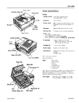
Mechanical
1 Interface Specifications 1
Dimensions and
weight:
Height:
8.3 inches (210 mm)
Width:
16.1 inches (410 mm)
excluding output and
input trays.
Depth:
15.4 inches (390 mm)
Weight:
Approx. 36 lb. (16 kg)
including paper cassette,
drum unit, and toner
cartridge.
Pin assignments for the parallel interface
The parallel interface connector pin assignments and a description
of the interface signals are shown in the table below.
Signal
Return
Pin
Pin
Signal
19
DATA
Signal to read data I”
20
DATA 1
DATA 2
DATA 3
DATA 4
DATA 5
DATA 6
DATA 7
DATA 6
These signals represent
information of me 1st to
8th bits of parallel data
respectively. Each signal
is at HIGH level when data
is logical 1 and LOW when
Recommended
duty cycle:
3,000 sheets per month
MPBF (Mean Prints
Between Failures):
30,000 sheets
MTBF (Mean Time
Between Failures):
Durability:
/
3,000 hours
10
21
22
23
24
25
26
27
I26
I
Direction Description
I
1 OUT
1 Acknowledge receiving data.
im
IN
Initial stage after data inside
buffer is printed.
FAULT
OUT
This signal becomes LOW
when the printer is:
lm
5 years or 300,000 sheets
(whichever comes first)
Electrical
Voltage:
120 VAC ± 10%, 60Hz ± 3Hz
Power consumption:
600W
I-
Controller hardware
RAM:
Total Memory:
2MB Memory
Board:
512K bytes
The optional 2MB memory board provides
enough memory for full-page (letter size),
300 dpi graphics plus additional
memory for downloading and other
purposes.
32
4MB Memory
Bard:
. off line
l in error state
l
malfunctioning.
Environment
Operation:
t
Temperature: 50 to 95°F (10 to 35°C)
Humidity:
Storage:
33
34
NC
35
36
NC
Not defined.
-
Not defined.
20 to 80% RH without
condensation
Temperature: 32 to 95°F (0 to 35°C)
Humidity:
l
20 to 80% RH without
condensation
l
WARNING: The life of consumables may be significantly
reduced if they are stored at temperatures outside the
range stated above.
.
Internal mode
HP LaserJet series II emulation
EPL-2
-
4MB increases capacity for downloading
of fonts, graphics, etc.
7/18/89
AU interface conditions are based on TTL. level. Both the rise
and fall of each signal must be less than 0.2 microseconds.
The column heading ‘Direction” refers to the direction of
signal flow as viewed from the printer.
“Return” denotes the twisted-pair return, to be connected at
signal ground level. For the interface wiring, be sure to use a
twisted-pair cable for each signal and to complete the
connection on the return side. These cables should be shielded
and connected to the chassis of the host computer and the
printer.
Laser Printers