1
User's Manual
CI - 4040
CI -4050
Acknowledgements
EPSON is a Trademark of Seiko Epson Corporation.
IBM is a Trademark of International Business Machines Corporation.
Proprinter is a Trademark of International Business Machines Corporation.
A Publication of
Output Solutions GmbH
Bavierstraße 1
D-40699 Erkrath
Federal Republic of Germany
January 2002
Great care has been taken to ensure that the information in this handbook is accurate and complete.
However, should any errors or omissions be discovered or should any user wish to make suggestions
for improving this handbook, please feel encouraged to send us the relevant details.
The contents of this manual are subject to change without notice.
Copyright © by Output Solutions GmbH.
All rights strictly reserved. Reproduction or issue to third parties in any form is not permitted without
written authorization from the publisher.
Safety Regulations
The printer PP 404 (CI - 4040) and PP 405 (CI - 4050) fulfils the safety
regulations according to UL 1950 and VDE (IEC 950) and CSA 22.2/No. 950 for
for computer systems.
The mains cable must be connected to a ground protected wall-socket. The
selected voltage of the printer needs to agree with the local voltage.
The power plug must be easily accessible at any time so that it can be
disconnected immediately in case of danger or for maintenance purposes..
Comme le câble de secteur sert de dipositif d'arrêt-urgence, sa connexion à
l'imprimante doit être tout le temps accessible.
Before installing the printer, check the surrounding conditions in which the
printer will be placed (see next page, Operating Environment and chapter 1).
During a thunderstorm you should never attempt to connect or disconnect any
data transfer cables.
The power supply should only be opened and checked by authorized personnel.
Repairs and maintenance beyond the descriptions of chapter 4 Maintenance
may only be attempted by authorized personnel as well. Repairs done
inappropriately may cause damage and severe danger for the user.
There are warning symbols to draw the user's attention to possible injuries:
This symbol is visible when the top cover has been
opened. It indicates that the print head is extremely
hot after long periods of printing.
Ce signal de danger se présente quand le cache
supérieur de l’imprimante soit retiré pour indiquer que
la tête d’impression peut être extrèmement chaude
après imprimer très longtemps.
I
Electromagnetic Compatibility
We certify that the equipment at issue,
Type: Printer PP 404 (CI - 4040) and PP 405 (CI - 4050)
corresponds to the law regulations ruling electromagnetic compatibility of
appliances (89/336/EWG) and, therefore, fulfils the requirements for conformity
marking with the CE-sign.
This equipment has been tested and found to comply with the limits for a
Class B digital device, pursuant to Part 15 of the FCC rules. These limits are
designed to provide reasonable protection against harmful interference in a
residential installation. This equipment generates, uses, and can radiate radio
frequency energy and, if not installed and used in accordance with the instruction manual, may cause interference to radio communications.
However, there is no guarantee that interference will not occur in a particular
installation. If this equipment does cause harmful interference to radio or
television reception, it can be determined by turning the equipment off and on.
The user is encouraged to try to correct the interference by one or more of the
following measures:
S
Reorient or relocate the receiving antenna.
S
Increase the separation between the equipment and receiver.
S
Connect the equipment to an outlet on a circuit different from the circuit
to which the receiver is connected.
S
Consult the dealer or an experienced radio/TV technician for help.
Shielded interface cables should be used with this unit to ensure compliance
with Class B limits.
Changes and modifications not explicitly allowed by the equipment's
manufacturer could void the user's authority to operate the equipment.
Changes et modifications pas expressément approuvés par le producteur
peuvent dévaluer l'autorité d'opérer l'équipement.
II
Operating Environment
Avoid installing the printer where it is exposed to moisture or heat (eg. direct sun
light).
S
S
S
Temperature:
+ 10EC to + 35EC (+50EF to +95EF)
Humidity:
20% to 80%
Humidity with Automatic (only printer CI - 4050)
Sheet Feeder (ASF):
30% to 70%
Slots and openings in the printer's housing are provided for ventilation. Always
ensure that these openings are not obstructed.
Also ensure that the cables at the rear of the printer do not interfere with the
output paper path.
When processing fanfold paper always place the printer with its front edge
slightly off the edge of the table.
III
Table of Contents
Preface . . . . . . . . . . . . . . . . . . . . . . . . . . . . . . . . . . . . . . . . . . . . . . . . . . . . . . . X
About this Manual . . . . . . . . . . . . . . . . . . . . . . . . . . . . . . . . . . . . . . . . . . . . . . . X
Conventions Used in this Guide . . . . . . . . . . . . . . . . . . . . . . . . . . . . . . . . . . . XIII
Abbreviations and Acronyms . . . . . . . . . . . . . . . . . . . . . . . . . . . . . . . . . . . . . XIII
1.Getting started . . . . . . . . . . . . . . . . . . . . . . . . . . . . . . . . . . . . . . . . . . . . . . 1-1
1.1
Unpacking the Printer CI - 4040 . . . . . . . . . . . . . . . . . . . . . . . . . . . . . 1-1
1.1.1 A First Look at the Printer CI - 4040 . . . . . . . . . . . . . . . . . . . . . . . . 1-2
1.2
Unpacking the Printer CI - 4050 . . . . . . . . . . . . . . . . . . . . . . . . . . . . . 1-3
1.2.1 A First Look at the Printer CI - 40540 . . . . . . . . . . . . . . . . . . . . . . . 1-4
1.3
Site Consierations . . . . . . . . . . . . . . . . . . . . . . . . . . . . . . . . . . . . . . . . 1-5
S Environment Conditions . . . . . . . . . . . . . . . . . . . . . . . . . . . . . . . . . . . 1-5
S Work Location . . . . . . . . . . . . . . . . . . . . . . . . . . . . . . . . . . . . . . . . . . . 1-5
S Power Requiremens . . . . . . . . . . . . . . . . . . . . . . . . . . . . . . . . . . . . . . 1-5
1.4
Transport Lock . . . . . . . . . . . . . . . . . . . . . . . . . . . . . . . . . . . . . . . . . . 1-6
S Re-packing information . . . . . . . . . . . . . . . . . . . . . . . . . . . . . . . . . . . 1-6
1.5
Installing the Personality Module (only Printer CI - 4050) . . . . . . . . . . 1-7
1.6
The Power Supply . . . . . . . . . . . . . . . . . . . . . . . . . . . . . . . . . . . . . . . . 1-8
S Main Input Voltage Selection . . . . . . . . . . . . . . . . . . . . . . . . . . . . . . . . 1-8
1.7
Power ON / OFF Switch . . . . . . . . . . . . . . . . . . . . . . . . . . . . . . . . . . . 1-9
1.8
Installing the Black Ribbon Cassette . . . . . . . . . . . . . . . . . . . . . . . . . 1-10
1.8.1 Replacing the Ribbon Cassette . . . . . . . . . . . . . . . . . . . . . . . . . . . 1-13
1.9
Tractor . . . . . . . . . . . . . . . . . . . . . . . . . . . . . . . . . . . . . . . . . . . . . . . . 1-14
S Inserting Fanfold Paper for the First Time . . . . . . . . . . . . . . . . . . . . . 1-14
1.10 Manual Sheet Insertion . . . . . . . . . . . . . . . . . . . . . . . . . . . . . . . . . . . 1-17
1.10.1 Printer CI - 4040 (Option) . . . . . . . . . . . . . . . . . . . . . . . . . . . . . . . 1-17
1.10.2 Printer CI - 4050 . . . . . . . . . . . . . . . . . . . . . . . . . . . . . . . . . . . . . . 1-18
1.11 Output Stacker (only Printer CI - 4050) . . . . . . . . . . . . . . . . . . . . . . . 1-19
1.12 Test Printouts . . . . . . . . . . . . . . . . . . . . . . . . . . . . . . . . . . . . . . . . . . 1-20
1.13 Connecting to a Computer . . . . . . . . . . . . . . . . . . . . . . . . . . . . . . . . 1-23
S Parallel/Serial Interface . . . . . . . . . . . . . . . . . . . . . . . . . . . . . . . . . . . 1-23
1.14 Emulation Selection . . . . . . . . . . . . . . . . . . . . . . . . . . . . . . . . . . . . . 1-24
IV
Table of Contents
2. Printer Operation . . . . . . . . . . . . . . . . . . . . . . . . . . . . . . . . . . . . . . . . . . 2-1
2.1
Control Panel . . . . . . . . . . . . . . . . . . . . . . . . . . . . . . . . . . . . . . . . . . . 2-1
2.2
Function Keys . . . . . . . . . . . . . . . . . . . . . . . . . . . . . . . . . . . . . . . . . . . 2-2
2.2.1 Short Description of Keys . . . . . . . . . . . . . . . . . . . . . . . . . . . . . . . . 2-2
S in the printer operation state READY or BUSY . . . . . . . . . . . . . . . . . 2-2
S in the printer operation state LOCAL . . . . . . . . . . . . . . . . . . . . . . . . . 2-2
2.2.2 Detail Description of Keys . . . . . . . . . . . . . . . . . . . . . . . . . . . . . . . 2-3
S in the printer operation state READY or BUSY . . . . . . . . . . . . . . . . . 2-3
S Quick Settings . . . . . . . . . . . . . . . . . . . . . . . . . . . . . . . . . . . . . . . . 2-3
S Top Row Keys . . . . . . . . . . . . . . . . . . . . . . . . . . . . . . . . . . . . . . . . . . 2-4
S Lower Row Keys . . . . . . . . . . . . . . . . . . . . . . . . . . . . . . . . . . . . . . . . . 2-4
S Vertical Position Adjustment . . . . . . . . . . . . . . . . . . . . . . . . . . . . . 2-4
S Fanfold Displacement . . . . . . . . . . . . . . . . . . . . . . . . . . . . . . . . . . 2-5
2.2.3 Meaning of the Keys in the LOCAL Mode . . . . . . . . . . . . . . . . . . . . 2-7
S Lower Row Keys . . . . . . . . . . . . . . . . . . . . . . . . . . . . . . . . . . . . . . . . . 2-7
2.3
Menu Mode . . . . . . . . . . . . . . . . . . . . . . . . . . . . . . . . . . . . . . . . . . . . . 2-8
2.3.1 To Activate the Menu . . . . . . . . . . . . . . . . . . . . . . . . . . . . . . . . . . . 2-9
2.3.2 To Confirm Selection . . . . . . . . . . . . . . . . . . . . . . . . . . . . . . . . . . 2-10
2.3.3 How to Save Settings . . . . . . . . . . . . . . . . . . . . . . . . . . . . . . . . . . 2-11
2.3.4 Quick Settings . . . . . . . . . . . . . . . . . . . . . . . . . . . . . . . . . . . . . . . . 2-12
3. Configuring the Printer . . . . . . . . . . . . . . . . . . . . . . . . . . . . . . . . . . . . .
3.1
What means Configuration . . . . . . . . . . . . . . . . . . . . . . . . . . . . . . . . .
3.2
Standard Configuration . . . . . . . . . . . . . . . . . . . . . . . . . . . . . . . . . . .
3.2.1 Standard Configuration for Printer CI - 4040 . . . . . . . . . . . . . . . . . .
3.2.2 Standard Configuration for Printer CI - 4050 . . . . . . . . . . . . . . . . . .
3.3
Explanation of the Printout . . . . . . . . . . . . . . . . . . . . . . . . . . . . . . . . .
3.4
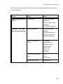
Explanation of Individual Menu Items . . . . . . . . . . . . . . . . . . . . . . . . .
Main Functions . . . . . . . . . . . . . . . . . . . . . . . . . . . . . . . . . . . . . . . . . . . . .
S MACRO SELECT . . . . . . . . . . . . . . . . . . . . . . . . . . . . . . . . . . . . . . . .
S CHANGE MACRO . . . . . . . . . . . . . . . . . . . . . . . . . . . . . . . . . . . . . . .
S INSTALLATION . . . . . . . . . . . . . . . . . . . . . . . . . . . . . . . . . . . . . . . . .
S SAVE . . . . . . . . . . . . . . . . . . . . . . . . . . . . . . . . . . . . . . . . . . . . . . . . .
S PRINT OUT . . . . . . . . . . . . . . . . . . . . . . . . . . . . . . . . . . . . . . . . . . . .
3-1
3-1
3-3
3-3
3-4
3-5
3-6
3-6
3-6
3-6
3-6
3-6
3-7
V
Table of contents
Main Function CHANGE MACRO . . . . . . . . . . . . . . . . . . . . . . . . . . . . . . . 3-7
S FONT . . . . . . . . . . . . . . . . . . . . . . . . . . . . . . . . . . . . . . . . . . . . . . . . . . 3-7
S PRINT QUALITY . . . . . . . . . . . . . . . . . . . . . . . . . . . . . . . . . . . . . . . . . 3-8
S FONT QUALITY . . . . . . . . . . . . . . . . . . . . . . . . . . . . . . . . . . . . . . . 3-8
S GRAPHICS QUALITY . . . . . . . . . . . . . . . . . . . . . . . . . . . . . . . . . . 3-8
S SUB/SUPER FONT . . . . . . . . . . . . . . . . . . . . . . . . . . . . . . . . . . . . . . . 3-8
S PITCH . . . . . . . . . . . . . . . . . . . . . . . . . . . . . . . . . . . . . . . . . . . . . . . . . 3-8
S LINE . . . . . . . . . . . . . . . . . . . . . . . . . . . . . . . . . . . . . . . . . . . . . . . . . . 3-8
S PAGE LENGTH . . . . . . . . . . . . . . . . . . . . . . . . . . . . . . . . . . . . . . . . . . 3-9
S VERT.POS.ADJ (Vertical Position Adjustment) . . . . . . . . . . . . . . . . 3-10
S LEFT MARGIN . . . . . . . . . . . . . . . . . . . . . . . . . . . . . . . . . . . . . . . . . 3-10
S RIGHT MARGIN . . . . . . . . . . . . . . . . . . . . . . . . . . . . . . . . . . . . . . . . 3-11
S TOP MARGIN . . . . . . . . . . . . . . . . . . . . . . . . . . . . . . . . . . . . . . . . . . 3-11
S BOTTOM MARGIN . . . . . . . . . . . . . . . . . . . . . . . . . . . . . . . . . . . . . . 3-12
S PERFORATION SKIP . . . . . . . . . . . . . . . . . . . . . . . . . . . . . . . . . . . . 3-12
S PAPER SOURCE . . . . . . . . . . . . . . . . . . . . . . . . . . . . . . . . . . . . . . . 3-12
S PAPER EXIT . . . . . . . . . . . . . . . . . . . . . . . . . . . . . . . . . . . . . . . . . . . 3-13
S EMULATION . . . . . . . . . . . . . . . . . . . . . . . . . . . . . . . . . . . . . . . . . . . 3-13
S CHARACTER SET . . . . . . . . . . . . . . . . . . . . . . . . . . . . . . . . . . . . . . 3-13
S LINE MODE . . . . . . . . . . . . . . . . . . . . . . . . . . . . . . . . . . . . . . . . . . . . 3-14
S $$-COMMANDS . . . . . . . . . . . . . . . . . . . . . . . . . . . . . . . . . . . . . . . . 3-14
S TEAR OFF MODE . . . . . . . . . . . . . . . . . . . . . . . . . . . . . . . . . . . . . . . 3-14
Main Function INSTALLATION . . . . . . . . . . . . . . . . . . . . . . . . . . . . . . . .
Sub-Function INTERFACE . . . . . . . . . . . . . . . . . . . . . . . . . . . . . . . . . . .
S BUFFER . . . . . . . . . . . . . . . . . . . . . . . . . . . . . . . . . . . . . . . . . . . . . .
S WORD LENGTH . . . . . . . . . . . . . . . . . . . . . . . . . . . . . . . . . . . . . . . .
S I/F Type . . . . . . . . . . . . . . . . . . . . . . . . . . . . . . . . . . . . . . . . . . . . . . .
S BAUD RATE . . . . . . . . . . . . . . . . . . . . . . . . . . . . . . . . . . . . . . . . . . .
S PARITY BIT . . . . . . . . . . . . . . . . . . . . . . . . . . . . . . . . . . . . . . . . . . . .
S PROTOCOL . . . . . . . . . . . . . . . . . . . . . . . . . . . . . . . . . . . . . . . . . . .
S CTS MODE . . . . . . . . . . . . . . . . . . . . . . . . . . . . . . . . . . . . . . . . . . . .
VI
3-15
3-15
3-15
3-15
3-15
3-15
3-15
3-15
3-15
Table of Contents
Sub-Function ADJUSTMENT . . . . . . . . . . . . . . . . . . . . . . . . . . . . . . . . .
S AGC POSITION . . . . . . . . . . . . . . . . . . . . . . . . . . . . . . . . . . . . . . . .
S PLATEN GAP . . . . . . . . . . . . . . . . . . . . . . . . . . . . . . . . . . . . . . . . . .
S AGC ADJUST . . . . . . . . . . . . . . . . . . . . . . . . . . . . . . . . . . . . . . . . . .
S PAPIER-IN ADJUST . . . . . . . . . . . . . . . . . . . . . . . . . . . . . . . . . . . . .
S CUT V-POS . . . . . . . . . . . . . . . . . . . . . . . . . . . . . . . . . . . . . . . . . . .
S UNI-DIRECT. CMD . . . . . . . . . . . . . . . . . . . . . . . . . . . . . . . . . . . . . .
S TRACT.FORM FEED MODE . . . . . . . . . . . . . . . . . . . . . . . . . . . . . .
3-16
3-16
3-17
3-17
3-17
3-18
3-18
3-19
Special Menu Items under INSTALLATION . . . . . . . . . . . . . . . . . . . . . .
S LANGUAGE . . . . . . . . . . . . . . . . . . . . . . . . . . . . . . . . . . . . . . . . . . .
S RESTORE SET UP . . . . . . . . . . . . . . . . . . . . . . . . . . . . . . . . . . . . .
S RECALL FACTORY . . . . . . . . . . . . . . . . . . . . . . . . . . . . . . . . . . . . .
S MENU ACCESS . . . . . . . . . . . . . . . . . . . . . . . . . . . . . . . . . . . . . . . .
S SELF TESTS . . . . . . . . . . . . . . . . . . . . . . . . . . . . . . . . . . . . . . . . . .
S HEX DUMP . . . . . . . . . . . . . . . . . . . . . . . . . . . . . . . . . . . . . . . . . . . .
3-19
3-19
3-19
3-19
3-20
3-21
3-21
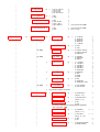
Menu Tree . . . . . . . . . . . . . . . . . . . . . . . . . . . . . . . . . . . . . . . . . . . . . Menu-1
4. Maintenance . . . . . . . . . . . . . . . . . . . . . . . . . . . . . . . . . . . . . . . . . . . . . .
S Preferred Materials . . . . . . . . . . . . . . . . . . . . . . . . . . . . . . . . . . . . . . .
4.1
Cleaning the Platen and Surrounding Areas . . . . . . . . . . . . . . . . . . .
S Print Test 3 . . . . . . . . . . . . . . . . . . . . . . . . . . . . . . . . . . . . . . . . . . . . .
4.2
Cleaning Procedure . . . . . . . . . . . . . . . . . . . . . . . . . . . . . . . . . . . . . .
4.3
User Replaceable Parts . . . . . . . . . . . . . . . . . . . . . . . . . . . . . . . . . . .
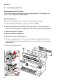
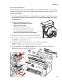
S Replacement of the Print Head . . . . . . . . . . . . . . . . . . . . . . . . . . . . .
S Print Head Removal . . . . . . . . . . . . . . . . . . . . . . . . . . . . . . . . . . .
S Print Head Installation . . . . . . . . . . . . . . . . . . . . . . . . . . . . . . . . . .
S Replacement of the Platen . . . . . . . . . . . . . . . . . . . . . . . . . . . . . . . . .
S To Remove the Platen . . . . . . . . . . . . . . . . . . . . . . . . . . . . . . . . .
S To Install the Platen . . . . . . . . . . . . . . . . . . . . . . . . . . . . . . . . . . .
4-1
4-1
4-1
4-2
4-3
4-4
4-4
4-4
4-5
4-6
4-6
4-7
VII
Table of contents
5. Trouble Shooting and Diagnostics . . . . . . . . . . . . . . . . . . . . . . . . . . . . 5-1
S How to Use this section . . . . . . . . . . . . . . . . . . . . . . . . . . . . . . . . . . . . 5-1
5.1
Power-related Problems . . . . . . . . . . . . . . . . . . . . . . . . . . . . . . . . . . . 5-2
5.2
Error Messages . . . . . . . . . . . . . . . . . . . . . . . . . . . . . . . . . . . . . . . . . . 5-2
5.3
No Printout . . . . . . . . . . . . . . . . . . . . . . . . . . . . . . . . . . . . . . . . . . . . . 5-8
5.4
Operation-related Problems . . . . . . . . . . . . . . . . . . . . . . . . . . . . . . . . 5-9
5.5
Print-related Problems . . . . . . . . . . . . . . . . . . . . . . . . . . . . . . . . . . . . 5-10
5.6
Ribbon or Carriage-related Problems . . . . . . . . . . . . . . . . . . . . . . . . 5-12
5.7
Print Tests . . . . . . . . . . . . . . . . . . . . . . . . . . . . . . . . . . . . . . . . . . . . . 5-12
6. Colour Option (only Printer CI - 4050) . . . . . . . . . . . . . . . . . . . . . . . . . . . 6-1
6.1
Installing the Colour Option . . . . . . . . . . . . . . . . . . . . . . . . . . . . . . . . . 6-1
6.2
Installing the 4-Colour Ribbon . . . . . . . . . . . . . . . . . . . . . . . . . . . . . . . 6-4
7. Automatic Sheet Feeder Cassette (ASF) (only Printer CI - 4050) . . . . .
7.1
Checking the Delivery Consignment . . . . . . . . . . . . . . . . . . . . . . . . . .
7.1.1 Prepare the ASF Cassettes . . . . . . . . . . . . . . . . . . . . . . . . . . . . . .
7.1.2 Installing the ASF Cassettes . . . . . . . . . . . . . . . . . . . . . . . . . . . . .
7.1.3 Removing theASF Cassette . . . . . . . . . . . . . . . . . . . . . . . . . . . . .
7.1.4 Inserting Paper . . . . . . . . . . . . . . . . . . . . . . . . . . . . . . . . . . . . . . .
7.2
Replacing of the ASF Pick-up Rollers . . . . . . . . . . . . . . . . . . . . . . . . .
7.2.1 To Remove the ASF Pick-up Rollers . . . . . . . . . . . . . . . . . . . . . . .
7.2.2 To Install the Pick-up Rollers . . . . . . . . . . . . . . . . . . . . . . . . . . . . .
7-1
7-1
7-2
7-3
7-5
7-6
7-8
7-8
7-9
8. Technical Data . . . . . . . . . . . . . . . . . . . . . . . . . . . . . . . . . . . . . . . . . . . . . 8-1
VIII
Table of Contents
Appendices
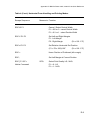
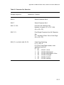
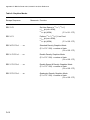
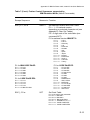
System Interface Descriptions . . . . . . . . . . . . . . . . . . . . . . . . . . A-1
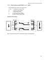
Serial Interface RS 232 C / RS 422 . . . . . . . . . . . . . . . . . . . . . . . . . . A-2
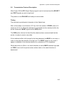
Transmission Protocols . . . . . . . . . . . . . . . . . . . . . . . . . . . . . . . . . . . A-3
Parallel Centronics® Interface . . . . . . . . . . . . . . . . . . . . . . . . . . . . . . . A-9
Shared Operation . . . . . . . . . . . . . . . . . . . . . . . . . . . . . . . . . . . . . . . A-12
Appendix A
1
2
3
4
Appendix B
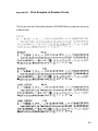
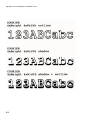
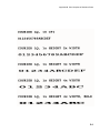
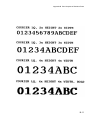
Print Samples of Resident Fonts . . . . . . . . . . . . . . . . . . . . . . . . B-1
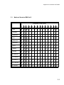
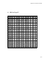
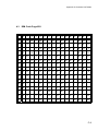
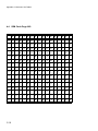
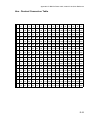
Appendix C
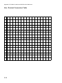
Character Set Tables . . . . . . . . . . . . . . . . . . . . . . . . . . . . . . . . . C-1
Appendix D
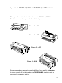
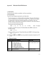
IBM ProPrinter Quick Reference . . . . . . . . . . . . . . . . . . . . . . . . D-1
Appendix E
EPSON LQ Quick Reference . . . . . . . . . . . . . . . . . . . . . . . . . . . E-1
Appendix F
Barcode Quick Reference . . . . . . . . . . . . . . . . . . . . . . . . . . . . . . F-1
Appendix G
- Information for the System Manager . . . . . . . . . . . . . . . . . . . . . G-1
IX
Preface
About this Manual
This manual covers the printer in combination with fanfold and manual paper
source and with an interface module (Personality Module).
The Personality Module (PM) is an integral part of the printer, and the type of PM
used determines the functionality of the printer especially regarding the user and
system interface.
The structure of this manual is such that the operator is led step-by-step through
the various procedures. It starts with the unpacking and setting-up, moves on to
detailed instructions for operating the printer and ends with the mounting of
options.
The manual is divided into the following chapters:
1. Getting Started
This chapter covers the unpacking and setting-up of the printer and the
installation of the ribbon cassette. By the end of this chapter the printer
should be fully functional and tested in its primary form. It is not yet
connected to the host computer system and no options are mounted.
2. Operating the Printer
This chapter discusses in great detail the operation of the operator panel,
menu functions, and the general operation of the menu.
3. Configuring the Printer
This chapter explains how to configure the printer so that it can communicate
with the corresponding system environment. Then this chapter thoroughly
describes the printer's operating controls. In the last part you will find
explanations of individual menu items. At The end of this chapter you will find
the Menu tree.
X
Preface
4. Maintenance
shows how to clean the printer and how to replace the platen and the print
head.
5. Trouble Shooting and Diagnostics
suggests how to identify and correct simple problems.
6. Colour Option (only for Printer CI - 4050)
This is a brief description of the colour option. Supplements enclosed in the
packaging of options may be inserted here.
7. Automatic Sheet Feeder Cassettes (ASF) (only for Printer CI - 4050)
This chapter shows how to handle the ASF Cassettes.
8. Technical Data
All technical details or data about the printer can be found here.
Appendix
A. Interface Description
This chapter gives hints about possibilities to connect the printer to the
various computer systems and explains particularities depending on the
version of the operating system. Additionally, cable connection is illustrated.
B. Print Samples of Resident Fonts
C. Character Set Table
All printer supported character sets are listed in this chapter.
XI
Preface
D. Control Codes
Quick reference for IBM Proprinter and IBM Proprinter AGM (4207, 4208
XL 24) Emulation.
E. Control Codes
Quick reference for EPSON LQ 2550 / 1060 /ESC/P2 Emulation.
F. Control Codes
Quick reference for Barcode programming.
G. Miscellaneous
System Manager Information
XII
Preface
Conventions Used in this Guide
The following conventions are used:
Bold
Headlines and important information.
Note:
Contains special advice to facilitate handling.
Caution:
Contains important information to prevent damage
of the equipment.
[ENTER]
Key functions are always depicted in brackets or
you will find the symbol of the key e.g
.
Abbreviations and Acronyms
ASF
Automatic Sheet Feeder Cassette for cut sheets and form sets
DRAFT
Draft Quality
EE
Eastern European
LCD
Liquid Crystal Display
LED
Light Emitting Diode
LQ
Letter Quality
MACRO
User defined group (1 bis 4) of stored parameter
NLQ
Near Letter Quality
PH
Print Head
PM
Interface (Personality Module)
Note!
The following chapters describe the two printers:
S CI - 4040
Fanfold printer
S CI - 4050
Multi purpose printer
The operation of both printers is mostly alike. In most illustrations, the printer
CI - 4050 is used. In case there are differences in the handling you will find the
note CI - 4040 or CI - 4050.
XIII
1. Getting Started
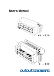
1.1 Unpacking the Printer CI - 4040
Check each item against the check list detailed below. Contact your delivery
agent immediately if any item is missing or damaged.
The printer package should contain the following:
Printer (1)
- Ribbon cassette (2)
- Power cord (3)
- Quick Reference Guide (4)
- CD-ROM (5)
Caution:
Do not connect to the mains until the mains voltage selection has
been checked.
1-1
Getting Started
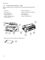
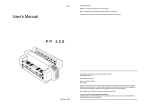
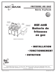
1.1.1 A First Look at the Printer CI - 4040
Before installing the printer, spend some time familiarizing yourself with the
printer.
-
Printer (1)
Top Cover (3)
Paper Supports (5)
Control Panel (7)
Serial / Parallel Input (9)
Power Switch (11)
-
Ribbon Cassette (2)
Tractor for Continuous Paper (4)
Front Cover (6)
Tear Off Edge (8)
Power Cord Socket (10)
11
2
7
3
4
5
10
1
6
9
8
- Manual Front Insertion Guide (12) (Option only)
12
1-2
Getting Started
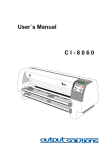
1.2 Unpacking the Printer CI - 4050
Check each item against the check list detailed below. Contact your delivery
agent immediately if any item is missing or damaged.
The printer package should contain the following:
- Output Stacker (1)
- Ribbon cassette (2)
- Printer (3)
- Quick Reference Guide (4)
- Personality Module (PM) (5) - Power Cord (6)
- CD-ROM (7)
5
1
2
3
6
7
4
A separate box contains the Personality Module (5)
Caution:
Do not connect to the mains until the mains voltage selection has
been checked and the PM is installed.
Note:
Save all packing material and boxes for future transportation of the
printer.
The User´s Manual and the printer drivers for Windows ® are
available on the enclosed CD-ROM
1-3
Getting Started
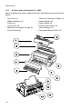
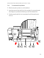
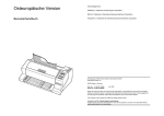
1.2.1 A First Look at the Printer CI - 4050
Before installing the printer, spend some time familiarizing yourself with the
printer.
-
Top Cover (1)
Ribbon Cassette (2)
Printer (3)
Front Cover (4)
Manual Front Insertion Guide (5)
Control Panel (6)
1-4
-
Tractor for Continuous Paper (7)
Output Stacker (8)
Power Switch (9)
Power Cord Socket (10)
Tear Off Edge (11)
Personality Module (PM) (12)
Getting Started
1.3
Site Considerations
Environment Conditions
- Install the printer in an area away from any heat source, air conditioner or
strong drafts.
-
Avoid installing the printer in a dusty or humid environment.
Work Location
- Place the printer on the stand or a flat, solid level area such as a desk.
-
Slots and openings in the printer's housing are provided for ventilation;
always ensure that these openings are not obstructed.
-
When processing fanfold paper always place the printer with its front edge
slightly off the edge of the table.
-
Also ensure that the cables at the rear of the printer do not interfere with the
output paper path.
Power Requirements
- No special wiring is required. A typical office wall outlet is sufficient.
-
Do not plug into the same wall outlet other equipment besides the printer
such as coffee machines, copy machines or air conditioners.
1-5
Getting Started
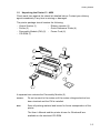
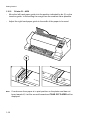
1.4
Transport Lock
You will find a red shipping tab under the top cover (1).
Grasp the top cover (1) on the left and right, lift it and remove the transport
locking clip (2) from the print head drive belt.
Re-packing Information
Note:
Save all packing material and boxes for future transportation of the
printer.
To ensure maximum protection when transporting the printer, always
-
1-6
Remove any installed paper handling option.
Remove the output stacker and the mains cable.
Remove the ribbon cassette.
Reposition the transport locking clip.
Pack the printer in its original packing material and ship in its original box.
Getting Started
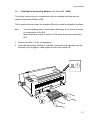
1.5
Installing the Personality Module (only Printer CI - 4050)
The printer functions only in combination with an installed interface module,
called a Personality Module (PM).
The illustration below shows the standard PM with a serial and parallel interface.
Note
-
To avoid damage due to electrostatic discharge, do not touch the pins
or components of the PM.
Never attempt to install or remove a PM while the printer is switched
ON.
1. Remove the PM (1) from its packaging.
2. Insert the Personality Module (1) with the component side upwards until the
connector fully engages. Hand tighten the two lock screws (2).
1-7
Getting Started
1.6
The Power Supply
Mains Voltage Selection
In general, the mains voltage selection is determined at factory site.
Since an incorrect voltage selection can seriously damage the printer, please
pay special attention to the following:
Make sure that the specified voltage on the voltage selector (1) corresponds to
your mains voltage:
-
either 230 V for 180 to 264 V alternating current
or 115 V for 90 to 140 V alternating current.
If it is necessary to change the voltage, slide the selector button to the required
voltage selection.
Connect the printer to the mains using the power cord (2). First connect the
cable to the power cord socket and then to the mains.
Note:
1-8
As the power cord serves as a safety cut-off, its connection to the printer
must be accessible any time.
Getting Started
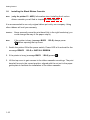
1.7
Power ON/OFF Switch
The power ON/OFF switch (1) turns the printer's power supply ON or OFF.
When switched ON the printer performs an internal self-test which checks the
electronics, the print head carriage movement and the interface. Power ON is
indicated by a green LED on the operator panel and shows TEST.... .
If the message INSTALL RIBBON is shown, follow the steps in paragraph 1.8
Installing the Ribbon Cassette.
After inserting the ribbon press
to continue. When the internal test has been
completed successfully the display shows READY 1 ELQ or BUSY 1 ELQ in
case data has already been transmitted.
Note:
If the display shows anything different please refer to chapter 5
Troubleshooting and Diagnostics.
1-9
Getting Started
1.8
Installing the Black Ribbon Cassette
Note:
(only for printer CI - 4050) Information about installing the 4-colourribbon cassette you will find in chapter 6 Colour option.
It is recommended to use only original ribbon put out by our company. Using
other ribbons will void your warranty.
Caution:
Never manually move the print head fully to the right hand stop (you
could change the way of the paper output).
Note:
If the printer is busy (message BUSY 1 ELQ) always press
before opening the top cover.
1. Switch the printer ON at the power switch; Power LED is lit and wait for the
message READY 1 ELQ or INSTALL RIBBON.
2. If the printer is busy (message BUSY 1 ELQ) press
.
3. Lift the top cover to gain access to the ribbon cassette mountings. The print
head will move to the correct position, aligned with the cut-out in the paper
guide plate to facilitate the installation of the ribbon cassette.
1-10
Getting Started
4. Remove any excess slack by turning the green knob on the ribbon cassette
clockwise. Move the ribbon feed guide to the position indicated on the plastic
cover of the cassette.
5. Position the lower mounting pin (a) on the guide to the right. Slide the
cassette downward. In this position, the green ribbon feed guide touches the
green plastic clip.
1-11
Getting Started
6. Move the cassette toward you until you hear a click on both sides. Swing the
ribbon underneath the print head for the final click. The audible clicks
indicate that the mounting pins have engaged properly.
click !
Note
click !
When installed correctly the ribbon cassette has a sloping position.
7. Move the print head back and forth to settle the ribbon in the correct position.
8. If necessary remove excess ribbon slack by turning the green knob
clockwise.
9. Close the top cover and press [START/STOP]
1-12
.
Getting Started
1.8.1
Replacing the Ribbon Cassette
Caution:
The print head may be very hot immediately after printing!
-
Close the top cover and switch the printer ON. Lift the top cover after the
display shows the message READY 1 ELQ to gain access to the ribbon
cassette mountings. The print head will move to the correct position, aligned
with the cut-out in the paper guide plate to facilitate the installation of the
ribbon cassette.
-
Now swing the lower part of the ribbon to the back.
In this way the mounting pins loosen from the lower position.
-
Then press the upper part of the ribbon to the back. The upper mounting
pins get free and the ribbon can be taken out.
1.
2.
Note:
To install a new ribbon cassette please see 1.8 Installing the Ribbon
Cassette (see pages before).
1-13
Getting Started
1.9
Tractor
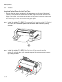
Inserting Fanfold Paper for the First Time
- Ensure that the printer is placed in the depression on the top of the stand
(option). If the printer is used without a stand, align the printer with the front
edge of the table. The cables at the back of the printer should be tucked into
the cable clips in order not to block the paper path.
Note:
(only for printer CI - 4040) If the manual front insertion guide (1) (Option)
is in use, pull it upwards against the resistance and remove by pulling
forward.
Note:
(only for printer CI - 4050) Hold the front of the manual insertion
guide (4) on both sides, pull upwards against the resistance and remove
by pulling forward.
1-14
Getting Started
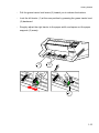
-
Pull the green tractor lock levers (2) toward you to release the tractors.
-
Lock the left tractor (1) at the new position by pressing the green tractor level
(2) backward.
-
Roughly adjust the right tractor to the paper width, and space out the paper
supports (3) evenly.
1
3
2
1-15
Getting Started
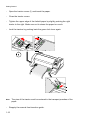
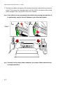
-
Open the tractor covers (1) and insert the paper.
-
Close the tractor covers.
-
Tighten the upper edge of the fanfold paper by slightly pushing the right
tractor to the right. Make sure not to stress the paper too much.
-
Lock the tractors by pushing back the green lock lever again.
Note:
-
The pins of the tractor must be centered in the transport punches of the
paper
Reapply the manual front insertion guide.
1-16
Getting Started
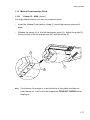
1.10 Manual Front Insertion Guide
1.10.1
Printer CI - 4040 (Option)
For single sheet insertion you can use a special option.
-
Insert the Manual Front Isertion Guide (1) above the tractors and push it
down.
-
Release the screw (2) of the left hand paper guide (3). Adjust the guide (3)
to the position of the left margen and fix it with the screw (2).
3
1
2
Note:
If continuous form paper is in print position on the platen and has not
been teared off, it will be moved forward and TEAR OFF PAPER will be
displayed.
1-17
Getting Started
1.10.2
Printer CI - 4050
- Move the left hand paper guide into the position indicated by ±
• (2) on the
insertion guide. In this setting the margin has the smallest value possible.
-
Adjust the right hand paper guide to the width of the paper to be used.
Note:
1-18
If continuous form paper is in print position on the platen and has not
been teared off, it will be moved forward and TEAR OFF PAPER will be
displayed.
Getting Started
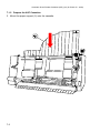
1.11 Output Stacker (only printer CI - 4050)
Install the output stacker (5) into one of the two rails in the top cover (2).
The meaning of the two Positions:
-
for paper with 80 g/m² or thicker use the steeper position (left picture);
-
for thinner paper use the less inclined position (right picture).
-
Check, if the manual sheet insertion is installed.
1-19
Getting Started
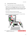
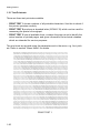
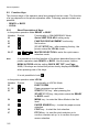
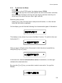
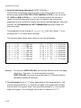
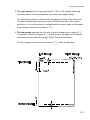
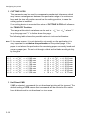
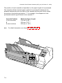
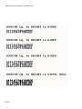
1.12 Test Printouts
There are three test printouts available.
- PRINT TEST 1 shows a pattern of all printable characters. Use this to check if
the printer operates correctly.
- PRINT TEST 2 produces a standard letter (ECMA-132) which can be used for
measuring the printer's throughput.
- PRINT TEST 3 lists all available fonts, contains the page count to identify the
actual number of printed pages, and gives information on technical releases
which are intended for service purposes.
The print tests are printed using the parameters set in the menu, e.g. font, pitch
etc. Refer to section "Menu Mode" for details.
ABCDEFGHIJKLMNOPQRSTUVWXYZabcdefghijklmnopqrstuvwxyz0123456789!§
§ABCDEFGHIJKLMNOPQRSTUVWXYZabcdefghijklmnopqrstuvwxyz0123456789!
!§ABCDEFGHIJKLMNOPQRSTUVWXYZabcdefghijklmnopqrstuvwxyz0123456789
9!§ABCDEFGHIJKLMNOPQRSTUVWXYZabcdefghijklmnopqrstuvwxyz012345678
89!§ABCDEFGHIJKLMNOPQRSTUVWXYZabcdefghijklmnopqrstuvwxyz01234567
789!§ABCDEFGHIJKLMNOPQRSTUVWXYZabcdefghijklmnopqrstuvwxyz0123456
6789!§ABCDEFGHIJKLMNOPQRSTUVWXYZabcdefghijklmnopqrstuvwxyz012345
56789!§ABCDEFGHIJKLMNOPQRSTUVWXYZabcdefghijklmnopqrstuvwxyz01234
456789!§ABCDEFGHIJKLMNOPQRSTUVWXYZabcdefghijklmnopqrstuvwxyz0123
3456789!§ABCDEFGHIJKLMNOPQRSTUVWXYZabcdefghijklmnopqrstuvwxyz012
23456789!§ABCDEFGHIJKLMNOPQRSTUVWXYZabcdefghijklmnopqrstuvwxyz01
123456789!§ABCDEFGHIJKLMNOPQRSTUVWXYZabcdefghijklmnopqrstuvwxyz0
0123456789!§ABCDEFGHIJKLMNOPQRSTUVWXYZabcdefghijklmnopqrstuvwxyz
z0123456789!§ABCDEFGHIJKLMNOPQRSTUVWXYZabcdefghijklmnopqrstuvwxy
yz0123456789!§ABCDEFGHIJKLMNOPQRSTUVWXYZabcdefghijklmnopqrstuvwx
xyz0123456789!§ABCDEFGHIJKLMNOPQRSTUVWXYZabcdefghijklmnopqrstuvw
wxyz0123456789!§ABCDEFGHIJKLMNOPQRSTUVWXYZabcdefghijklmnopqrstuv
vwxyz0123456789!§ABCDEFGHIJKLMNOPQRSTUVWXYZabcdefghijklmnopqrstu
uvwxyz0123456789!§ABCDEFGHIJKLMNOPQRSTUVWXYZabcdefghijklmnopqrst
tuvwxyz0123456789!§ABCDEFGHIJKLMNOPQRSTUVWXYZabcdefghijklmnopqrs
stuvwxyz0123456789!§ABCDEFGHIJKLMNOPQRSTUVWXYZabcdefghijklmnopqr
rstuvwxyz0123456789!§ABCDEFGHIJKLMNOPQRSTUVWXYZabcdefghijklmnopq
qrstuvwxyz0123456789!§ABCDEFGHIJKLMNOPQRSTUVWXYZabcdefghijklmnop
pqrstuvwxyz0123456789!§ABCDEFGHIJKLMNOPQRSTUVWXYZabcdefghijklmno
opqrstuvwxyz0123456789!§ABCDEFGHIJKLMNOPQRSTUVWXYZabcdefghijklmn
nopqrstuvwxyz0123456789!§ABCDEFGHIJKLMNOPQRSTUVWXYZabcdefghijklm
mnopqrstuvwxyz0123456789!§ABCDEFGHIJKLMNOPQRSTUVWXYZabcdefghijkl
lmnopqrstuvwxyz0123456789!§ABCDEFGHIJKLMNOPQRSTUVWXYZabcdefghijk
klmnopqrstuvwxyz0123456789!§ABCDEFGHIJKLMNOPQRSTUVWXYZabcdefghij
jklmnopqrstuvwxyz0123456789!§ABCDEFGHIJKLMNOPQRSTUVWXYZabcdefghi
ijklmnopqrstuvwxyz0123456789!§ABCDEFGHIJKLMNOPQRSTUVWXYZabcdefgh
hijklmnopqrstuvwxyz0123456789!§ABCDEFGHIJKLMNOPQRSTUVWXYZabcdefg
ghijklmnopqrstuvwxyz0123456789!§ABCDEFGHIJKLMNOPQRSTUVWXYZabcdef
fghijklmnopqrstuvwxyz0123456789!§ABCDEFGHIJKLMNOPQRSTUVWXYZabcde
efghijklmnopqrstuvwxyz0123456789!§ABCDEFGHIJKLMNOPQRSTUVWXYZabcd
defghijklmnopqrstuvwxyz0123456789!§ABCDEFGHIJKLMNOPQRSTUVWXYZabc
cdefghijklmnopqrstuvwxyz0123456789!§ABCDEFGHIJKLMNOPQRSTUVWXYZab
bcdefghijklmnopqrstuvwxyz0123456789!§ABCDEFGHIJKLMNOPQRSTUVWXYZa
abcdefghijklmnopqrstuvwxyz0123456789!§ABCDEFGHIJKLMNOPQRSTUVWXYZ
Zabcdefghijklmnopqrstuvwxyz0123456789!§ABCDEFGHIJKLMNOPQRSTUVWXY
PRINT TEST 1
1-20
Getting Started
Eilzustellung
Norddeutsche Farbwerke KG
Herrn Dr. Grauert
Große Elbstraße 64
2000 Hamburg 4
Org. III 5/37
17.04.75
H-A
Volkmann
4 34
Vordruckgestaltung für den allgemeinen Schriftverkehr, für das Bestell- und Rechnungswesen
22.04.75
E i l t
Sehr geehrter Herr Dr. Grauert,
Sie können das Schreiben der Briefe, Bestellungen, Rechnungen usw.
sowie das Bearbeiten des Schriftguts rationalisieren, wenn die
Vordrucke Ihres Unternehmens den folgenden Normen entsprechen:
DIN 676 Geschäftsbrief; Vordrucke A4
DIN 677 -; Vordruck A5
DIN 679 Geschäftspostkarte; Vordrucke A6
DIN
DIN
DIN
DIN
DIN
4991
4992
4993
4994
4998
Vordrucke im Lieferantenverkehr; Rechnung
-; Bestellung (Auftrag)
-; Bestellungsannahme (Auftragsbestätigung)
-; Lieferschein/Lieferanzeige
Entwurfsblätter für Vordrucke
Diese Normen enthalten alle Einzelheiten für den sinnvollen und
zweckmäßigen Aufdruck. Wenn dazu bei der Beschriftung genormter
Vordrucke DIN 5008 'Regel für Maschinenschreiben' beachtet wird,
entstehen übersichtliche und werbewirksame Schriftstücke.
Die beifgefügten 6 Mustervordrucke zeigen, daß das Beachten der
Normen die künstlerische und werbewirksame Gestaltung der Vordrucke nicht ausschließt.
Da wir uns auf die Herstellung genormter Vordrucke spezialisiert
haben, können wir besonders billig liefern. Eine Probestellung
wird Sie und Ihre Geschäftsfreunde von den Vorteilen überzeugen.
Mit bester Empfehlung
NORAG
Druckerei und Verlagshaus KG
Herrmann
Anlagen
6 Mustervordrucke
PRINT TEST 2
1-21
Getting Started
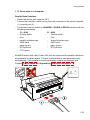
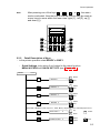
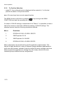
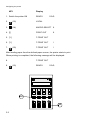
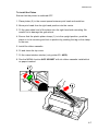
To start a print test:
1. Switch the printer ON (display shows READY 1 ELQ).
The following identifies the keys to press
and the corresponding operator panel
displays.
KEY
Display
2.
(93)
LOCAL
3.
(94)
MACRO SELECT
6
4. [\] -- [\]
INSTALLATION
6
5. [Y]
7 INTERFACE
6
6. [[] -- [[]
7 SELF TEST
6
7. [Y]
7 PRINT TEST 1
Use [\] to select PRINT TEST 2 or 3.
8. [Y]
9.
(93)
7 PRINT TEST 1
*
PRINT TEST 1
*
The printer starts to print using paper from the defined paper source.
To stop the print test:
1.
(93)
2. [Z]
3.
1-22
(93)
7 PRINT TEST 1
*
7 SELF TEST
6
READY
1 ELQ
Getting Started
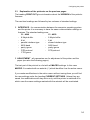
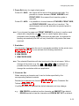
1.13 Connection to a Computer
Parallel/Serial Interface
- Switch the printer and computer OFF.
- Connect the interface cable coming from the computer to the printer's parallel
(1) or serial port (2).
- The printer is set by default to SHARED or PARALL./RS232 interface with the
following parameters:
CI - 4040
CI - 4050
- 8 Kbyte buffer
8 Kbyte buffer
- 8 bit
8 bit
- parallel interface type
shared interface type
- 9600 baud
9600 baud
- parity ignore
parity ignore
- DTR protocol
DTR protocol
- CTS ignore.
SHARED means that, after Power-ON, both the serial and the parallel interfaces
are available for data transfer. The port to which data is sent becomes active
automatically. If the parallel or serial parameters need to be changed, see
Chapter 2, Menu Mode, and Appendix A, Interface Description.
1-23
Getting Started
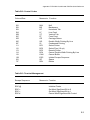
1.14 Emulation Selection
The following emulations are included in the printer:
- EPSON LQ (Default)
in Macro 1
- IBM ProPrinter
in Macro 2
- IBM ProPrinter AGM
in Macro 3
- EPSON LQ
in Macro 4
To change from one emulation to another, follow the procedure below. The
example shows the keys to press along with the display information for a change
from EPSON LQ in macro 1 to IBM ProPrinter in macro 2.
1.
Switch the printer ON. The display shows READY 1 ELQ.
2.
MACRO 2
3.
[Y]
READY
2 IPP
The information READY 2 IPP indicates the selected macro and the
emulation of this macro, for example:
1
2
3
4
Note:
1-24
ELQ
IPP
AGM
ELQ
Macro 1 with Epson Emulation
Macro 2 with IBM Proprinter Emulation
Macro 3 with IBM Proprinter AGM Emulation
Macro 4 with Epson Emulation.
A number of VALUE settings (Print Quality, Page Length, Margin, or
Paper Source) is summarized in a "Macro". It is possible to have a
total of four macros, each with a different summary of VALUE
settings.
2.
2.1
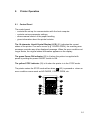
Printer Operation
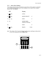
Control Panel
The control panel
- controls the set-up for communication with the host computer
- controls various parameter settings
- allows manual control of the paper handling
- gives information about the printer's status.
The 16-character Liquid Crystal Display (LCD) (51) indicates the current
status of the printer. If an error occurs (e.g. COVER OPEN), the resulting error
message overrides any other displayed message. When the error condition not
longer exists, the original status information appears on the display.
The green Power ON indicator (53) is lit when the printer is supplied with
power by setting the power ON/OFF switch to ON.
The yellow STOP indicator (52) is lit when the printer is in the STOP mode.
The printer enters the STOP mode either when
(93) is pressed or when an
error condition occurs such as NO PAPER, COVER OPEN, etc.
2-1
Printer Operation
2.2 Function Keys
The function keys of the operator panel are grouped into two rows. The function
of a key depends on the printer operation state. Following operation states are
possible:
- READY or BUSY
- LOCAL
2.2.1
Short Description of Keys
- in the printer operation state READY or BUSY
Number Symbol
Functionality in ONLINE/READY Mode
90
Quick VERT.POS.ADJ. setting entry
91
FANFOLD DISPLACEMENT mode entry
92
No function
93
[START/STOP] key - after pressing the key, the
printer enters the LOCAL mode.
94-97
MACRO SELECTION to enter the quick macro
selection mode.
Note:
It is possible to lock the function of the above described keys in the
printer operation state READY or BUSY. Use the menu function
MENU ACCESS with the setting QUICK SET OFF (see Page
3-20). If the keys are locked the printer shortly displays LOCKED
when pressing one of the keys.
It is not possible to lock
.
- in the printer operation state LOCAL
Number Symbol
Functionality in LOCAL Mode
90
EJECT FORM
91, 92
Paper movement up and down
93
START/STOP key - after pressing the
[START/STOP] key, the printer enters the READY
or BUSY mode.
94
MENU key - to enter the Menu Mode in the first
level.
95
PAPER SOURCE key - to start the paper source
selection.
96
FONT key - to start the font selection.
97
PITCH key - to start the pitch selection or to
confirm a certain set up, or to confirm the quick
macro selection.
2-2
Printer Operation
Note:
After pressing one of the keys
,
.
, or
the menu
mode is activated. Now the keys of the top row can only be used as
cursor keys to move within the menu tree (right [Y], left [Z], up [[]
and down [\]).
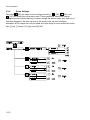
2.2.2 Detail Description of Keys
- in the printer operation state READY or BUSY
- Quick Settings (only active if not locked in the menu function
MENU ACCESS with QUICK SET OFF (see Chapter 3)).
READY
1 ELQ
Y
MENU
MACRO 1
*
Select
Exit
Y
MACRO 2
Select
Exit
aa
aa
MACRO 3
abc
abc
MACRO 4
Y
Select
Exit
Y
Select
Exit
TRACTOR or MANUAL (and only for CI - 4050: BIN x): depending on the selected paper source
TRACTOR V
0
*
[
Up
Down
FANFOLD DIS. 0
Y
Select
Offset
Exit
Offset
2-3
Printer Operation
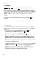
- Top Row Keys
The Quick Macro Selection mode is entered when one of the top row keys
,
,
or
is pressed. From the left to the right macro 1 to macro
4 will be selected. Pressing of key
causes the printer to change in the
STOP-mode and in the display appears the message MACRO 2. Pressing
key [Y] confirms the macro selection and changes the printer into the READY
or BUSY mode. After this sample the printer the message on the display is
READY 2 IPP. That means macro 2 with IBM ProPrinter emulation is
selected.
If you press one of the above described key erroneously, press
correction.
Note:
for
Macro selection means a change of all configuration parameters of the
macro concerned.
- Lower Row Keys
In case a certain application requires a specific vertical positioning of the
printout on a continuous form, two possibilities are provided for the READY or
BUSY mode:
- vertical position adjustment VERT.POS.ADJ. with key
(90)
- fanfold displacement FANFOLD DIS with key
(91).
- Vertical Position Adjustment (VERT.POS.ADJ.)
(90)
This can be set differently for each macro to exactly position the printout in
relation to the top edge of the form in use. Using this function, the TOP
MARGIN and BOTTOM MARGIN settings are taken into account as well.
The parameter is part of the printer´s configuration set up memory and can
be stored with the SAVE function.
The VERT. POS.ADJ. mode can directly be called up in the status READY
or BUSY by pressing key
. In this case a set up is possible for the
actually paper source of the selected macro. With TRACTOR V, or
MANUAL V (and only for printer CI - 4050 also BIN x V (x = 1-3)) the
printer asks for the value of the actually paper source.
2-4
Printer Operation
This parameter covers a range of -15/60 to +240/60 of an inch (0.42 mm),
where "-" is up the page and "+" is further down the page (see also the
table in Chapter 3.4 Configuring the Printer for VERT.POS.ADJ.).
Note:
The set up of VERT.POS.ADJ. will become effective at the next page of
the form. Therefore, it is recommended to perform VERT.POS.ADJ. set up
as long as the paper is in the park position and before starting the print job.
- Fanfold Displacement (FANFOLD DIS)
(91)
A continuous form can manually be displaced by this function when it is
either correctly loaded at the park position or already fed and partly printed.
The Fanfold Displacement mode can only be called up in the status
READY or BUSY.
Note:
The key
has no effect when in the READY or BUSY mode.
As soon as the Fanfold Displacement mode is entered by pressing
,
the printer stops printing and changes into the LOCAL mode. The display
shows the message FANFOLD DIS with the value 0. By pressing
(91)
or
(92) a vertical displacement is possible.
Key
Note:
Display
1
READY
1 ELQ
2
FANFOLD DIS
0
3
FANFOLD DIS
0, +1, +2, +3...
4
FANFOLD DIS
....+3, +2,+ 1, 0
5
READY
1 ELQ
This parameter influences the line counter of the current print job and
cannot be saved. A form feed (FF) sent by the application to the printer
cancels all these settings.
2-5
Printer Operation
How to Use this Function
Preprinted paper (e.g. bill of lading) has to be adjusted exactly. Following
errors are possible:
- the printed value is too high - the fanfold paper has to be moved a little
bit higher.
- the printed value is too low - the fanfold paper has to be moved a little
bit lower. No backward movement is possible for a form in park position
or with the print head on the first line. The displacement will become
effective on the next page. A negative displacement is possible if this
function is used during a current print job (not at the beginning of the
page).
After pressing
again, paper is fed in case it was in the park position. In
all other cases the paper remains at its actual position. Each further
pressing of
increases the line counter by increments of 1/60 inch. Each
further pressing of
decreases the line counter by decrements of 1/60
inch. Holding of
or
causes the first 20 increments in single steps
(1/60 inch), thereafter in multiplier of ten which results in a continuous
increment or decrement of the offset counter by 1/6 inch. If the reached
value is too high go backwards by pressing
.
The offset to the current position is shown on the display. Dependent on
the status of the internal print buffer, the offset will be immediately
executed after having resumed the printing or after having printed the
remaining data in the internal print buffer. The offset value is not stored in
the configuration set up and influences only the actual line counter. The
maximum displacement range is the distance between the actual position
and the page border plus one full page, but no more than 999 steps (nearly
1 inch). A backward movement is possible from the actual position to the
top of that page.
If the setting is procedure is completed change with
or BUSY mode.
2-6
(93) to the READY
Printer Operation
There are two possibilities for the displacement to become active:
- If a positive displacement is set before starting the print job the printer
will move the paper into the right position first and then start printing.
- If the displacement is set during a print job, the printer prints the
contents of the print buffer. Afterwards, the displacement will become
active. All following data are at the new position.
- Pressing [START/STOP]
(93)
The printer changes into the LOCAL mode (displayed) and turns on the
STOP indicator (52). All printer and paper handling operations are stopped.
After pressing
again, the printer quits the LOCAL or Menu mode.
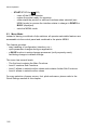
2.2.3 Meaning of the Keys in the LOCAL Mode
- Lower Row Keys
- Insert or Eject Key
(90)
After pressing the Insert/Eject key, fanfold paper from the park position
is fed into the print position, and fanfold paper from the print position is
fed into the cut/tear off position (depending on the setting or the printer
type). Paper that has been retracted into the cut/tear off by the
Insert/Eject key will be moved automatically into the print position once
the printer receives a print command.
Note:
This key is not active while the top cover is open.
- The Paper Feed Key
(91) and the
Reverse Paper Feed Key
(92)
The paper moves 1/90" (0.28 mm) in the direction of the arrows. Holding
down the key results in continuous feeding.
Forward movement of paper from the park position is stopped at the
print position. Forward movement of paper from the print position is
stopped at the tear off position or it will be cut off (depending of the
setting or of the printer type).
Backward movement of paper is stopped at either the park position, the
print position or the tear off position.
2-7
Printer Operation
- START/STOP Key
(93)
- turns off the STOP indicator
- makes the printer ready for operation
- either starts the printout or self-test functions when selected (see
MENU mode) or causes the interface status to change to READY or
BUSY (displayed)
- exits the MENU mode.
2.3 Menu Mode
Instead of having a multitude of dip switches, all operator selectable features are
accessable via the control panel and combined in the printer MENU.
This feature provides:
- easy handling of configuration (interface, etc.)
- quick parameter changes during an application
- a SAVE function to make changes permanent (until purposely reset),
facilitating changes in default settings.
The menu has several levels:
- The first level contains the Main Functions
- Level 2 contains Sub-Functions
- Level 3 allows to select/confirm values and contains further Sub-Functions
- Level 4 allows to select/confirm values
For easy selection of paper source, font, pitch and macro, please refer to the
Quick Settings section in this chapter.
2-8
Printer Operation
2.3.1 To Activate the Menu:
- Press
The printer is in the STOP mode, the display shows LOCAL
- Press
in the top row of the control panel. As soon as the menu mode has
been activated, the keys in the top row can only be used as cursor keys to
move within the menu tree (up, down, right, and left).
Selection within a level:
- press [[] or [\] key; the keys have a wrap around function, i.e. after the last
value the first value is repeated.
On the display you will find the following four characteristic types of information:
This display is only shown if you are in the Main Function. To switch to the next
level press [Y].
Now you are in a Sub-Function. Movement in both directions is possible by
using the [Z] key or [Y] key.
In the last level, labelled select/confirm values, the asterisk (’) to the right
indicates the actual selection.
By using the [[] or [\] key, you are able to select a new value. You get the
display:
2-9
Printer Operation
2.3.2 To Confirm Selection:
- press [Y]; the confirmed value is displayed with an asterisk (’) in the last
position as shown in the picture before.
Note:
All cursor keys have an auto repeat function.
The MENU mode is left either by pressing
or by moving to the MAIN
FUNCTION level and then pressing the [Z] key.
A number of VALUE settings is summarized in a "Macro". It is possible to have a
total of four macros, each with a different summary of VALUE settings. The
standard macros have the following emulations defined:
Macro
Emulation
1
EPSON LQ 1060, LQ 2550 / ESC/P2
2
IBM Proprinter XL 24
3
IBM Proprinter XL 24 AGM
4
EPSON LQ 1060, LQ 2550 / ESC/P2
Macro parameters can be tailored to specific application requirements. This
feature is highly beneficial in case of frequent changes between applications in
multi-user environment. Instead of having to adjust the menu settings each time
before a particular application is starting, the user simply selects the macro
containing the pre-defined set-up configurations.
2-10
Printer Operation
2.3.3 How to Save Settings
The settings selected and confirmed are only active until the printer is switched
off. In order to prevent losing your new settings you can save them using the
MAIN FUNCTION SAVE.
KEY
Display
1.
(93)
LOCAL
2.
(94)
MACRO SELECT
6
3. [[] -- [[]
SAVE
6
4. [Y]
SAVING NOW
(display is flashing)
’
4a.
SAVE
6
5.
Note:
(93)
READY
1 ELQ
The values of the "current settings" and the macro settings can be printed
out on a list using the function PRINT OUT.
MENU
aa
a a
abc
94
93
2-11
Printer Operation
2.3.4
Quick Settings
The keys
(94) (to select a pre-configured macro),
(95),
(96), and
(97) are shortcuts in the menu tree. These particular selections can be
changed quickly without having to move through the entire menu (see fold out of
structure diagram). As soon as one of the keys in the top row has been
activated, all four keys can only be used as cursor keys to move within the menu
tree ([[] up, [\] down, [Y] right, and [Z] left).
2-12
3 Configuring the Printer
3.1
What is Configuring
This chapter describes how to use the operator panel and menu settings to set
up or configure your so that the printer and your computer system can
communicate correctly with each other.
Communication between the two requires that both the computer operating
system and the printer have the same communication settings or features. The
most important of those are:
S protocol,
S baud rate,
S data bits,
S parity.
You may also need to change some of the printer's other features depending on
your hardware and application requirements, for example:
S paper handling
S text processing.
The MENU mode allows you to access the configuration memory. All settings of
the printer are stored in this memory and can be printed out on a list. The
possible settings are discussed in detail in the following pages.
The menu printout illustrates the actual printer set-up. The following steps show
which keys to use to start this printout.
3-1
Configuring the printer
KEY
Display
1. Switch the printer ON
READY
1 ELQ
2.
(93)
LOCAL
3.
(94)
MACRO SELECT 6
6
4. [[]
PRINT OUT
5. [Y]
7 PRINT OUT
6. [Y]
7 PRINT OUT
’
7 PRINT OUT
’
7.
(93)
After feeding paper from the defined paper source, the printer starts to print.
When printing is completed, the following message will be displayed:
7 PRINT OUT
8.
9.
(93)
READY
MENU
aa
aa
1 ELQ
abc
94
93
3-2
Configuring the printer
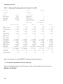
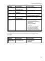
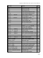
3.2 Standard Configuration
The standard configuration is reflected in the following printout provided that no
parameters have been changed.
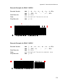
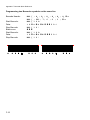
3.2.1
Standard Configuration for Printer CI - 4040
PRINT OUT
VERSION
INTERFACE
ADJUSTMENT
BUFFER
WORD LENGTH
I/F TYPE
BAUD-RATE
PARITY BIT
PROTOCOL
CTS MODE
8 KBYTE
8 BIT
PARALL./ RS232
9600 BPS
IGNORE
DTR
CTS IGNORE
20xxxxxx
AGC POSITION
PLATEN GAP
PAPER-IN ADJ.
CUT. V-POS
UNI-DIRECT.CMD
TRACT. FF-MODE
MENU ACCESS
CURRENT SETTINGS
FONT
PRINT QUALITY
GRAPHICS QUAL.
SUB/SUPER FONT
PITCH
LINE
PAGE LENGTH
TRACTOR V-POS
MANUAL V-POS
LEFT MARGIN
RIGHT MARGIN
TOP MARGIN
BOTTOM MARGIN
PERF. SKIP
PAPER SOURCE
PAPER EXIT
EMULATION
CHARACTER SET
LINE MODE
$$-COMMAND
TEAR-OFF-MODE
Note:
DATA
LQ
STANDARD
YES
10 CPI
6 LPI
72 LINES
0
0
1 COLUMNS
136 COLUMNS
1 LINES
1 LINES
YES
TRACTOR
BATCH
EPSON LQ
EPSON EXT.GCT
3: GERMANY
LF=LF, CR=CR
NO
NO
24
0
0
0
YES
IGNORE FF
*)
ALL FUNCTIONS
MACRO 1*
MACRO 2
MACRO 3
MACRO 4
DATA
LQ
STANDARD
YES
10 CPI
6 LPI
72 LINES
0
0
1 COLUMNS
136 COLUMNS
1 LINES
1 LINES
YES
TRACTOR
BATCH
EPSON LQ
EPSON EXT.GCT
3: GERMANY
LF=LF, CR=CR
NO
NO
DATA
LQ
STANDARD
YES
10 CPI
6 LPI
72 LINES
0
0
1 COLUMNS
136 COLUMNS
1 LINES
1 LINES
YES
TRACTOR
BATCH
IBM PROPR.
IBM SET 2
1: U.S.A.
LF=LF, CR=CR
NO
NO
DATA
LQ
STANDARD
YES
10 CPI
6 LPI
72 LINES
0
0
1 COLUMNS
136 COLUMNS
1 LINES
1 LINES
YES
TRACTOR
BATCH
IBM PROPR. AGM
IBM SET 2
1: U.S.A.
LF=LF, CR=CR
NO
NO
DATA
LQ
STANDARD
YES
10 CPI
6 LPI
72 LINES
0
0
1 COLUMNS
136 COLUMNS
1 LINES
1 LINES
YES
TRACTOR
BATCH
EPSON LQ
EPSON EXT. GCT
1: U.S.A.
LF=LF, CR=CR
NO
NO
An asterisk (’) after MAKRO 1 indicates the actual macro.
*) This value is dependent on factory setting!
All this standard settings of the firmware will be restored with the menu function
RECALL FACTORY.
3-3
Configuring the printer
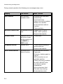
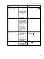
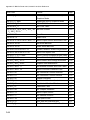
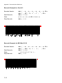
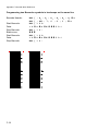
3.2.2
Standard Configuration for Printer CI - 4050
PRINT OUT
VERSION
INTERFACE
ADJUSTMENT
BUFFER
WORD LENGTH
I/F TYPE
BAUD-RATE
PARITY BIT
PROTOCOL
8 KBYTE
8 BIT
SHARED
9600 BPS
IGNORE
DTR
20xxxxxx
AGC POSITION
PLATEN GAP
PAPER-IN ADJ.
CUT. V-POS
UNI-DIRECT.CMD
TRACT. FF-MODE
MENU ACCESS
CURRENT SETTINGS
FONT
PRINT QUALITY
GRAPHICS QUAL.
SUB/SUPER FONT
PITCH
LINE
PAGE LENGTH
TRACTOR V-POS
MANUAL V-POS
BIN 1 V-POS
BIN 2 V-POS
BIN 3 V-POS
LEFT MARGIN
RIGHT MARGIN
TOP MARGIN
BOTTOM MARGIN
PERF. SKIP
PAPER SOURCE
PAPER EXIT
EMULATION
CHARACTER SET
LINE MODE
$$-COMMAND
TEAR-OFF-MODE
PRE-SEPARATION
Note:
DATA
LQ
STANDARD
YES
10 CPI
6 LPI
72 LINES
0
0
0
0
0
1 COLUMNS
136 COLUMNS
1 LINES
1 LINES
YES
TRACTOR
BATCH
EPSON LQ
EPSON EXT.GCT
3: GERMANY
LF=LF, CR=CR
NO
NO
NO
24
0
0
0
YES
IGNORE FF
*)
ALL FUNCTIONS
MACRO 1*
MACRO 2
MACRO 3
MACRO 4
DATA
LQ
STANDARD
YES
10 CPI
6 LPI
72 LINES
0
0
0
0
0
1 COLUMNS
136 COLUMNS
1 LINES
1 LINES
YES
TRACTOR
BATCH
EPSON LQ
EPSON EXT.GCT
3: GERMANY
LF=LF, CR=CR
NO
NO
NO
DATA
LQ
STANDARD
YES
10 CPI
6 LPI
72 LINES
0
0
0
0
0
1 COLUMNS
136 COLUMNS
1 LINES
1 LINES
YES
TRACTOR
BATCH
IBM PROPR.
IBM SET 2
1: U.S.A.
LF=LF, CR=CR
NO
NO
NO
DATA
LQ
STANDARD
YES
10 CPI
6 LPI
72 LINES
0
0
0
0
0
1 COLUMNS
136 COLUMNS
1 LINES
1 LINES
YES
TRACTOR
BATCH
IBM PROPR. AGM
IBM SET 2
1: U.S.A.
LF=LF, CR=CR
NO
NO
NO
DATA
LQ
STANDARD
YES
10 CPI
6 LPI
72 LINES
0
0
0
0
0
1 COLUMNS
136 COLUMNS
1 LINES
1 LINES
YES
TRACTOR
BATCH
EPSON LQ
EPSON EXT. GCT
1: U.S.A.
LF=LF, CR=CR
NO
NO
NO
An asterisk (’) after MAKRO 1 indicates the actual macro.
*) This value is dependent on factory setting!
All this standard settings of the firmware will be restored with the menu function
RECALL FACTORY.
3-4
Configuring the printer
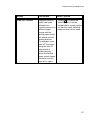
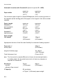
3.3 Explanation of the printouts on the previous pages
The heading PRINT OUT gives information about the VERSION of the printer's
firmware.
The next two headings are followed by two columns of standard settings:
S
INTERFACE - for communication between the computer operating system
and the printer it is necessary to have the same communication settings or
features. The standard settings are:
CI - 4040
CI - 4050
- 8 Kbyte buffer
- 8 Kbyte buffer
- 8 bit
- 8 bit
- parallel interface type
- shared interface type
- 9600 baud
- 9600 baud
- parity ignore
- parity ignore
- DTR protocol
- DTR protocol
- CTS ignore.
S ADJUSTMENT - all parameters are for adjustment of the printer and the
paper (see also the following pages).
The last part of the printout is a list with all MACRO settings. In this case
MACRO 1 is marked with an asterisk (’) which identifies it as the active macro.
If you make modifications in the active macro without saving them you will find
the new settings under the heading CURRENT SETTINGS. Unless they are
saved, the modifications will stay active only until the printer is switched off in
which case the macro settings marked with the asterisk will be reactivated.
3-5
Configuring the printer
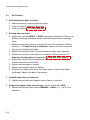
3.4
Explanation of Individual Menu Items
Main Functions
The following main functions are available:
S MACRO SELECT
To select one of the four macros which can be used for quickly changing the
printer settings for different applications. For example: Application A needs
fanfold paper cut into single sheets with a top margin of one, application B
processes fanfold paper in a batch with a top margin of six. Simply by
pressing MACRO SELECT the macro containing the information for the
specific application requirements can be activated.
S CHANGE MACRO
In this part it is possible to create a macro for specific application needs (For
detail information see chapter Function CHANGE MACRO beginning on the
next page).
Note:
Most parameters can be set via the control panel or via escape sequences
from the host computer. The changes via escape sequences are visible in
the column CURRENT SETTINGS
S INSTALLATION
In the first sub-function named INTERFACE you can manipulate parameters
to enable communication with the host.
In the second sub-function labelled ADJUSTMENT you can optimize your
printouts. (Detail information you will find in the Sub-Function INTERFACE /
ADJUSTMENT)
S SAVE
Any desired changes to the default settings can be saved here. After power
on the new settings are activated.
While this function is operating the display flashes SAVING NOW.
3-6
Configuring the printer
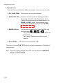
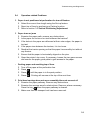
S PRINT OUT
This function initiates a printout of the parameter settings and macro
definitions. This printout is helpful for future reference and when macros are
to be changed.
To actually start the print operation it is necessary to leave the STOP mode
(by pressing the
key).
While this function is operating the display shows PRINT OUT.
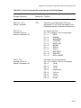
Main Function CHANGE MACRO
S Font
A font is a family of characters with the same style and size. The appearance
of the font can be varied by using attributes such as: size, bold, italic, etc.
The fonts included in the PM SER/PAR are:
S Data
S Roman
S San Serif
S Courier
S Prestige
S Script
S OCR B
S OCR A
S Orator-C
S Orator
S DATA LARGE
see Appendix B for print samples.
Note:
PRINT TEST 3 lists all available fonts. The firmware of the printer
indicates also barcodes. Detail information for printing barcodes are in
Appendix F Barcodes Quick Reference.
3-7
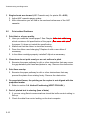
Configuring the printer
S Print Quality
Is splitted up into:
S Font Quality
Three different font quality levels can be selected:
S Draft quality (font "Data")
S Near letter quality (NLQ displayed with the font name)
S Letter quality (LQ displayed with the font name).
and
S Graphics Quality
Four different graphics quality levels can be selected:
S Standard
S Win. LQ 180 DPI
S Win. NLQ 90 DPI
S WI. Draft 60 DPI
Note:
Different print / graphics qualities result in different print speed.
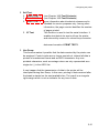
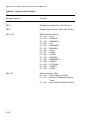
S Sub/Super Font
When the SUB/SUPER FONT is set to "NO", sub and superscript text will be
raised or lowered a half line, but the text size itself will not change.
When set to "YES", the text size will be reduced, and printed above or below
the line.
Example: YES
52 or 52
NO
52 or 52
S Pitch
Indicates the number of characters printed per inch (10, 12, 15, 17, 18, 20 or
proportional).
Any pitch setting can be combined with any available font. In some cases this
may conflict with font designs. The pitch setting is, therefore, a matter of
personal taste.
S Line
Determines the number of lines per inch (line space).
3-8
Configuring the printer
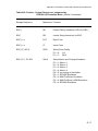
S Page Length (only for fanfold paper)
Page length is expressed in terms of lines within the range of 18 to 132 lines.
Any page length setting is based on six lines per inch, regardless of the
number of lines per inch selected in the line setting or defined by the
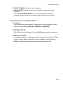
application.
The following indicates the number of lines for the most common paper sizes.
Paper length
in inches
4
4
6
8
8
11
11
12
1
/6
1
/2
2
/3
(default setting)
Appropriate setting
in no. of lines
24
25
36
48
51
66
70
72
The page length setting is the basis from which perforation skip, TEAR-OFF
mode and margins operate.
An incorrect page length, therefore, gives an incorrect perforation skip.
3-9
Configuring the printer
S Vertical Positioning Adjustment (VERT.POS.ADJ.)
This function changes the vertical position in the current macro for the five
different paper paths TRACTOR V-POS ,MANUAL V-POS or only for printer
CI - 4050 the BIN x V-POS (x = 1 up to 3) exactly position the printout in
relation to the top edge of the form in use. It is meant to be a corrective
parameter to meet variations in paper size and pre-printed material. Using this
function, the TOP MARGIN and BOTTOM MARGIN setting are taken into
account as well.
This parameter covers a range of - 15/60 to + 240/60 of an inch, where "-" is up
the page and "+" is further down the page.
The following table shows some values in inch and millimetres.
+/- 1
+/- 2
+/- 3
+/- 4
+/- 5
+/- 6
+/- 7
+/- 8
Attention:
=
=
=
=
=
=
=
=
+/- 1/60"
+/- 2/60"
+/- 3/60"
+/- 4/60"
+/- 5/60"
+/- 6/60"
+/- 7/60"
+/- 8/60"
=
=
=
=
=
=
=
=
+/- 0,42 mm
+/- 0,85 mm
+/- 1,27 mm
+/- 1,69 mm
+/- 2,12 mm
+/- 2,54 mm
+/- 2,96 mm
+/- 3,39 mm
+/- 9
+/- 10
+/- 11
+/- 12
+/- 13
+/- 14
+/- 15
+ 16
=
=
=
=
=
=
=
=
+/- 9/60"
+/- 10/60"
+/- 11/60"
+/- 12/60"
+/- 13/60"
+/- 14/60"
+/- 15/60"
+ 16/60"
=
=
=
=
=
=
=
=
+/- 3,81 mm
+/- 4,23 mm
+/- 4,66 mm
+/- 5,08 mm
+/- 5,50 mm
+/- 5,93 mm
+/- 6,35 mm
+ 6,77 mm
The set up of VERT.POS.ADJ. will become effective at the next page
of the form. Therefore, it is recommended to perform
VERT.POS.ADJ. set up as long as the paper is in the park position
and before starting the print job.
S The left margin is set in 1/10" steps, depending on the actual selection. The
first left margin position is 1/20" from the left edge of the paper which means
that the letter H in regular "Data" font would be positioned 1/20" from the left
edge of the paper. The left margin can be set to a maximum of 15/10".
3-10
Configuring the printer
S The right margin is set to print position 80, 132 or 136, always measured
from the position of the first possible, not actual, left margin setting.
The left margin setting is influenced by the physical setting of the left tractor.
The above specifications are only correct if the tractors are in the original
positions, i.e. the left perforation is aligned with the centre mark on the plastic
plate (distance between the marks is 1/10").
S The top margin indicates the first print line and is always set in steps of 1/6".
The position of the first margin is 1/6" from the top of the paper and indicates
the baseline of the letter H in upright "Data" font (see illustration).
The top margin can be set to a maximum of 16/6" down on the paper.
3-11
Configuring the printer
S The bottom margin indicates the last print line. Going beyond this margin
automatically initiates a form feed. The bottom margin is always set in steps
of 1/6".
The bottom margin can be set to a maximum of 8/6".
The above specifications are influenced by the settings in "Vertical Position"
(see section "V.POS" in this chapter).
S Perforation Skip
S If PERF. SKIP is set to YES the printer starts to print after specified top
margin and stops printing before the bottom Margin.
S
If PERF. SKIP is set to NO the printer ignored the top and bottom margin
and prints from the very first line to the very last. That means that on a
standard 11" paper 66 lines are available for printing.
S Paper Source
The printer offers three input possibilities:
S
TRACTOR (fanfold paper)
S
Manual (for printer CI - 4040 optional)
S
ASF cassettes (optional only for printer CI - 4050), they can be
accessed either individually or pooled in a specified sequence. Any
combination or cassettes can be selected (for detail the chapter 7 ASF
Cassettes).
A corrective factor for the vertical positioning of the paper can be applied to
each paper source and the Run-In-Sensor (see section VERT.POS.ADJ.).
Note:
3-12
Please refer to chapter 8, Technical Data, for detailed media
specifications.
Configuring the printer
S Paper Exit (only for single sheet paper)
Printer CI - 4040: the output will be done in the manual input path. It is
possible to choose between FRONT SIDE/KEY and
FRONT SIDE if the manual front insertion guide is
mounted.
Printer CI - 4050: it is possible to choose between STACKER, FRONT SIDE,
and FRONT SIDE/KEY (manual front insertion). The
desired paper exit can be selected via operator panel or
software.
Note:
If you choose the paper exit FRONT SIDE/KEY you have to confirm each
output with a keystroke on
. That is a useful option when using
automatic sheet feeding which could cause a paper jam. As opposed to
feeding automatically the ASF will only feed after a keystroke has been
received.
S Emulation
The emulation determines the set of commands available for the printer (see
Appendix D and E). You can activate the following emulations:
S EPSON LQ
S IBM PROPR.
S IBM PROPR.AGM
Note:
The selected Emulation will also be stored in the actual macro. With a
change of the macro (e.g. key
,
,
or
is pressed) it is
possible that the emulation will also be changed. Be careful: Do not
change the emulation within an application.
S Character Set
When selecting a character set it can be further specified by the
corresponding national variants.
Detailed print samples are found in Appendix B and the Character Set
Tables in Appendix C.
If a different macro is selected the default character set may change,
e.g. - IBM PROPR. emulation has the character set IBM SET 2 as default.
- EPSON emulation has the character set EPSON EXT.GCT as default.
3-13
Configuring the printer
S Line Mode
If LF = LF + CR is selected, the printer performs a carriage return (CR) for
every line feed (LF) received by the interface.
If CR = LF + CR is selected, the printer performs a line feed (LF) for every
carriage return (CR) received by the interface.
S $$ Commands
This function causes $$ either to be printed as $$ or to activate ESC
commands within an application.
If this function is set to YES the characters are interpreted by the printer in the
following way:
S $$ like ESC [
S $$/ like ESC.
S Tear-off-mode (only for fanfold paper)
There are four possible settings within this mode:
S NO
S YES 10 SEC.
S YES 1 SEC.
S NO, SPECIAL
The NO SPECIAL setting is to be used with critical forms which cannot
handle the return movement of the paper.
With the YES setting the printer waits for one ore ten seconds and, unless
further data is received, moves the paper to the first perforation after the text.
Regardless of this setting, whenever changing from fanfold to the manual
paper source, the printer will request the fanfold paper to be torn off or at the
setting NO SPECIAL to be removed before the paper is moved to the park
position.
S Pre-separation (is used for the ASF cassettes (printer CI - 4050) only)
During normal printing, a sheet of paper is not inserted from an ASF cassette
before the preceding sheet has been ejected. By selecting
PRE-SEPARATION = YES the sheets follow each other more closely, thereby
increasing the printer's throughput.
3-14
Configuring the printer
Main-Function INSTALLATION
S Sub-Function INTERFACE
S BUFFER
Buffer size in Kbyte. The maximum size is 48 Kbyte.
S WORD LENGTH
Length of the data to be transferred; values are 7 or 8 bit.
S I/F TYPE (Interface Type)
the following types are available:
CI - 4040
PARALLEL
PARALL./ RS232 (shared mode)
PARALL./ RS422 (shared mode)
CI - 4050
PARALLEL
SERIAL
SHARED
In case the Parall/ RS232, Parall./ RS422; or SHARED mode" interface
type is selected the printer switches automatically between the parallel and
serial interfaces. The first data received at the port determine which
interface port becomes active. The other interface port will be closed so
that only one interface is active at a time (for detailed information see
Appendix A Interface Description).
The factory setting for the interface type are: Shared, 8 Kbyte Buffer, 8 bit
word length, even parity bit, 9600 baud rate, DTR protocol and ignore CTS.
S BAUD RATE (Only indicated if the serial interface is selected)
Controls the speed of data transfer. The possible transfer rates are: 600,
1200, 2400, 4800, 9600 or 19200 bps.
S PARITY BIT (Only indicated if the serial interface is selected)
The data transfer will be checked by an even or odd parity bit. The values
are: EVEN, ODD, NONE or IGNORE.
3-15
Configuring the printer
S PROTOCOL (Only indicated if the serial interface is selected)
Selectable are: DTR, XON/XOFF, or XON/XOFF + DTR.
S CTS MODUS (CI - 4040, only indicated if the serial interface is selected)
The input signal CTS (Clear To Send) of the RS232-C interface can be set
to ignore. The printer will send immediately data to the system.
S Sub-Function ADJUSTMENT
S AGC Position
AGC (Automatic Gap Control) is an integral part of the paper handling
capabilities of the printer. It is an automatic adjustment function which
ensures an optimal print quality when using various paper thicknesses.
The gap adjustment will automatically take place whenever paper is
inserted
S after the paper source has been changed
S from park position (fanfold)
S after Power On
S after the printer has been in the STOP mode
S an AGC command has been issued.
The reference point for the measurement of the paper thickness is the
AGC Position of the first print line. Default for the horizontal AGC Position
is 24 (= ink ribbon exchange position), any position from 4 to 131 (at 10
cpi) can be selected.
An adjustment of the AGC Position is only necessary if a measurement at
the default position does not reflect the paper thickness of the area to be
printed on or if there is a paper edge (e.g. of a label) in that position (the
measuring process requires a plain paper-surface).
In addition to the automatic AGC function, random measurements of the
paper thickness can be invoked by the AGC command, or a specific platen
gap can be set using the PCC command. This is to meet the requirements
of forms with complex properties. For details see the Programmers Manual
for the printer.
3-16
Configuring the printer
S Platen Gap
This adjustment is to be seen as a correctional offset to the platen gap set
by the AGC (Automatic Gap Control) function or a PCC (Programmable
Copy Control) command. It effects all paper paths.
The offset is within the range of -3 to +4. One step is equal to 18 µm.
"-" reduces the gap, "+" increases it.
S AGC Adjust
This is a basic adjustment which is automatically performed at the initial
Power On of the printer, and which there after only needs to be initiated
after having exchanged the print head or the platen. It is essential that the
ink ribbon is installed and no paper is in the printer when this procedure is
started. After activating this procedure, the printer displays
INSTALL RIBBON. If the ribbon is installed press
to continue.
S PAPER-IN ADJ (Paper-In-Sensor adjustment)
This parameter logically adjusts the base position of the Run-In-Sensor.
The factory set value is such that the default is set to compensate specific
mechanical tolerances. The adjustment range is from -3 to +4 in 1/60" steps
(0.42 mm), where "-" means an upward movement and "+" a downward
movement. When implemented, the adjustment applies to all paper paths.
3-17
Configuring the printer
S CUTTING V-POS
This parameter can be used to compensate mechanical tolerances which
may cause a misalignment between the perforation edge of a continuous
form and the tear-off position as well as the cutting position, in case the
cutting option is installed.
If no cutting device is mounted the value of CUTTING V-POS will influence
the TEAR-OFF Position.
The range within which variations can be met is - 15/60" to + 16/60", where "-"
is up the page and "+" is further down the page.
The following table shows the possible values in inch and millimetres.
Note:
If, for some reason, it is not desired to cut exactly on the perforation it is
very important to cut below the perforation of the printed page. If the
paper is cut above the perforation the remaining paper can easily bend and
cause a paper jam. Do not cut through a label as the blade would get dirty
by the glue.
+/- 1
+/- 2
+/- 3
+/- 4
+/- 5
+/- 6
+/- 7
+/- 8
=
=
=
=
=
=
=
=
+/- 1/60"
+/- 2/60"
+/- 3/60"
+/- 4/60"
+/- 5/60"
+/- 6/60"
+/- 7/60"
+/- 8/60"
=
=
=
=
=
=
=
=
+/- 0,42 mm
+/- 0,85 mm
+/- 1,27 mm
+/- 1,69 mm
+/- 2,12 mm
+/- 2,54 mm
+/- 2,96 mm
+/- 3,39 mm
+/- 9
+/- 10
+/- 11
+/- 12
+/- 13
+/- 14
+/- 15
+ 16
=
=
=
=
=
=
=
=
+/- 9/60"
+/- 10/60"
+/- 11/60"
+/- 12/60"
+/- 13/60"
+/- 14/60"
+/- 15/60"
+ 16/60"
=
=
=
=
=
=
=
=
+/- 3,81 mm
+/- 4,23 mm
+/- 4,66 mm
+/- 5,08 mm
+/- 5,50 mm
+/- 5,93 mm
+/- 6,35 mm
+ 6,77 mm
S Uni-Direct.CMD
If NO is selected, commands for uni-directional printing will be ignored. The
default setting of YES means that commands will be carried out to switch
from bi-directional to uni-directional or vice versa.
3-18
Configuring the printer
S TRACT.FF-MODE (Tractor Form Feed Mode)
BLANK PAGES means, every Form Feed sent to the printer will be
executed.
If you set NO BLANK PAGES, only a Form Feed before printable
characters will be executed, that means blank pages will be ignored.
Special Sub-Items under INSTALLATION
S Language
The operator panel may display its messages in three languages. Select
one out of the following: ENGLISH, DEUTSCH, FRANCAIS.
S RESTORE SET UP
With this function all settings of the last SAVE procedure will be restored.
S RECALL FACTORY
All standard settings of the firmware will be restored. The contents of Page
Counter and the Paper-in Adjust will not be changed. Use the function
SAVE if the standard settings shall be active after power off/on.
3-19
Configuring the printer
S Menu Access
There are four possibilities to define the access to the menu by the user.
S ALL FUNCTIONS
All functions can be used (default)
S QUICK SET. OFF
With this function the Quick Settings for Macro
Selection, Vertical Position Adjustment, and
Fanfold Displacement can be deactivated in the
READY or BUSY mode. After pressing one of
these keys the display shows shortly LOCKED
(see also Chapter 2).
S MACROS ONLY -
Macros can be selected using the Quick Macro
Selection keys
,
,
, or
.
- The Vertical Positioning Adjustment Mode can
be entered
- The Fanfold Displacement Mode can be
entered.
S NO ACCESS
The menu is not accessible at all.
The menu function PRINT OUT can be activated regardless of the defined
menu access.
Note:
3-20
Only the system manager is able to reset the functions MACROS
ONLY and NO ACCESS.
Configuring the printer
S
Self Test
S PRINT TEST 1
S PRINT TEST 2
S PRINT TEST 3
S
I/F Test
(see Chapter 1.12 Test Printouts)
(see Chapter 1.12 Test Printouts)
gives information about technical releases and is
intended for service purposes only. Among other
information, the page counter identifies the number
of pages printed.
This function is used to test the serial interface. It
enables test data to be sent out from the printer
and returned by means of a closed loop connector
data used consists of PRINT TEST 1.
S
Hex Dump
This function makes it possible that the data received by the printer can
be analyzed. Control codes are no longer carried out, instead all data is
printed in hexadecimal format and as ASCII characters. Any non-printable characters, such as carriage return are only represented as a
single dot (.) in the ASCII list.
It may happen that the transmission of data to the printer will be
interrupted during Hex Dump. In this case, printing of data received after
the break is started on the next available line. The result is an irregular
right margin which is not an indicator for any loss of data.
3-21
[MACRO SELECT
\
*
*
*
*
6]
))) [7 MACRO 1
[7 MACRO 2
[7 MACRO 3
[7 MACRO 4
*]
]
]
]
[
[CHANGE MACRO #
6] ))) [7 FONT
(# indicates the actually selected
\
macro, e.g. CHANGE MACRO 1)
*
\
*
*
*
*
*
*
*
*
*
*
*
*
*
*
*
*
*
*
*
*
*
*
*
*
*
*
*
*
*
*
*
*
*
*
*
*
*
*
*
*
*
*
*
*
*
*
*
*
*
*
*
*
*
*
*
*
*
*
*
*
*
*
*
*
*
*
*
*
*
*
*
*
*
*
*
*
[7 PRINT QUALITY
6]
[7 ROMAN
[7 SAN SERIF
[7 COURIER
[7 PRESTIGE
[7 SCRIPT
[7 OCR B
[7 OCR A
[7 ORATOR-C
[7 ORATOR
[7 DATA LARGE
6]
*
*
*
*
*
*
*
[7 PITCH
*
*
*
*
*
*
*
[7 LINE
*
*
*
*
*
*
*
[7 PAGE LENGTH
*
*
[7 VERT.POS.ADJ.
*
*
*
*
*
*
*
*
*
*
*
[7 LEFT MARGIN
*
*
[7 RIGHT MARGIN
*
*
*
[7 TOP MARGIN
*
*
6]
B
E
E
E PRINT QUAL.
C LQ or NLQ
E
E
D
)))) [7 LQ
*]
]
6]
)))) [7 STANDARD
*]
]
]
]
[7WIN.LQ 180 DPI
[7WIN.NLQ 90 DPI
[7WIN.DRAFT 60 DPI
))) [7 NO
[7 YES
6]
))) [7 10 CPI
[7 12 CPI
[7 15 CPI
[7 17 CPI
[7 18 CPI
[7 20 CPI
[7 PROPORTIONAL
6]
))) [7 6 LPI
[7 8 LPI
[7 12 LPI
[7 2 LPI
[7 3 LPI
[7 4 LPI
6]
))) [7 72 LINES
6]
))) [7 TRACTOR V-POS
*
6]
*]
]
*]
]
]
]
]
]
]
*]
]
]
]
]
]
*]
(tractor only; range: 5..132 lines)
6]
6]
))) [7 1 COLUMNS
))) [7 136 COLUMNS
[7 80 COLUMNS
[7 132 COLUMNS
6]
*]
))) [7 1 LINES
*]
]
]
*]
(range: 1...16 lines)
))) [7 1 LINES
*]
(range: 1...8 lines)
6]
))
[7 TRACTOR V
(range: -15...+240)
[7 MANUAL V-POS
6] ))
[7 MANUAL V
*
(range: -15...+16)
[7 BIN 1 V-POS
6] ))
[7 BIN 1 V
*
(range: -15...+16)
[7 BIN 2 V-POS
6] ))
[7 BIN 2 V
*
(range: -15...+16)
[7 BIN 3 V-POS
6] ))
[7 BIN 3 V
(range: -15...+16)
Note: Bins are only options for printer CI - 4050
(range: 1..16 columns)
[7 BOTTOM MARGIN 6]
[7 PERF. SKIP
))) [7 FONT QUALITY
[7 GRAPHICS QUAL
*
*
*
*
*]
LQ/NLQ ]
LQ/NLQ ]
LQ/NLQ ]
LQ/NLQ ]
LQ/NLQ ]
LQ ]
LQ ]
LQ/NLQ ]
LQ/NLQ ]
]
[7 NLQ
[7 SUB/SUPER FONT 6]
*
*
*
))) [7 DATA
))) [7 YES
[7 NO
*]
]
0
*]
0
*]
0
*]
0
*]
0
*]
*
*
*
*
*
*
*
*
*
*
*
*
*
*
*
*
*
*
*
*
*
*
*
*
*
*
*
*
*
*
*
*
*
*
*
*
*
*
*
*
*
*
*
*
*
*
*
*
*
*
*
*
*
*
*
*
*
*
*
*
*
*
*
*
*
*
*
*
*
*
*
*
*
*
*
*
*
*
*
*
*
*
*
*
[7 PAPER SOURCE
*
*
*
*
*
*
*
*
[7 PAPER EXIT
*
*
*
*
[7 EMULATION
*
*
*
*
*
6]
*]
]
]
]
]
]
]
]
Bins are only options for
printer CI - 4050
*]
]
]
Stacker is only for pinter CI - 4050
(with START/STOP Key)
(without START/STOP Key)
*]
]
]
]
(Macro 1)
(Macro 2)
(Macro 3)
(Macro 4)
6]
)))
[7 1: U.S.A.
[7 2: FRANCE
[7 3: GERMANY
[7 4: U.K.
[7 5: DENMARK
[7 6: SWEDEN
[7 7: ITALY
[7 8: SPAIN
[7 9: JAPAN
[7 10: NORWAY
[7 11: DENMARK 2
[7 12: SPAIN 2
[7 13: LATIN AM.
[7 14: TURKEY
[7 15: LEGAL
*]
]
*]
]
]
]
]
]
]
]
]
]
]
]
]
6]
)))
[7 1: CP 437 GK
[7 2: CP 851 GK
[7 3: CP 928 GK
[7 4: CP 855 CYRI
[7 5: CP 866
[7 6: CP 869
[7 7: CP 852
[7 8: KAMENICKY
[7 9: ISO LATIN 2
[7 10: MAZOVIA
[7 11: CP 437 HUN
[7 12: CP 852 SEE
[7 13: CP 866 LAT
[7 14: WIN LAT 2
*]
]
]
]
]
]
]
]
]
]
]
]
]
]
6]
)))
[7
[7
[7
[7
[7
1: CP 771
2: CP 773
3: CP 774
4: CP 775
5: BALTIC RIM
*]
]
]
]
]
[7 IBM SET 1
6]
[7 IBM SET 2
6]
* (Macro 2, 3)
)))
[7 1: U.S.A.
[7 2: FRANCE
[7 3: GERMANY
[7 4: U.K.
[7 5: DENMARK
[7 6: SWEDEN
[7 7: ITALY
[7 8: SPAIN
[7 9: JAPAN
[7 10: NORWAY
[7 11: DENMARK 2
[7 12: SPAIN 2
[7 13: LATIN AM.
[7 14: TURKEY
*]
]
]
]
]
]
]
]
]
]
]
]
]
]
)))
[7 1: PAGE 437
[7 2: PAGE 850
[7 3: PAGE 860
[7 4: PAGE 863
[7 5: PAGE 865
[7 6: PAGE 858
*]
]
]
]
]
]
[7 MANUAL
[7 BIN 1
[7 BIN 2
[7 BIN 3
[7 BINS 1/2
(pools)
[7 BINS 2/3
(pools)
[7 BINS 1/2/3 (pools)
6]
))) [7 STACKER
[7 FRONT SIDE/KEY
[7 FRONT SIDE
6]
[7 CHARACTER SET 6]
*
*
*
*
*
*
*
*
*
*
*
*
*
*
*
*
*
*
*
*
*
*
*
*
*
*
*
*
*
*
*
*
*
*
*
*
*
*
*
*
*
*
*
*
*
*
*
*
*
*
*
*
*
*
*
*
*
*
*
*
*
))) [7 TRACTOR
))) [7 EPSON LQ
[7 IBM PROPR.
[7 IBM PROPR. AGM
[7 EPSON LQ
))) [7 EPSON EXT. GCT
*
Option for printer CI - 4040
(Macro 1 = GERMANY)
(Macro 4 = U.S.A.)
*
*
*
*
*
*
*
*
*
*
*
*
[7CODE PAGE EE
*
*
*
*
*
*
*
*
*
*
*
*
*
*
[7CODE PAGE EE2
*
*
*
*
*
*
*
*
*
*
*
*
*
*
*
*
*
*
[
[7 IBM CODE PAGE
6]
*
*
*
*
*
*
*
*
*
*
*
*
*
*
*
*
*
*
*
*
*
[
[INSTALLATION
\
*
*
*
*
*
*
*
*
*
*
*
*
*
*
*
*
*
*
*
*
*
*
*
*
*
*
*
*
*
*
*
*
*
*
*
*
*
*
*
*
*
*
*
*
*
*
*
*
*
*
*
*
*
*
*
*
*
*
*
*
*
*
[7 LINE MODE
*
*
*
*
[7 $$ COMMAND
6]
))) [7 LF=LF, CR=CR
[7 LF=LF+CR
[7 CR=LF+CR
[7 LF, CR=LF+CR
6]
*
*
))) [7 NO
*]
]
[7 YES
[7 TEAR-OFF-MODE 6]
*
*
*
))) [7 NO
[7 YES 10 SEC
[7 YES 1 SEC
[7 NO, SPECIAL
[
[7 PRE-SEPARATION 6]
))) [7 NO
[7 YES
6]
))) [7 INTERFACE
\
*
*
*
*
*
*
*
*CI - 4040
*
*
*
*CI - 4050
*
*
*
*
*
*
*
*
*
*
*
*
*
*
*
*
*
*
*
*CI - 4040
*
*
*
*
*
[7 ADJUSTMENT
*
*
*
*
*
*
*
*
*
*
*
*
*
*
*
*
*
*
*
*
*
*
6]
))) [7 BUFFER
\
*
*
*
*
[7 WORD LENGTH
*
*
[7 I/F TYPE
*
*
*
[7 I/F TYPE
*
*
*
1)
[7 BAUD RATE
*
*
*
*
*
*
1)
[7 PARITY BIT
*
*
*
*
1)
[7 PROTOCOL
*
*
*
1)
*]
]
]
]
[7 CTS MODE
*]
]
]
]
(only for Printer CI - 4050)
*]
]
(only for Printer CI - 4050
bins 1..3 only)
6]
)))) [7 8 KBYTE
6]
)))) [7 8 BIT
6]
)))) [7 PARALL./ RS232
6]
6]
)))) [7 SHARED
),
*
*
*
.)
[7 600 BPS
[7 1200 BPS
[7 2400 BPS
[7 4800 BPS
[7 9600 BPS
[7 19200 BPS
]
]
]
]
*]
]
[7 IGNORED
[7 ODD
[7 NONE
[7 EVEN
*]
]
]
]
6]
)))
[7 DTR
[7 XON/XOFF
[7 XON/XOFF + DTR
*]
]
]
6]
)))
[7 CTS IGNORE
[7 CTS ACTIVE
*]
]
6]
)))
[7 POSITION 24
(range: 4...131)
*]
6]
)))
[7 PLATEN GAP 0
(range: -3...+4)
*]
6]
)))
6]
)))
[7 PAPER-IN
(range: -3...+4)
0
*]
6]
)))
[7 CUTTER V
(range: -15...+16)
0
*]
6]
)))
[7 YES
[7 NO
*]
]
6]
)))
[7 NO BLANK PAGES
[7 BLANK PAGES
*]
]
))) [7 AGC POSITION
[7 AGC ADJUST
*]
]
]
)))
6]
*
*
[7 PARALLEL
[7 SERIAL
6]
only indicated if SERIAL is selected
*
*]
]
]
[7 PARALL./ RS422
[7 PARALLEL
1)
[7 PLATEN GAP
*]
]
[7 7 BIT
*
\
*]
*]
]
]
]
[7 16 KBYTE
[7 32 KBYTE
[7 48 KBYTE
[7 1 KBYTE
[7 NO
[7 YES
(parameter [YES] gives the message [INSTALL RIBBON] ;
after check press
)
*]
]
*
*
[7 PAPER-IN ADJ.
*
*
[7 CUTTING V-POS
*
*
[7 UNI DIRECT.CMD
*
[
[7 TRACT. FF-MOD
*
*
*
*
*
*
*
*
*
*
*
*
*
*
*
*
*
*
*
*
*
*
*
*
*
*
*
*
*
[7 LANGUAGE
6]
*
*
*
*
[7 DEUTSCH
[7 FRANCAIS
[7 RESTORE SET UP 6]
*
*
*
[7 MENU ACCESS
*
*
*
*
*
[7 SELF TEST
6]
\
6]
))) [7 PRINT TEST 1
[7 PRINT TEST 2
[7 PRINT TEST 3
[7 I/F TEST
[
6]
6]
))) [7 SAVING NOW
]
6]
))) [7 PRINT OUT
]
*
[
[PRINT OUT
))) [7 ALL FUNCTIONS
[7 QUICK SET OFF
[7 MACROS ONLY
[7 NO ACCESS
[
[SAVE
))) [7 NO
[7 YES
*
*
*
[7 HEX DUMP
))) [7 NO
[7 YES
[7 RECALL FACTORY 6]
*
*
*
))) [7 ENGLISH
))) [7 HEX DUMP
*]
]
]
*]
]
*]
]
*]
]
]
]
]
]
]
]
]
(only Serial Interface)
4. Maintenance
Preferred Materials
The following materials and cleaning lubricants are recommended for use in the
maintenance procedure:
S
S
S
Lint-free cloth
Platen Cleaner C/CP09, commercial no: 8709 004 10931
Vacuum cleaner.
4.1
Cleaning the Platen and Surrounding Areas
The user should clean the printer every six months or after 50,000 prints,
whichever occurs first. If you experience paper feed problems, or if the print
head carriage movement becomes restricted, cleaning should be carried out
more often.
Note:
the Page Counter (PGCNT) in the PRINT-TEST 3 will give you
information about actual number of printed pages. (See sample next
page.)
4-1
Maintenance
PRINT TEST3
CONFIGURATION
PM1
SPC
MCR
20808xxx
2080740x
0
NFQ
TNA1
PTC1
PHCS2
PM2
MC
1800
230
2.75
1.00
00000000
00000000
DSF
TNA2
PTC2
PGC
100
260
2.85
30
PM3
CUR
20807xxx
4
GSF
TNA3
PTDT
PGCNT
PBC
PMR
70
260
5
333
20807xxx
0
NTF
CAC
PHCS1
SBP
240
3.10
2.20
25
C061 IBM SET 1
C071 EPSON EXT. GCT
C091 BARCODE
C062 IBM SET 2
C100 CODE PAGES EE
C063 IBM CODE PAGE
C101 CODE PAGES EE2
DATA
SAN SERIF
COURIER
SCRIPT
OCR A
ORATOR
ROMAN
SAN SERIF
PRESTIGE
SCRIPT
ORATOR-C
ORATOR
ROMAN
COURIER
PRESTIGE
OCR B
ORATOR-C
DATA LARGE
NLQ
LQ
NLQ
LQ
NLQ
CHARACTER SET
AGC TEST
:
NLQ
LQ
NLQ
LQ
NLQ
LQ
EPSON EXT. GCT
AGC TEST
LQ
NLQ
LQ
LQ
LQ
3: GERMANY
AGC TEST
AGC TEST
AGC TEST
PRINTHEAD NEEDLE
1
2
3
4
5
6
7
8
9
10
11
12
13
14
15
16
17
18
19
20
21
22
23
DATA
!"#$%&'()*+,-./01234567890:;<=>?.......
.
.
Note:
4-2
The number following PM1 identifies the micro program and the number
following PM3 identifies the character set.
24
Maintenance
4.2
Cleaning Procedure
1. Power the printer ON and remove the top cover.
2. Remove the ribbon cassette.
3. Thoroughly brush and vacuum all accessible areas to remove any paper flock
and dust.
4. Clean the platen's surface, the paper pressure rollers and the transport rollers
using the platen cleaner. In order to access the transport rollers loosen the
green screws and remove the metal bar with the metal rollers.
5. Clean the covers and the operator panel with a damp, lint-free cloth. Do not
use cleaning solvents or excessive amounts of water.
6. Insert the ribbon cassette (see Chapter 1.8 Installing the Black Ribbon
Cassette).
7. Remount the top cover.
4-3
Maintenance
4.3
User Replaceable Parts
Replacement of the Print Head
The print head has an expected life time of approximately 350,000 pages (see
Page Counter (PGCNT in PRINT TEST 3).
Print Head Removal
Caution:
The print head may be very hot immediately after printing.
1. Remove theoutput stacker (1) (only for printer CI - 4050).
2. Switch the printer ON, lift and remove the top cover (2). The print head will
move to the correct position, aligned with the cut-out in the paper guide plate.
3. Switch the printer OFF again.
4. Remove the ribbon cassette (3).
5. Disconnect the print head cable (4).
6. Using the supplied tool (7)., loosen the two captive screws (6) retaining the
print head (5). Use the enclosed plastic case as an extension for the socket
head cap key
7. Remove the print head (5).
4-4
Maintenance
Print Head Installation
Ensure that the printer is switched OFF. For print head installation, the carriage
should be aligned with the cut-out in the paper guide plate (same position as for
removal procedure).
1. Hold the print head (5) in its mounting position and press it against its stop in
direction of the platen. The two noses (9) of the adjustment guide (8) support
this procedure.
2. Fasten the captive screws (6):
- fasten the right screw to its stop
- tighten the left screw
- now tighten the right screw
- put the enclosed plastic case onto
the socket head cap key and first
tighten the right and then the left screw.
6
8
3. Reconnect the print head cable (4) and fasten it.
4. Mount and close the top cover (2) and only for printer
CI - 4050 the output stacker (1).
9
5. Switch the printer ON, open the top cover after the message
READY 4 ELQ, and insert the ink ribbon cassette.
6. Run the MENU-function AGC ADJUST with ribbon cassette installed but
without any paper inserted in the printer.
4-5
Maintenance
Replacement of the Platen
The platen needs to be replaced after approximately 800,000 pages (see Page
Counter (PGCNT) in PRINT TEST 3).
To Remove the Platen (2)
1. Remove the output stacker (only printer CI - 4050).
2. Lift and remove the top cover.
3. Remove the ribbon cassette.
4. Switch the printer OFF.
5. Position the print head to the very right.
6. Release the green plastic platen clamp (1) on the left platen mounting.
7. Move platen (2) approximately 10 mm to the left, lift the left end of the platen
free off its mounting and withdraw the platen from the right mounting.
8. Lift the platen to the left underneath the print head and take it out.
4-6
Maintenance
To Install the Platen
Ensure that the printer is switched OFF.
1. Place platen (2) in the vacant space between print head and metal bar.
2. Move print head from its right hand position into the centre.
3. Fit the gear wheel end of the platen into the right hand side mounting. Be
careful not to damage the gear wheel.
4. Ensure that the plastic platen clamp (1) is in the upright position, push the
platen in to its mounting and lock in position by pushing the tag on the clamp
to the rear.
5. Install the ribbon cassette.
6. Fit and close the top cover.
7. Fit the output stacker stacker (only printer CI - 4050).
8. Run the MENU-function AGC ADJUST with ink ribbon cassette installed but
no paper inserted.
4-7
5. Troubleshooting and Diagnostics
How to Use This Section
1. Find the category in which your problem occurs. The problem categories are:
S Power-related Problems
S Error Messages
S No Printout
S Operation-related Problems
S Print-related Problems
S Ribbon or Carriage-related Problems
For example, if the print appears very light on the paper, look at Section "Printrelated Problems".
2. Find the symptom description that most closely matches the printer
symptom. In this example you would look at the symptom "Print faint or
of poor quality."
3. Try the first suggestion under that heading.
4. If the suggestion does not cure the problem, try the next suggestion.
5. If none of the suggestions enable you to continue printing, or if the fault is
not listed, contact your service office.
Each time the printer is switched ON the display indicates TEST while the
internal self-tests are run. If the test is completed successfully READY 1 ELQ
will be displayed. If an error message is displayed please refer to the following
section.
5-1
Troubleshooting and Diagnostics
5.1
S
S
Power-related Problems
Power indicator does not come On when power is switched On
Check that the power cord and plug are securely fitted to the printer and to
an electrical outlet.
Ask for the power connector connections (and fuse, if fitted) to be verified.
Ask for the building electrical supply to be verified.
S
S
5.2
Error Messages
After switching the power ON the printer runs a self test. During the test the
following messages may be shown on the display:
Display
That means ...
Cause / Action
No
information,
POWER ON
indicator not
lit.
No power
- Mains cable not connected
green and
yellow LED
give light but
no reaction
hang up in reset after
power on
- Print PSU defective
- Print CU-DEV defective
$$$$$$$$$
Firmware does not
work
- PM not inserted
- PM not correctly inserted
- no firmware on PM
- PROMs not correctly installed
TEST....
(flashing)
Initializing of the
EEPROM
- After first POWER ON
with PM
- Change of the PM
- Contents of the EEPROM
faulty
I/O OK
EEPROM located on
the Control Unit not
addressable
EEPROM
- not installed
- not correctly installed
- defective
5-2
Troubleshooting and Diagnostics
Display
That means ...
Cause / Action
NV RAM OK
Error on the RAM of
the Control Unit
- Control Unit defective
RAM OK
Checksum error
(P)ROM 1
- (P)ROM defective
ROM 1 OK
No Fonts available
- Character generator P(ROM)
on PM damaged or missing
ROM 2 OK
RAM on Memory
Card damaged
- Memory Card defective
MC OK
Fault on Control Unit
- Control Unit defective
- Type mismatch of PM and
Control Unit
- PBC (Printer Base
Controller)
on Control Unit damaged
- SPC (Speed Controller)
on Control Unit damaged
- Transport lock not removed
If all tests have been passed successfully the following message will be
displayed:
Display
That means...
Cause / Action
READY/BUSY
The Printer is OK
- Printer ready for
operation
5-3
Troubleshooting and Diagnostics
During normal operation the following error messages may occur:
Display
That means...
Cause / Action
AGC ERROR
AGC ADJUST
procedure fault
- Distance print head and
platen faulty
- Print head loose
- Platen incorrectly installed
- Ribbon not inserted
- Horizontal drive without
function
- Platen got dirty
BUFFER OVERFLOW
Handshake protocol - Check CTR - CTS or
error
XON - XOFF protocol
- Repeat data transfer
COVER OPEN
Displayed when the - Close cover
top cover is open
and the printer is in
the READY or
BUSY mode.
FRAMING ERROR
Protocol error
- Check protocol setting of
printer and host
- Repeat data transfer
HOR. DRIVE ERROR
Horizontal drive
without function
- Horizontal drive blocked
- Paper jam
- Distance of platen gap too
narrow
- AGC procedure on not
workable position
- Platen incorrectly installed
- No AGC ADJUST after
print head or platen
replacement
- Device electronic fault
- Encoder strip missing
- Horizontal drive fault
5-4
Troubleshooting and Diagnostics
Display
That means...
Cause / Action
LOAD BIN (only for
printer CI - 4050)
Displayed whenever - Load paper and press
a form feed
command or print
command is given
by the host to an
empty ASF
cassette. The
printer enters the
STOP mode.
LOAD MANUAL
Same as LOAD
- Insert paper
TRACTOR except
that the machine
does not enter the
STOP mode! Paper
should be fed
manually; after a
short delay the
printer will accept
paper and starts
printing.
LOAD TRACTOR
Displayed when the - Load fanfold into the tractor
host sends a form
and press
.
feed or print
command to an
empty tractor
cassette. The
printer enters the
STOP mode.
LOCAL
Entered when
- Press
was pressed. The
STOP indicator is lit.
.
to continue.
5-5
Troubleshooting and Diagnostics
Display
That means...
PAPER JAM TRF
PAPER JAM ASF (only
for printer CI - 4050)
PAPER JAM MANUAL
Displayed if a form - Please refer to paragraph
jams in the ASF or if 5.4 for suggestions how to
successive line
remove a paper jam.
feeds fail to move
fanfold paper
correctly when
tractor feed is used.
PARITY ERROR
Protocol error
REMOVE PAPER
This message will
- Remove paper and press
be displayed if the
.
output for cut sheets
(Bin or Manual) is
selected to FRONT
SIDE/KEY.
(for CI - 4040 is
front side the
standard option)
After printing and
moving out at the
front side the printer
enters the STOP
mode and displays
REMOVE PAPER.
5-6
Cause / Action
- Check protocol setting of
printer and host
- Repeat data transfer
Troubleshooting and Diagnostics
Display
That means...
Cause / Action
TEAR OFF PAPER
Displayed when a
- Press
to enable the
switch has been
fanfold paper to be fed
initiated from
backwards to a park position
currently tractor to a so that the newly selected
different paper
paper source can be used.
source and the
fanfold paper could
not retreat into the
parking position.
The operator must
"tear off" the paper
along the tear off
edge which is
located directly
above the fanfold
paper output (paper
should be torn off
from left to right).
5-7
Troubleshooting and Diagnostics
5.3
No Printout
S
Self-test printout does not start
S Make sure that you have closed the cover.
S Check if paper is loaded in the printer.
S Refer to section 1.12 Test Printouts.
S
Printing does not start
S Make sure that the READY or BUSY message is displayed. If there is a
different message displayed please refer to the above error message
table.
S Make sure that the printer is connected to the host computer. (Refer to
Section 1.13 Connection to a Computer). Make sure that connectors
are properly fixed at both ends.
S Make sure that the printer is receiving data from the host computer.
S Make sure that the correct protocol is enabled. (Refer to section 3.2
Standard Configuration and Appendix A Interface Description).
S Make sure that you have selected the correct port (if the automatic
feature has not been selected).
S Make sure that paper is loaded.
S Make sure that the ribbon is installed.
S Examine the ribbon path. Does the ribbon pass in front of the whole
printhead? Adjust the ribbon if necessary.
S
Fanfold paper does not advance
S Make sure that the fanfold paper source tractor is selected.
S
Single sheet paper does not advance (only for Printer CI - 4050)
S Make sure that the paper source MANUAL or BIN x (x = 1 up to 3) is
selected.
5-8
Troubleshooting and Diagnostics
5.4
Operation-related Problems
S
Paper is not positioned at perforation for tear-off feature
S Select the correct form length using the Set-up feature.
S Reset top of form by performing a Parking function.
S Refer to section 3.4 Vertical Positioning Adjustment
S
Paper tears or jams
S Examine the paper path; remove any obstructions.
S Is the paper too loose or too taut between the tractors?
S If the holes in the paper are deformed at their outer edges, the paper is
too taut.
S If the paper rises between the tractors, it is too loose.
S Readjust the tractor spacing so that the paper lies smoothly but without
any tension.
S Ensure that the paper is horizontally aligned on the pins.
S Open the printer's top cover. If necessary, loosen the two green screws
and remove the paper guide plate to gain access to the paper.
-
Parking paper and resetting top of form
S Tear off the paper at the perforation line.
S Press
.
S Press
until the paper is in the park position.
S Press
. Printing will resume at the top of the next form.
S
Print head carriage does not move smoothly/does not move at all
S Examine the paper pathway. Remove any obstructions.
S Examine the carriage area for obstructions. Remove, where necessary.
Press the key
when the paper pathway is cleared.
S Make sure that the transport lock has been removed.
5-9
Troubleshooting and Diagnostics
S
Single sheets are skewed (ASF Cassette only for printer CI - 4050)
S Adjust ASF cassette paper guides.
S More information you will find in the enclosed references of the ASF
cassette.
5.5
Print-related Problems
S
Print faint or of poor quality.
S Have you used the correct paper? See Chapter 8 Technical Data
which contains a full specification of the paper you can use. Replace
the paper if it does not match the specification.
S Make sure that the ribbon is stretched correctly.
S Does the ribbon need changing? Replace it with a new ribbon if
necessary.
S Is the ribbon cartridge properly installed? Adjust as necessary.
S
Characters do not print evenly or are not uniform in pitch
S Examine the paper pathway for dirt or other obstruction that may cause
the gap between print head and platen to vary. Remove the obstruction.
S
Print lines overlap
S Examine the paper pathway for dirt or other obstructions that may
prevent the platen from rotating freely. Remove the obstruction.
S
On preprinted forms, the printing on the copies is not aligned with the
preprinted matter
S Refer to section 3.4. Vertical Positioning (VERT.POS.ADJ.)
S
Part of printed text is missing (loss of data)
S If you are using Serial communications check the buffer control setting in
Set-up.
S Check the data flow control setting on the host computer.
5-10
Troubleshooting and Diagnostics
If the printout or the character set is not ok, the following procedure can help to
clear the situation.
Action
Result
Check
Select and start PRINT Print not OK?
TEST 1
- PAPER SOURCE
selection
- Ribbon tension and
condition
- Print head condition
Stop SELF TEST and
start external printing
No printing starts
- Printer ONLINE
READY
- Interface cable for
proper connection
- Interface selection
Some characters not
correct
- Emulation
- Character set
- National version
- Word length
- Baud rate
- Parity bit
- Protocol
Font and pitch quality
fault
- Font
- Pitch
- Line space
Problem still there?
- Call service
5-11
Troubleshooting and Diagnostics
5.6
Ribbon or Carriage-related Problems
S
Ribbon Problems
S Make sure that the ribbon is:
S Stretched correctly
S Not worn thin or dry
S Not torn or damaged in any other way
S Not jammed
S
Carriage does not move smoothly
S Examine the paper pathway. Remove any obstructions. Check that all
packing material is removed.
S Examine the carriage area for obstructions. Remove where necessary.
5.7
Print Tests
There are three different print tests as well as one interface test built into the
printer.
S
I/F TEST is used to test the serial interface. It initiates data to be sent from
the printer and be returned by means of a closed loop connector plugged
into the serial interface connector. The test data used consists of PRINT
TEST 1
Note:
5-12
Detailed information about the print tests you will find in chapter 1.12
Print Tests.
6. Colour Option (only for Printer CI - 4050)
6.1 Installing the Colour Option
The visual appearance of any printout can be enhanced by using the colour
option in combination with a 4-colour ink ribbon.
When colour printing is not required it is recommended to use a black ribbon in
order to increase the lifetime of the colour ribbon. The colour option does not
have to be removed when printing with a black ribbon.
To Install the Colour Option
S Switch the printer ON
S Lift the top cover (2) as shown in the illustration.
S Remove the black ink ribbon cassette (1).
S Switch the printer OFF.
Caution:The
1
print head may be very hot immediately after printing.
2
6-1
Colour Option (only for Printer CI - 4050)
The mounting of the colour option is best done from the rear of the printer.
S Move the print head to a centre position.
S Remove the connection plug (40) out of the plastic shaft (39) which is holding
down the string of cables leading to the print head.
S Insert the blue plug (40) into the connector socket (41) of the colour option.
6-2
Colour Option
(only for Printer CI - 4050)
S Hold the colour option as illustrated below:
S Mount the colour option on to the print head carriage in such a way that the
pointed edge (44) fits into the slot (45) and the hole (42) fits onto the pin (43).
Press it firmly in position until the spring clip (46) engages.
6-3
Colour Option (only for Printer CI - 4050)
S Tuck the cable (47) behind the plastic clip (48) and under the plastic fixture
(65) to avoid the cable coming in contact with the moving horizontal belt (49)
or the mounted ink ribbon cassette.
S Replace the printer's top cover.
S Switch the printer ON.
6-4
Colour Option
6.2
(only for Printer CI - 4050)
Installing the 4-Colour Ribbon
The printer must be turned ON.
S Remove any excess slack by turning the adjuster (54) clockwise.
S Align the green ribbon feed guide (53) with the arrow on the left side of the
plastic cover of the cartridge.
S Engage the upper pins (55) of the ink ribbon cartridge in the green guides at
the side (56). In this position the ribbon can be swung down.
55
53
56
6-5
Colour Option (only for Printer CI - 4050)
S Position the ribbon feed guide (53) between the print head and the protective
shield. This swings the cartridge down until the teeth of the green ribbon feed
guide engage in the cog wheel of the colour feature.
Note:
If the ribbon is kept constantly taut while being swung into position it
is particularly easy to thread it between print head and platen.
"click !"
Note:
6-6
Contrary to the black ribbon cassette, the colour ribbon cassette has
a straight position!
7. Automatic Sheet Feeder Cassettes (ASF)
(only for Printer CI - 4050)
7.1.1 Checking the Delivery Consignment
The printer can be operated with up to three ASF cassettes. The delivery
comprises following parts:
S Cassette (1)
S Paper support (2)
Two different types of ASF cassettes are available.
S Type A for regular paper and form sets
S Type B for thick paper types, heavy form sets, and envelopes
(A sticker with an envelope indicates the ASF cassette B)
7-1
Automatic Sheet Feeder Cassettes (ASF) (only for Printer CI - 4050)
7.1.2 Prepare the ASF Cassettes
S Mount the paper support (2) onto the cassette.
7-2
Automatic Sheet Feeder Cassettes (ASF) (only for Printer CI - 4050)
7.1.3 Installing the ASF Cassettes
S Push the tabs (1) of the cassette into the slots (3) of the printer or of another
ASF cassette until they engage.
Note:
S
S
Be careful not to damage the contacts (2) of the cassette while
installing.
Up to three ASF cassettes can be installed at any time to enable
processing of different paper types and formats simultaneously.
7-3
Automatic Sheet Feeder Cassettes (ASF) (only for Printer CI - 4050)
The position of each cassette is dependent on the paper length to be processed.
The cassette with the shortest paper needs to be mounted first because the
distance between the pick-up rollers of the cassette and the push rollers inside
the printer is the shortest at position '1'. For example, if envelopes are to be
processed cassette type B needs to be cassette '1'.
Cassette Position
1 (first mounted)
2
3 (last mounted)
Note:
7-4
Minimum Paper Length
104 mm (4,08 “)
200 mm (7.87 “)
290 mm (11.42 “)
For detail description see chapter 8 Tecnical Data
Automatic Sheet Feeder Cassettes (ASF) (only for Printer CI - 4050)
7.1.4 Removing the ASF Cassette
Remove the ASF cassette (1) from the printer by drawing back both release
levers (2).
Note:
To remove all AFS cassettes together release only the ASF cassette in
position 1. If the ASF cassettes shall be removed individually so start the
removal procedure with the last mounted ASF cassette.
2
7-5
Automatic Sheet Feeder Cassettes (ASF) (only for Printer CI - 4050)
7.1.5 lnserting Paper
The ASF cassette A can be loaded with up to 180 sheets of 80g/m² (21 lb/rearn)
paper. Cassette B can be loaded with up to 40 envelopes.
Paper that is intended for use with an ASF cassette must be unpacked and
acclimatized within the printer environrnent for at least 24 hours prior to loading.
When loading paper for the first time or changing to another format, the ASF
cassette needs to be adapted to the paper size used. This can be done with the
ASF attached to the printer.
S
Squeeze the ASF cassettes levers (2) together, until the cassette
automatically opens its load position.
Note:
for detail see figure next page!
S
lf required pull up and release the locking levers (1) and adjust the paper
guides (3) to the width of the paper to be loaded.
S
Align the left hand edge of the paper with the center marker of the alignment
scale (4)
Note:
Aligning the edge of the paper with any of the other markers, left or right,
will move the margin right or left. Each rnarker represents 1/10".
S
Fix paper guides (3) in position by pushing the levers (1) down.
S
Manually fan the paper to separate the individual sheets to remove any static
charge.
S
Insert the paper between the guides.
Note:
For 80g/m² (21 ib/ream) paper the paper tension lever (5) should be
positioned to 0.
S
Pull the ASFcassette lever (2) to return it into the operating position.
S
Mount the manual sheet feeder.
7-6
Automatic Sheet Feeder Cassettes (ASF) (only for Printer CI - 4050)
S
Select paper source BIN 1, 2, or 3 (see paragraph 3.4 Paper Source).
Note:
Change the pressure off the pick-up rolls by loosen lever (2) if paper
in use is higher or less than 80 g/m².
Move tension lever (5) towards - for lighter and + or ++ for heavier
paper.
7-7
Automatic Sheet Feeder Cassettes (ASF) (only for Printer CI - 4050)
7.2
Replacement of the ASF Pick-up Rollers
The ASF pick-up rollers (1) have an expected life time of approximately
200,000 pages.
7.2.1
To Remove the ASF Pick-up Rollers (1)
S
Remove the ASF cassette (see 7.1.4 Removing the ASF Cassette).
S
Remove the small access cover (2) by squeezing it as shown.
S
Pull back the retainers (3) as shown and lift the shaft (4) (step 1).
S
Pull the shaft (4) out of the cassette (step 2) and slide the pick-up rollers (1)
off the shaft (4).
7-8
Automatic Sheet Feeder Cassettes (ASF) (only for Printer CI - 4050)
7.2.2
To Install the Pick-up Rollers
S
Slide the new pick-up rollers (1) onto the shaft (4).
S
Insert the free end of the shaft (4) into the mounting (6), ensuring that each
roller flange (5) is positioned so that they join with the indicated slots.
S
Carefully snap the shaft (4) into its mounting (3) and fit the small access
cover (2).
7-9
8. Technical Data
The following technical data refers to the Personality Module PM SER/PAR.
Print head technology
Serial Impact Dot Matrix (SIDM) technology.
Paper path
Flat bed technology.
Print head
24 needles, needle diameter 0.25 mm (0.01 inch), lifetime approximately
350,000 pages (standard DIN letter).
Fonts
Data, Roman, San Serif, Courier, Prestige, Script, OCR B, OCR A, Orator-C,
Orator, DATA LARGE; all fonts (except Data and DATA LARGE) in Letter
Quality (LQ) and Near Letter Quality (NLQ). OCR A, OCR B only in LQ.
Character Attributes
Bold, double strike, italic, underline, double underline, overline, strike through,
sub/superscript, condensed; double, triple, quadruple up to eightfold height and
width; DATA LARGE up to 999-fold size.
Character Pitch
Standard character pitches are: 10, 12, 15, 17.1, 18, 20 cpi and proportional. In
addition, commands are defined to select non-standard character pitches. It is
also possible to print overlapped characters. Fonts will be compressed if smaller
pitches are selected.
Emulations
- IBM® 4207 Proprinter XL24 (AGM)
- EPSON® LQ 1060 / 2550 / ESC/P2
8-1
Technical Data
Print Speed (at 10 cpi)
Printer
Draft Quality:
Near Letter Quality:
Letter Quality:
CI - 4040
500 cps
250 cps
125 cps *)
CI - 4050
600 cps
300 cps
150 cps *)
Throughput acc. to ECMA-132:
Printer CI - 4040
Standard Letter (Dr. Grauert) 1-play fanfold
Draft Quality: 470 pages/h
Near Letter Quality: 340 pages/h
Letter Quality: 210 pages/h
printer CI - 4050
Standard Letter (Dr. Grauert)
a) Sinlgle Sheet
Draft Quality: 490 pages/h
Near Letter Quality: 398 pages/h
Letter Quality: 248 pages/h
b) 1-play fanfold
Draft Quality: 507 pages/h
Near Letter Quality: 398 pages/h
Letter Quality: 251 pages/h
Character Sets (see also Appendix C "Character Set Tables")
S Code Pages EE: 437 GK, 851 GK, 928 GK, 855 CYRI, 852, 866, 869,
Kamenicky, ISO Latin 2, Mazovia, 437 HUN, 852 SEE, 866 LAT, WIN LAT 2.
S Code Pages EE2: 771, 773, 774, 775, Baltic RIM.
S IBM Character Set 1/2 incl. 14 national versions.
S IBM Code Page 437, 850, 858, 860, 863, 865.
S EPSON Extended Graphic Character Set incl. 15 national versions.
*)
8-2
depending on the selected font
Technical Data
Barcodes
S Code 39, 2 of 5 industrial, 2 of 5 interleaved, Codabar (Monarch), EAN 8,
EAN 13, Code 93, MSI Mod 10/10, UPC-E, UPC-A, Code 128 (incl. EAN 128),
Postnet, and KIX Code (see also Appendix F Barcode Quick Reference)
Graphics
Max. resolution (V x H). 180 x 360 dpi: Single pass
360 x 360 dpi: Double pass.
Graphics Quality
Selectable are: Standard, Win.LQ 180 dpi, Win.NLQ 90 dpi, or Win.Draft 60 dpi
Print format
136 characters at 10 cpi
Line Spacing
2, 3, 4, 6, 8, 12 n/360 lpi
Platen Gap Control
The Automatic Gap Control (AGC) adjusts the distance between print head and
platen according to paper thickness and programmable Platen Gap Control
(PCC).
Ribbon
Black fabric ribbon for 16 million characters,
and only for printer CI - 4050: 4-colour ribbon in connection with the colour
option for ca. 3,5 million characters.
Copies
1 original + 5 copies (max. total form thickness 0.5 mm [0.02 inch] ).
Interface
S Parallel Centronics®
S Serial RS-232-C/V.24
S Serial RS-422 (only Printer CI - 4040)
8-3
Technical Data
Buffer
S Up to 48 Kbyte in selectable sizes.
Diagnostics
Selftest, 'Hex dump', device status and remote diagnostics via interface.
Control Panel
16 character LCD for menu controlled setup, status- and error messages.
Dimensions
Width
Depth
CI - 4040
= 635 mm (25.4 inch)
= 390 mm (15.6 inch)
Height
= 273 mm (10.92 inch)
CI - 4050
635 mm (25.4 inch)
390 mm (15.6 inch);
with all three ASF cassettes
415 mm
273 mm (10.92 inch) without
stacker or ASF
400 mm (16 inch) with all three
ASF cassettes
Weight
CI - 4040
Approximately 20.7 kg (45.5 lb)
CI - 4050
23 kg (50 lb)
Rated Voltage
100 - 120 / 200 - 240 V~ at rated f = 50 - 60 Hz
Power Consumption
CI - 4040
operating:
200 W
stand by:
<30 W
Environmental Temperature
Operating: + 10EC to + 35EC (+ 50EF to + 95EF)
Storage: - 40EC to + 70EC (- 40EF to + 158EF)
8-4
CI - 4050
160 W
40 W
Technical Data
Relative Humidity
CI - 4040
Operating:
20% - 80%
Storage:
5% - 85%
CI - 4050
20% - 80%
30% - 70% (operating with ASF cassettes)
5% - 85%
Noise
# 53 dB(A) (operating) acc. to ISO 7779
MTBF
10,000 h at 25% duty cycle
Agency Approvals
Acc. to VDE (IEC 950 and CSA 22.2/No. 220-M91), UL 478, CSA; listing mark
for Canada is C-UL
EMI Approvals
Acc. to regulation of FTZ/FCC, class B
Printer Stand
Provides is the optimum work station convenience
CI - 4040
CI - 4050
width:
611 mm (23.8 inch)
630 mm (25 inch)
depth:
540 mm (21.4 inch)
540 mm (21.4 inch)
height:
750 mm (29.3 inch)
730 mm (28.5 inch)
weight approximately: 10 kg (22 lb)
16 kg (35 lb)
Colour Option (only printer CI - 4050)
see chapter 6
8-5
Technical Data
Paper Handling
S CI - 4040
Integrated push tractor with park position for continuous paper, zero tear off.
Manual front insertion as option for single sheets.
S CI - 4050
Integrated push tractor with park position for continuous paper, zero tear off,
manual front insertion with face down stacker (360 sheet capacity, 80g/m²)
Paper width max 15". Automatic Paper(form set)- and envelope feeder with
up to three selectable cassettes for max. A4-form.
S Tractor Feed
Continuous forms (1 original plus 5 copies) suitable for tractor feed:
minimum
maximum
Paper width
101.6 mm (4")
406 mm (15.8")
Paper length
76.2 mm (3")
558.8 mm (22")
Paper weight
1-ply
60g/m² (16 lb/ream)
90g/m² (24 lb/ream)
multiply (per sheet)
40 g/m² (10 lb/ream)
60 g/m² (16 lb/ream)
total set
350 g/m² (93 lb/ream)
Total paper/form thickness
0.5 mm (0.02")
S Manual Insertion (Option for printer CI - 4040 and standard for CI - 4050)
Print media suitable for manual insertion and output at front side (CI - 4040) ;
output to the top (output stacker) or front side (CI - 4050):
minimum
maximum
Paper width
105 mm (4.13")
305 mm (12")
Paper length
100 mm (3.94")
420 mm (16.54")
Paper weight
S Cut sheets
60 - 160 g/m2 (16-42 lb/ream)
S Form sets (top
60 - 350 g/m2 (16-93 lb/ream)
glued, original + 5 copies maximum) (minimum 60 g/m² per sheet)
Total paper/form thickness
0.02"
- Output Stacker only for printer CI - 4050
Capacity
8-6
360 sheets 80g/m²
21 lb/ream; stackering face down.
Technical Data
Automatic Insertion (option for printer CI - 4050)
Suitable for automatic insertion of cut sheets and thin form sets (Cassette A) or
for thick and inflexible sheets, not interrupted top-glued forms, and envelopes
(Cassette B).
Automatic Insertion with Cassette A
minimum
maximum
Paper width:
105 mm (4.13")
Paper length:
105 mm (4.13")
305 mm (12")
315 mm (12.4")
The minimum paper length for all cassettes depends on the mounting position of
the cassette as the feeding path of the paper is the longest in the last mounted
cassette.
Paper Length
Cassette 1
(first mounted)
Cassette 2
Cassette 3
(last mounted)
Paper weight
Cut sheets
Form sets of
action paper
Total thickness of set
Note:
minimum
104 mm (4.09")
maximum
315 mm (12.4")
200 mm (7.87")
290 mm (11.42")
315 mm (12.4")
315 mm (12.4")
70g/m² (18 lb/ream) 100g/m² (26 lb/ream)
260g/m² (69 lb/ream)
0.35 mm (0.014")
The first and last page of the form set must have a weight between
70 and 80 g/m²; the top- glued area must end 20 mm from the
left and right margins.
Capacity
180 sheets of 80 g/m² (21 lb/ream) paper weight.
8-7
Technical Data
Automatic Insertion with Cassette B (Option for printer CI - 4050)
Paper width:
minimum
105 mm
(4.13")
maximum
305 mm
(12")
The minimum paper length for cassette B depends on the mounting position of
the cassette as the feeding path of the paper is the longest in the last mounted
cassette.
Paper Length
Cassette 1
(first mounted)
Cassette 2
Cassette 3
(last mounted)
Paper weight
Cut sheets
minimum
105 mm
(4.13")
200 mm
(7.87")
290 mm
(11.42")
maximum
315 mm
(12.4")
315 mm
(12.4")
315 mm
(12.4")
100g/m²
(26 lb/ream)
150g/m²
(40 lb/ream)
Appropriate direction of the fibre and flexibility for automatic feeding required.
Form sets of
action paper
300g/m²
(80 lb/ream)
weight of first/last page
70 / 80g/m²
(18/21 lb/ream)
0.5mm (0.02")
Total thickness of set
Note:
The form sets for cassette B must not have a horizontal perforation
or carbon paper; the top glued area must not have any margins as
required for cassette A.
Envelopes
unlined,
adhesive flap covered
70g/m²
(18 lb/ream)
S Capacity:
40 envelopes
of 70g/m² (18 lb/ream) paper weight
8-8
90g/m²
(24 lb/ream)
Appendix A
System Interface Description
There are two system interfaces:
S one serial interface with RS-232C or RS-422 support (RS-422 only CI - 4040)
S one Parallel Centronics interface.
The interfaces can be operated in three different modes:
for CI - 4040
S parallel interface active
S parallel interface active in shared mode with serial RS-232C
S parallel interface active in shared mode with serial RS-422
for CI - 4050
S serial interface active
S parallel interface active
S both interfaces active in shared mode
The following chapter gives an overview about interface characteristics, control
signals, protocols, and cabling.
Any change to the operation mode (PARALLEL, PARALL. / RS232, or
PARALL. / RS422; SERIAL, PARALLEL or SHARED) and to the size of the
interface buffer is possible only when the interface buffer is completely empty of
data.
A-1
Appendix A System Interface Description
1. Serial Interface RS-232C / RS-422
1.1
Interface Characteristics
Signal Description RS-232C
Pin No. Direction
PG
Protective Ground
1
-
TXD
Transmit Data (from printer to host)
2
OUTPUT
RXD
Receive Data (from host to printer)
3
INPUT
RTS
Request to Send (printer is requesting data transfer from host)
4
OUTPUT
CTS
Clear to Send (host is ready to receive data from printer)
5
INPUT
DSR
Data Set Ready (host is requesting data transfer from printer,
6
INPUT
can not be used for flow control, internaly set to "1")
SG
Signal Ground
DTR
Data Terminal Ready (printer is ready to receive - see also on the
7
-
20
OUTPUT
following pages the data communication protocols for detail meaning
Signal Description RS-422 (only CI - 4040)
Pin No. Direction
PG
Protective Ground
1
-
RDA
Receive Data (from host to printer)
3
INPUT
SDA
Send Data (from printer to host)
9
OUTPUT
SDB
Not Send Data (from printer to host)
10
OUTPUT
RDB
Not Receive Data (from host to printer)
18
INPUT
S Transmission rate:
600, 1200, 2400, 4800, 9600, or 19200 baud
S Parity:
even, odd, none, or ignore
S Word length:
7, or 8 bits
S Number of stop bits: In receive mode the printer accepts 1, or 2 stop bits. The
printer transmits always two bits.
Transmission Protocols:
S DTR - Ready/Busy (only RS-232C)
S XON/XOFF
S XON/XOFF + DTR
A-2
Appendix A System Interface Description
1.2
Transmission Protocols and Connection Diagrams
1.2.1 DTR - Ready/Busy
(Supported RS-232C Protocols) - Full Duplex Local Connection
This protocol uses the following signal lines:
S Pin
1 Protective Ground (PG)
S
2 Transmit Data (TXD)
S
3 Receive Data (RXD)
S
5 Clear to Send (CTS)
S
7 Signal Ground (SG)
S
20 Data Terminal Ready (DTR)
Note:
The signal lines TXD (pin 2) and CTS (pin 5) are only necessary if the
Device Status Report is required.
The READY / BUSY DTR protocol uses the DATA TERMINAL READY
(DTR) line to control the transmission of data from the host to prevent a
buffer overflow.
Note:
Printer DTR may be connected to host DSR + CTS or only to host DSR
and a bridge between RTS and CTS.
A-3
Appendix A System Interface Description
Note:
Printer DTR may be connected to host DSR + CTS or only to host DSR
and a bridge between RTS and CTS.
Additional Information
After Power-ON DTR is activated and the printer is ready to receive data.
DTR is deactivated when the interface buffer has only space left for 256 more
characters. Further incoming data will be stored until the interface buffer is full.
All data sent in addition will get lost. DTR is activated again if there is a free
interface buffer space of 512 characters.
DTR is immediately deactivated, if local mode is entered.
It is activated again, if local mode is left and a minimum of 512 bytes interface
buffer is available.
A-4
Appendix A System Interface Description
1.2.2 XON / XOFF
This protocol requires all signal lines.
S Pin
1 Protective Ground (PG)
S
2 Transmit Data (TXD)
S
3 Receive Data (RXD)
S
4 Request to Send (RTS)
S
5 Clear to Send (CTS)
S
6 Data Set Ready (DSR)
S
7 Signal Ground (SG)
S
20 Data Terminal Ready (DTR)
Standard Connection
25 pin
25 pin
For local connections RTS with CTS can be connected and likewise DTR with
DSR.
A-5
Appendix A System Interface Description
Additional Information
After Power-ON DTR and RTS are activated and the printer is ready to receive
data.
XOFF is sent, when the interface buffer has only space left for 256 more characters. XOFF is sent again, at a level of 128 characters buffer space. Further
incoming data will be stored until the interface buffer is full. All data sent in
addition will get lost.
XON is sent when the interface buffer provides space for a minimum of 512
characters.
XON/XOFF can only be sent successfully when CTS is at active state.
When the CTS Mode is set to "CTS ignore" CTS is allways in the active state.
XOFF will be sent immediately if local mode is entered.
XON is sent again, if local mode is left and a minimum of 512 byte interface
buffer is available.
A-6
Appendix A System Interface Description
1.2.3
Serial Interface with RS-422 (only CI - 4040)
This interface typ requires the signal lines.
S Pin
1 Protective Ground (PG)
S
3 Receive Data (RDA)
S
9 Send Data (SDA)
S
10 Not Send Data (SDB)
S
18 Not Receive Data (RDB)
Standard Connection
RS-422
1
PG
RDA
3
RDA
SDA
9
SDA
SDB
10
SDB
18
RDB
RDB
Note:
RS-422
PG
Protective ground (PG) connected either to host or printer
A-7
Appendix A System Interface Description
2. Parallel Centronics® Interface
2.1
Interface Characteristics - Connector Pin Assignment / Signal
Definition
Signal Description
_______
STROBE
Data 1 - 8
_____
ACKN
*)
*)
BUSY
PE
SELECT
LG
-LG
CG
VCC
SG
____
INIT
______
FAULT
LG
--
*)
*)
Pin No. Return line Direction
Pin No.
1
19
Input
Control Signal from the Host. Printer reads data line
(Data 1 to Data 8) when going low.
Data lines transfer the characters from the host to
2-9
the printer. Data 8 = most significant bit.
Acknowledge - Negative going pulse from the printer 10
indicates that the printer has received a character
and is ready for the next data transfer.
Control signal from the printer. A high level indicates 11
that the printer is unable to receive any more data.**)
Paper Empty - Control signal from the printer. This
12
signal goes high when paper runs out, i.e. load
upper or lower tractor, paper jam.
Control signal from the printer. A high level indicates 13
that the printer is ON-LINE and ready.
Logic Ground
14
not used
15
Logic Ground
16
Chassis Ground
17
+ 5 volt
18
Signal Ground
19 - 20
Control signal from the host. Does not reset the prin- 31
ter.
Control signal from the printer. A low level indicates
32
that the printer has been switched off, or the serial
interface is active.
Logic Ground
33
not used
34 - 35
20 - 27
Input
28
Output
29
Output
--
Output
--
Output
--------
Input
--
Output
---
*)
Overlined signal names indicate that the signal is true when the signal level is
low.
**)
When the interface buffer is full except for the last character, BUSY will not be
reset. BUSY will be reset when buffer space is available again for least 512
characters in the interface buffer. While the printer is offline (Stop Mode)
BUSY remains active until the printer enters the online state again.
A-8
Appendix A System Interface Description
2.2
Transmission Protocol Description
After Power-ON the PE (Paper Empty) signal is set to low level and the SELECT
and FAULT
¯¯¯¯¯ signals are set to high level.
The printer is now ON-LINE and ready to receive data.
Timing
The host sets a print/control character to the 8 data lines.
After a time delay of a minimum of 0.5 µs, the host sends a STROBE
¯¯¯¯¯¯ pulse of a
minimum of 0.5 µs. When the data byte is accepted into the interface buffer the
printer transmits a BUSY signal and an ¯¯¯¯
ACKN pulse.
The ¯¯¯¯
ACKN pulse informs the host that the data has been received and that the
printer is ready to receive new data.
If the interface buffer is full except for the last character the BUSY is not reset in
order to stop the data transfer from the host. The BUSY signal is only reset if
space is available in the interface buffer for a minimum of 512 characters.
While the printer is offline, or a serial interface is active BUSY remains high and
no ¯¯¯¯
ACKN is sent until the printer enters online state or the serial interface is
deselected.
A-9
Appendix A System Interface Description
2.3
Timing Diagram
DATA 1 - 8
DATA
0.5 Fs
))))))))))))
STROBE
0.5 Fs
350 ns max
BUSY
))))))))
ACKN
A-10
0.5 Fs
Appendix A System Interface Description
3. Shared Operation
In shared operation the interface buffer capacity is reduced by 256 bytes.
After Power-ON both the serial and the parallel interfaces are available for data
transfer.
If a byte is first recognized by the serial interface the parallel interface is immediately disabled by the BUSY signal. The serial interface is now active and will
operate, using the installed protocols.
If a byte is first recognized by the parallel interface either the DTR signal of the
serial interface is set to OFF or XOFF is sent, depending on the protocol.
If the serial interface starts to receive data while the parallel interface is active, it
is possible to receive 256 bytes of serial data. Any additional serial data will be
lost.
When the interface buffer is completely empty of serial data, and no new data
has been received by the serial interface for more than 10 seconds, both
interfaces are available for data transfer again.
When the interface buffer is completely empty of parallel data and no data has
been received by the parallel interface for more than 60 seconds, the 256 bytes
of serial data will be processed. Afterwards, both interfaces are available for
data transfer again.
A-11
Appendix B
Print Samples of Resident Fonts
The Printer with the Personality Module (PM SER/PAR) provides the following
resident fonts:
B-1
Appendix B Print Samples of Resident Fonts
B-2
Appendix B Print Samples of Resident Fonts
B-3
Appendix B Print Samples of Resident Fonts
B-4
Appendix B Print Samples of Resident Fonts
B-5
Appendix B Print Samples of Resident Fonts
Character Pitches
B-6
Appendix B Print Samples of Resident Fonts
B-7
Appendix B Print Samples of Resident Fonts
B-8
Appendix B Print Samples of Resident Fonts
B-9
Appendix B Print Samples of Resident Fonts
B-10
Appendix B Print Samples of Resident Fonts
B-11
Character Set Tables
Appendix C
1
Code Table IBM All Character Set
0
1
2
3
4
5
6
7
8
9
A
B
C
D
E
F
0
i
<
SP
0
@
P
`
p
Ç
É
á
!
.
J
"
/
1
(
=
!
1
A
Q
a
q
ü
æ
í
"
2
L
$
±
2
)
;
"
2
B
R
b
r
é
Æ
ó
#
0
H
'
$
3
Ì
.
#
3
C
S
c
s
â
ô
ú
*
/
F
B
#
4
Ë
¶
$
4
D
T
d
t
ä
ö
ñ
1
)
B
E
5
Ê
§
%
5
E
U
e
u
à
ò
Ñ
I
3
?
F
"
6
Í
_
&
6
F
V
f
v
å
û
ª
M
G
C
µ
÷
7
!
0
*
7
G
W
g
w
ç
ù
º
D
K
O
J
.
8
3
8
(
8
H
X
h
x
ê
ÿ
¿
@
9
P
M
E
9
"
9
)
9
I
Y
i
y
ë
Ö
1
<
6
-
1
@
A
4
6
*
:
J
Z
j
z
è
Ü
¬
5
=
+
S
·
B
%
7
+
;
K
[
k
{
ï
¢
½
7
;
$
*
%
C
&
2
´
<
L
\
l
|
î
£
¼
8
:
(
4
6
D
*
:
-
=
M
]
m
}
ì
¥
¡
E
4
%
ø
²
E
+
>
.
>
N
^
n
~
Ä
.
*
A
>
'
,
#
F
'
?
/
?
O
_
o
Å
ƒ
+
,
N
&
1
SP
!
Applicable for Code Table IBM Set 1 and 2
C-1
Appendix C Character Set Tables
2
Code Table IBM Set 1
National Version = USA
0
0
1
NUL
2
3
4
5
6
7
8
SP
0
@
P
`
p
NUL
9
A
B
C
D
E
F
á
!
.
J
"
/
1
DC1
!
1
A
Q
a
q
DC1
í
"
2
L
$
±
2
DC2
"
2
B
R
b
r
DC2
ó
#
0
H
'
$
3
DC3
#
3
C
S
c
s
DC3
ú
*
/
F
B
#
4
DC4
$
4
D
T
d
t
DC4
ñ
1
)
B
E
5
%
5
E
U
e
u
Ñ
I
3
?
F
"
6
&
6
F
V
f
v
ª
M
G
C
µ
÷
*
7
G
W
g
w
BEL
º
D
K
O
J
.
(
8
H
X
h
x
BS
¿
@
9
P
M
E
!
7
BEL
8
BS
9
HT
)
9
I
Y
i
y
HT
1
<
6
-
1
@
A
LF
*
:
J
Z
j
z
LF
¬
5
=
+
S
·
B
VT
+
;
K
[
k
{
VT
½
7
;
$
*
%
C
FF
´
<
L
\
l
|
FF
¼
8
:
(
4
6
D
CR
-
=
M
]
m
}
CR
¡
E
4
%
ø
²
E
SO
.
>
N
^
n
~
SO
*
A
>
'
,
#
F
SI
/
?
O
_
o
SI
+
,
N
&
1
SP
C-2
CAN
ESC
CAN
ESC
Appendix C Character Set Tables
2.1
National Version IBM Set 1
Character Code (Hex)
23 24 40 5B 5C 5D 5E 60 7B 7C 7D 7E
1: USA
#
$
@
[
\
]
^
`
{
|
}
~
2: FRANCE
#
$
à
E
ç
§
^
`
é
ù
è
¨
3: GERMANY
#
$
§
Ä
Ö
Ü
^
`
ä
ö
ü
ß
4: U.K.
£
$
@
[
\
]
^
`
{
|
}
~
5: DENMARK
#
$
@ Æ
Ø
Å
^
`
æ
ø
å
~
6: SWEDEN
#
¤
É
Ä
Ö
Å
Ü
é
ä
ö
å
ü
7: ITALY
#
$
@
E
\
é
^
ù
à
ò
è
ì
8: SPAIN
.
$
@
¡
Ñ
¿
^
`
¨
ñ
}
~
9: JAPAN
#
$
@
[
¥
]
^
`
{
|
}
~
10: NORWAY
#
¤
É
Æ
Ø
Å
Ü
é
æ
ø
å
ü
11: DENMARK 2
#
$
É
Æ
Ø
Å
Ü
é
æ
ø
å
ü
12: SPAIN 2
#
$
á
¡
Ñ
¿
é
`
í
ñ
ó
ú
13: LATIN AM.
#
$
á
¡
Ñ
¿
é
Ü
í
ñ
ó
ú
14: TURKEY
#
§
¦
Ç
Ö
Ô
Ü
™
ç
ö
Õ
ü
C-3
Appendix C Character Set Tables
3
Code Table IBM Set 2
0
0
1
NUL
2
3
4
5
6
7
8
9
A
B
C
D
E
F
SP
0
@
P
`
p
Ç
É
á
!
.
J
"
/
1
DC1
!
1
A
Q
a
q
ü
æ
í
"
2
L
$
±
2
DC2
"
2
B
R
b
r
é
Æ
ó
#
0
H
'
$
#
3
Ì
DC3
#
3
C
S
c
s
â
ô
ú
*
/
F
B
4
Ë
DC4
$
4
D
T
d
t
ä
ö
ñ
1
)
B
E
5
Ê
§
%
5
E
U
e
u
à
ò
Ñ
I
3
?
F
"
6
Í
&
6
F
V
f
v
å
û
ª
M
G
C
µ
÷
7
BEL
*
7
G
W
g
w
ç
ù
º
D
K
O
J
.
8
BS
(
8
H
X
h
x
ê
ÿ
¿
@
9
P
M
E
9
HT
)
9
I
Y
i
y
ë
Ö
1
<
6
-
1
@
A
LF
*
:
J
Z
j
z
è
Ü
¬
5
=
+
S
·
B
VT
+
;
K
[
k
{
ï
¢
½
7
;
$
*
%
C
FF
´
<
L
\
l
|
î
£
¼
8
:
(
4
6
D
CR
-
=
M
]
m
}
ì
¥
¡
E
4
%
ø
²
E
SO
.
>
N
^
n
~
Ä
.
*
A
>
'
,
#
F
SI
/
?
O
_
o
Å
ƒ
+
,
N
&
1
SP
C-4
CAN
ESC
!
Appendix C Character Set Tables
3.1
National Version IBM Set 2
Character Code (Hex)
23
24
40
5B
5C
5D
5E
60
7B
7C
7D
7E
9B
9D
1: USA
#
$
@
[
\
]
^
`
{
|
}
~
¢
¥
2: FRANCE
#
$
à
E
ç
§
^
`
é
ù
è
¨
¢
¥
3: GERMANY
#
$
§
Ä
Ö
Ü
^
`
ä
ö
ü
ß
¢
¥
4: U.K.
£
$
@
[
\
]
^
`
{
|
}
~
¢
¥
5: DENMARK
#
$
@
[
\
]
^
`
{
|
}
~
ø
Ø
6: SWEDEN
#
¤
É
Ä
Ö
Å
Ü
é
ä
ö
å
ü
¢
¥
7: ITALY
#
$
@
E
\
é
^
ù
à
ò
è
ì
¢
¥
8: SPAIN
.
$
@
¡
Ñ
¿
^
`
¨
ñ
}
~
¢
¥
9: JAPAN
#
$
@
[
¥
]
^
`
{
|
}
~
¢
¥
10: NORWAY
#
$
@
[
\
]
^
`
{
|
}
~
ø
Ø
11: DEMARK 2
#
$
@
[
\
]
^
`
{
|
}
~
ø
Ø
12: SPAIN 2
#
$
á
¡
Ñ
¿
é
`
í
ñ
ó
ú
¢
¥
13: LATIN AM.
#
$
á
¡
Ñ
¿
é
Ü
í
ñ
ó
ú
¢
¥
14: TURKEY
#
§
¦
Ç
Ö
Ô
Ü
™
ç
ö
Õ
ü
¢
¥
C-5
Appendix C Character Set Tables
4
Code Table IBM Code Page
Code Page
Countries
1: Code Page 437
USA
2: Code Page 850
Germany, U.K., Denmark, Sweden, Italy, Spain, Japan,
Latin Am., Turkey
3: Code Page 860
Portugal
4: Code Page 863
France
5: Code Page 865
Norway
6: Code Page 858
Germany, U.K., Denmark, Sweden, Italy, Spain, Japan,
Latin Am, Turkey; inc. € Symbol
C-6
Appendix C Character Set Tables
4.1
IBM Code Page 437
0
1
2
3
4
5
6
7
8
9
A
B
C
D
E
F
0
i
<
SP
0 @ P
`
p
Ç
É
á
!
.
J
"
/
1
(
=
!
1
A
Q
a
q
ü
æ
í
"
2
L
$
±
2
)
;
"
2
B
R
b
r
é
Æ ó
#
0
H
'
$
3
Ì
.
#
3
C
S
c
s
â
ô
ú
*
/
F
B
#
4
Ë
¶
$
4
D
T
d
t
ä
ö
ñ
1
)
B
E
5
Ê
§
%
5
E
U
e
u
à
ò
Ñ
I
3
?
F
"
6
Í
_
&
6
F
V
f
v
å
û
ª
M
G
C
µ
÷
7
!
0
*
7
G W
g
w
ç
ù
º
D
K
O
J
.
8
3
8
(
8
H
X
h
x
ê
ÿ
¿
@
9
P
M
E
9
"
9
)
9
I
Y
i
y
ë
Ö
1
<
6
-
1
@
A
4
6
*
:
J
Z
j
z
è
Ü
¬
5
=
+
S
·
B
%
7
+
;
K
[
k
{
ï
¢
½
7
;
$
*
%
C
&
2
´
<
L
\
l
|
î
£
¼
8
:
(
4
6
D
*
:
-
=
M
]
m
}
ì
¥
¡
E
4
%
ø
²
E
+
>
.
>
N
^
n
~
Ä
.
*
A
>
'
,
#
F
'
?
/
?
O
_
o
Å
ƒ
+
,
N
&
1
SP
!
C-7
Appendix C Character Set Tables
4.2
IBM Code Page 850
0
1
2
3
5
6
7
8
9
A
B
C
D
E
F
0
i
<
SP
0 @ P
`
p
Ç
É
á
!
.
ð
Ó
-
1
(
=
!
1
A
Q
a
q
ü
æ
í
"
2
Ð
$
±
2
)
;
"
2
B
R
b
r
é
Æ ó
#
0
Ê
Ô
=
3
Ì
.
#
3
C
S
c
s
â
ô
ú
*
/
Ë
Ò ¾
4
Ë
¶
$
4
D
T
d
t
ä
ö
ñ
1
)
È
õ
¶
5
Ê
§
%
5
E
U
e
u
à
ò
Ñ
Á
3
í
Õ
§
6
Í
_
&
6
F
V
f
v
å
û
ª
Â
ã
Í
µ
÷
7
!
0
*
7
G W
g
w
ç
ù
º
À
Ã
Î
þ
¸
8
3
8
(
8
H
X
h
x
ê
ÿ
¿
©
9
Ï
Þ
Ç
9
"
9
)
9
I
Y
i
y
ë
Ö
®
<
6
-
Ú
¨
A
4
6
*
:
J
Z
j
z
è
Ü
¬
5
=
+
Û
<
B
%
7
+
;
K
[
k
{
ï
ø
½
7
;
$
Ù
¹
C
&
2
´
<
L
\
l
|
î
£
¼
8
:
(
ý
³
D
*
:
-
=
M
]
m
}
ì
Ø
¡
¢
4
|
Ý
²
E
+
>
.
>
N
^
n
~
Ä
×
*
¥
>
ì
¯
#
F
'
?
/
?
O
_
o
Å
ƒ
+
,
¤
&
'
SP
C-8
4
Appendix C Character Set Tables
4.3
IBM Code Page 858
0
1
2
3
4
5
6
7
8
9
A
B
C
D
E
F
0
i
<
SP
0
@
P
`
p
Ç
É
á
!
.
ð
Ó
-
1
(
=
!
1
A
Q
a
q
ü
æ
í
"
2
Ð
$
±
2
)
;
"
2
B
R
b
r
é
Æ
ó
#
0
Ê
Ô
=
3
Ì
.
#
3
C
S
c
s
â
ô
ú
*
/
Ë
Ò
¾
4
Ë
¶
$
4
D
T
d
t
ä
ö
ñ
1
)
È
õ
¶
5
Ê
§
%
5
E
U
e
u
à
ò
Ñ
Á
3
€
Õ
§
6
Í
_
&
6
F
V
f
v
å
û
ª
Â
ã
¦
µ
÷
7
!
0
*
7
G
W
g
w
ç
ù
º
À
Ã
Î
þ
¸
8
3
8
(
8
H
X
h
x
ê
ÿ
¿
©
9
Ï
Þ
4
9
"
9
)
9
I
Y
i
y
ë
Ö
®
<
6
-
Ú
¨
A
4
6
*
:
J
Z
j
z
è
Ü
¬
5
=
+
Û
<
B
%
7
+
;
K
[
k
{
ï
ø
½
7
;
$
Ù
¹
C
&
2
´
<
L
\
l
|
î
£
¼
8
:
(
ý
³
D
*
:
-
=
M
]
m
}
ì
Ø
¡
¢
4
|
Ý
²
E
+
>
.
>
N
^
n
~
Ä
×
*
¥
>
ì
¯
#
F
'
?
/
?
O
_
o
Å
ƒ
+
,
¤
&
'
SP
C-9
Appendix C Character Set Tables
4.4
IBM Code Page 860
0
1
2
3
4
5
6
7
8
9
A
B
C
D
E
F
0
i
<
SP
0
@ P
`
p
Ç
É
á
!
.
J
"
/
1
(
=
!
1
A
Q
a
q
ü
À
í
"
2
L
$
±
2
)
;
"
2
B
R
b
r
é
È
ó
#
0
H
'
$
3
Ì
.
#
3
C
S
c
s
â
ô
ú
*
/
F
B
#
4
Ë
¶
$
4
D
T
d
t
ã
õ
ñ
1
)
B
E
5
Ê
§
%
5
E
U
e
u
à
ò
Ñ
I
3
?
F
"
6
Í
_
&
6
F
V
f
v
Á
Ú
ª
M
G
C
µ
÷
7
!
0
*
7
G W
g
w
ç
ù
º
D
K
O
J
.
8
3
8
(
8
H
X
h
x
ê
Ì
¿
@
9
P
M
E
9
"
9
)
9
I
Y
i
y
Ê
Õ
Ò
<
6
-
1
@
A
4
6
*
:
J
Z
j
z
è
Ü
¬
5
=
+
S
·
B
%
7
+
;
K
[
k
{
í
¢
½
7
;
$
*
%
C
&
2
´
<
L
\
l
|
ô
£
¼
8
:
(
4
6
D
*
:
-
=
M
]
m
}
ì
Ù
¡
E
4
%
ø
²
E
+
>
.
>
N
^
n
~
Ã
.
*
A
>
'
,
#
F
'
?
/
?
O
_
o
Â
Ó
+
,
N
&
1 SP
C-10
!
Appendix C Character Set Tables
4.5
IBM Code Page 863
0
1
2
3
4
5
6
7
8
9
A
B
C
D
E
F
0
i
<
SP
0
@ P
`
p
Ç
É
|
!
.
J
"
/
1
(
=
!
1
A
Q
a
q
ü
È
'
"
2
L
$
±
2
)
;
"
2
B
R
b
r
é
Ê
ó
#
0
H
'
$
3
Ì
.
#
3
C
S
c
s
â
ô
ú
*
/
F
B
#
4
Ë
¶
$
4
D
T
d
t
Â
Ë
¨
1
)
B
E
5
Ê
§
%
5
E
U
e
u
à
Ï
¸
I
3
?
F
"
6
Í
_
&
6
F
V
f
v
¶
û
³
M
G
C
µ
÷
7
!
0
*
7
G W
g
w
ç
ù
¯
D
K
O
J
.
8
3
8
(
8
H
X
h
x
ê
¤
Î
@
9
P
M
E
9
"
9
)
9
I
Y
i
y
ë
Ô
1
<
6
-
1
@
A
4
6
*
:
J
Z
j
z
è
Ü
¬
5
=
+
S
·
B
%
7
+
;
K
[
k
{
ï
¢
½
7
;
$
*
%
C
&
2
´
<
L
\
l
|
î
£
¼
8
:
(
4
6
D
*
:
-
=
M
]
m
}
=
Ù
¾
E
4
%
ø
²
E
+
>
.
>
N
^
n
~
À
Û
*
A
>
'
,
#
F
'
?
/
?
O
_
o
§
ƒ
+
,
N
&
1
SP
!
C-11
Appendix C Character Set Tables
4.6
IBM Code Page 865
0
1
2
3
4
5
6
7
8
9
A
B
C
D
E
F
0
i
<
SP
0
@ P
`
p
Ç
É
á
!
.
J
"
/
1
(
=
!
1
A
Q
a
q
ü
æ
í
"
2
L
$
±
2
)
;
"
2
B
R
b
r
é
Æ
ó
#
0
H
'
$
3
Ì
.
#
3
C
S
c
s
â
ô
ú
*
/
F
B
#
4
Ë
¶
$
4
D
T
d
t
ä
ö
ñ
1
)
B
E
5
Ê
§
%
5
E
U
e
u
à
ò
Ñ
I
3
?
F
"
6
Í
_
&
6
F
V
f
v
å
û
ª
M
G
C
µ
÷
7
!
0
*
7
G W
g
w
ç
ù
º
D
K
O
J
.
8
3
8
(
8
H
X
h
x
ê
ÿ
¿
@
9
P
M
E
9
"
9
)
9
I
Y
i
y
ë
Ö
1
<
6
-
1
@
A
4
6
*
:
J
Z
j
z
è
Ü
¬
5
=
+
S
·
B
%
7
+
;
K
[
k
{
ï
ø
½
7
;
$
*
%
C
&
2
´
<
L
\
l
|
î
£
¼
8
:
(
4
6
D
*
:
-
=
M
]
m
}
ì
Ø
¡
E
4
%
ø
²
E
+
>
.
>
N
^
n
~
Ä
.
*
A
>
'
,
#
F
'
?
/
?
O
_
o
Å
ƒ
¤
,
N
&
1
SP
C-12
!
Appendix C Character Set Tables
5
EPSON Extended Graphics Character Table
0
2
3
4
5
6
7
8
9
A
B
C
D
E
F
0
SP
0
@ P
`
p
Ç
É
á
!
.
J
"
/
1
!
1
A
Q
a
q
ü
æ
í
"
2
L
$
±
2
"
2
B
R
b
r
é
Æ
ó
#
0
H
'
$
3
#
3
C
S
c
s
â
ô
ú
*
/
F
B
#
4
$
4
D
T
d
t
ä
ö
ñ
1
)
B
E
%
5
E
U
e
u
à
ò
Ñ
I
3
?
F
"
6
&
6
F
V
f
v
å
û
ª
M
G
C
µ
÷
7
*
7
G W
g
w
ç
ù
º
D
K
O
J
.
8
(
8
H
X
h
x
ê
ÿ
¿
@
9
P
M
E
9
)
9
I
Y
i
y
ë
Ö
1
<
6
-
1
@
A
*
:
J
Z
j
z
è
Ü
¬
5
=
+
S
·
B
+
;
K
[
k
{
ï
¢
½
7
;
$
*
%
C
´
<
L
\
l
|
î
£
¼
8
:
(
4
6
D
-
=
M
]
m
}
ì
¥
¡
E
4
%
ø
²
E
.
>
N
^
n
~
Ä
.
*
A
>
'
,
#
F
/
?
O
_
o
Å
ƒ
+
,
N
&
1
SP
5
1
§
!
C-13
Appendix C Character Set Tables
5.1
National Version EPSON Extended graphics Character Table
Character Code (Hex)
23
24
40
5B
5C
5D
5E
60
7B
7C
7D
7E
1: USA
#
$
@
[
\
]
^
`
{
|
}
~
2: FRANCE
#
$
à
E
ç
§
^
`
é
ù
è
¨
3: GERMANY
#
$
§
Ä
Ö
Ü
^
`
ä
ö
ü
ß
4: U.K.
£
$
@
[
\
]
^
`
{
|
}
~
5: DENMARK
#
$
@ Æ Ø
Å
^
`
æ
ø
å
~
6: SWEDEN
#
¤
É
Ä
Ö
Å
Ü
é
ä
ö
å
ü
7: ITALY
#
$
@
E
\
é
^
ù
à
ò
è
ì
8: SPAIN
.
$
@
¡
Ñ
¿
^
`
¨
ñ
}
~
9: JAPAN
#
$
@
[
¥
]
^
`
{
|
}
~
10: NORWAY
#
¤
É Æ Ø
Å
Ü
é
æ
ø
å
ü
11: DENMARK 2
#
$
É Æ Ø
Å
Ü
é
æ
ø
å
ü
12: SPAIN 2
#
$
á
¡
Ñ
¿
é
`
í
ñ
ó
ú
13: LATIN AM.
#
$
á
¡
Ñ
¿
é
Ü
í
ñ
ó
ú
14: TURKEY
#
§
¦
Ç
Ö
Ô
Ü
™
ç
ö
Õ
ü
15: LEGAL
#
$
§
E
'
"
¶
`
©
®
†
™
C-14
Appendix C Character Set Tables
5.2
EPSON Italic Character Table
0
1
2
3
4
5
6
7
0
SP
0
@ P
`
1
!
1
A
Q
2
"
2
B
3
#
3
4
$
5
8
9
A
B
C
D
E
F
p
SP
0
@ P
`
p
a
q
!
1
A
Q
a
q
R
b
r
"
2
B
R
b
r
C
S
c
s
#
3
C
S
c
s
4
D
T
d
t
$
4
D
T
d
t
%
5
E
U
e
u
%
5
E
U
e
u
6
&
6
F
V
f
v
&
6
F
V
f
v
7
*
7
G W
g
w
*
7
G W
g
w
8
(
8
H
X
h
x
(
8
H
X
h
x
9
)
9
I
Y
i
y
)
9
I
Y
i
y
A
*
:
J
Z
j
z
*
:
J
Z
j
z
B
+
;
K
[
k
{
+
;
K
[
k
{
C
´
<
L
\
l
|
´
<
L
\
l
|
D
-
=
M
]
m
}
-
=
M
]
m
}
E
.
>
N
^
n
~
.
>
N
^
n
~
F
/
?
O
_
o
/
?
O
_
o
This character table is selected by the command ESC t.
C-15
Appendix C Character Set Tables
5.3
National Version EPSON Italic Character Table (part 1)
Character Code (Hex)
23
24
40
5B
5C
5D
5E
60
7B
7C
7D
7E
1: USA
#
$
@
[
\
]
^
`
{
|
}
~
2: FRANCE
#
$
à
E
ç
§
^
`
é
ù
è
¨
3: GERMANY
#
$
§
Ä
Ö
Ü
^
`
ä
ö
ü
ß
4: U.K.
£
$
@
[
\
]
^
`
{
|
}
~
5: DENMARK
#
$
@ Æ Ø
Å
^
`
æ
ø
å
~
6: SWEDEN
#
¤
É
Ä
Ö
Å
Ü
é
ä
ö
å
ü
7: ITALY
#
$
@
E
\
é
^
ù
à
ò
è
ì
8: SPAIN
.
$
@
¡
Ñ
¿
^
`
¨
ñ
}
~
9: JAPAN
#
$
@
[
¥
]
^
`
{
|
}
~
10: NORWAY
#
¤
É Æ Ø
Å
Ü
é
æ
ø
å
ü
11: DENMARK 2
#
$
É Æ Ø
Å
Ü
é
æ
ø
å
ü
12: SPAIN 2
#
$
á
¡
Ñ
¿
é
`
í
ñ
ó
ú
13: LATIN AM.
#
$
á
¡
Ñ
¿
é
Ü
í
ñ
ó
ú
14: TURKEY
#
§
¦
Ç
Ö
Ô
Ü
™
ç
ö
Õ
ü
15: LEGAL
#
$
§
E
'
"
¶
`
©
®
†
™
C-16
Appendix C Character Set Tables
5.3
National Version EPSON Italic Character Table (part 2)
Character Code (Hex)
A3
A4
C0
DB DC DD DE
E0
FB
FC
FD
FE
1: USA
#
$
@
[
\
]
^
`
{
|
}
~
2: FRANCE
#
$
à
E
ç
§
^
`
é
ù
è
¨
3: GERMANY
#
$
§
Ä
Ö
Ü
^
`
ä
ö
ü
ß
4: U.K.
£
$
@
[
\
]
^
`
{
|
}
~
5: DENMARK
#
$
@ Æ
Ø
Å
^
`
æ
ø
å
~
6: SWEDEN
#
¤
É
Ä
Ö
Å
Ü
é
ä
ö
å
ü
7: ITALY
#
$
@
E
\
é
^
ù
à
ò
è
ì
8: SPAIN
.
$
@
¡
Ñ
¿
^
`
¨
ñ
}
~
9: JAPAN
#
$
@
[
¥
]
^
`
{
|
}
~
10: NORWAY
#
¤
É
Æ
Ø
Å
Ü
é
æ
ø
å
ü
11: DENMARK 2
#
$
É
Æ
Ø
Å
Ü
é
æ
ø
å
ü
12: SPAIN 2
#
$
á
¡
Ñ
¿
é
`
í
ñ
ó
ú
13: LATIN AM.
#
$
á
¡
Ñ
¿
é
Ü
í
ñ
ó
ú
14: TURKEY
#
§
¦
Ç
Ö
Ô
Ü
™
ç
ö
Õ
ü
15: LEGAL
#
$
§
E
'
"
¶
`
©
®
†
™
C-17
Appendix C Character Set Tables
6
Code Table OCR-A
0
1
2
3
4
5
6
7
0
NUL
DLE
SP
0
@
P
+*
p
1
SOH
DC1
!
1
A
Q
a
q
2
STX
DC2
"
2
B
R
b
r
3
ETX
DC3
#
3
C
S
c
s
4
EOT
DC4
$
4
D
T
d
t
5
ENQ
NAK
%
5
E
U
e
u
6
ACK
SYN
&
6
F
V
f
v
7
BEL
ETB
*
7
G
W
g
w
8
BS
CAN
(
8
H
X
h
x
9
HT
EM
)
9
I
Y
i
y
A
LF
SUB
*
:
J
Z
j
z
B
VT
ESC
+
;
K
[
k
{
C
FF
FS
¬
<
L
\
l
|
D
CR
GR
-
=
M
]
m
}
E
SO
RS
.
>
N
^
n
,
.*
F
SI
US
/
?
O
R0R
o
$
C-18
Appendix C Character Set Tables
7. Code Pages for the Eastern European Countries (EE)
7.1
CODE PAGE 437 Greek
2
3
4
5
6
7
8
9
A
B
C
D
E
F
0
SP
0
@
P
`
p
!
C
4
!
.
J
T
S
,
1
!
1
A
Q
a
q
#
E
6
"
2
L
•
±
2
"
2
B
R
b
r
'
I
8
#
0
H
¦
$
3
#
3
C
S
c
s
)
K
µ
*
/
F
²
#
4
$
4
D
T
d
t
+
M
<
1
)
B
^
5
%
5
E
U
e
u
-
O
>
I
3
?
Æ
"
6
&
6
F
V
f
v
/
Q
@
M
G
C
Ï
÷
7
*
7
G
W
g
w
1
S
B
D
K
O
Û
.
8
(
8
H
X
h
x
3
"
D
@
9
P
d
E
9
)
9
I
Y
i
y
5
$
F
<
6
-
é
£
A
*
:
J
Z
j
z
7
(
H
5
=
+
!
,
¥
B
+
;
K
[
k
{
9
*
J
7
;
$
+
,
%
C
´
<
L
\
l
|
;
,
L
8
:
(
/
,
6
D
-
=
M
]
m
}
=
.
n
E
4
%
3,
²
E
.
>
N
^
n
~
?
0
P
A
>
'
?
,
#
F
/
?
O
_
o
A
2
R
,
N
&
K
,
SP
!
= Space
C-19
Appendix C Character Set Tables
7.2
CODE PAGE 851 Greek
2
3
4
5
6
7
8
9
A
B
C
D
E
F
0
SP
0
@
P
`
p
Ç
[
^
!
.
I
.
-
1
!
1
A
Q
a
q
ü
Ä
"
2
K
0
±
2
"
2
B
R
b
r
é
?
,
Ï
#
0
M
2
L
3
#
3
C
S
c
s
â
ô
Û
*
/
O
4
n
4
$
4
D
T
d
t
ä
ö
U
1
)
Q
6
P
5
%
5
E
U
e
u
à
K
,
#
5
3
S
8
§
6
&
6
F
V
f
v
Á
û
'
7
A
"
µ
R
7
*
7
G
W
g
w
ç
ù
)
9
C
$
<
¸
8
(
8
H
X
h
x
ê
S
,
+
;
9
(
>
°
9
)
9
I
Y
i
y
ë
Ö
-
<
6
-
@
¨
A
*
:
J
Z
j
z
è
Ü
/
5
=
+
B
T
B
+
;
K
[
k
{
ï
•
½
7
;
$
D
Ü
C
´
<
L
\
l
|
î
£
1
8
:
(
F
Ý
D
-
=
M
]
m
}
+
,
¦
3
=
4
.
H
ñ
E
.
>
N
^
n
~
Ä
²
*
?
>
g
J
#
F
/
?
O
_
o
/
,
\
+
,
G
&
r
SP
= Space
C-20
Appendix C Character Set Tables
7.3
CODE PAGE 928 Greek
2
3
4
5
6
7
8
9
0
SP
0
@
P
`
p
Ç
É
1
!
1
A
Q
a
q
ü
æ
2
"
2
B
R
b
r
é
3
#
3
C
S
c
s
4
$
4
D
T
d
5
%
5
E
U
6
&
6
F
7
*
7
8
(
9
B
C
D
E
F
°
Ä
A
Ú
B
<
±
!
C
"
D
Æ
’
²
#
$
H
â
ô
£
³
'
E
(
F
t
ä
ö
t
)
I
*
J
e
u
à
ò
ˆ
+
K
,
L
V
f
v
å
û
R
T
,!
-
M
.
n
G
W
g
w
ç
ù
§
!
/
O
0
P
8
H
X
h
x
ê
ÿ
¨
,+
1
Q
2
R
)
9
I
Y
i
y
ë
Ö
©
,/
3
S
4
T
A
*
:
J
Z
j
z
è
Ü
[
,3
5
Ï
6
^
B
+
;
K
[
k
{
ï
¢
*
+
7
Ÿ
8
d
C
´
<
L
\
l
|
î
£
¬
,?
9
•
µ
Ï
D
-
=
M
]
m
}
ì
¥
½
;
¦
<
Û
E
.
>
N
^
n
~
Ä
.
,K
=
²
>
é
F
/
?
O
_
o
Å
ƒ
,S
?
Æ
@
SP
A
!
= Space
C-21
Appendix C Character Set Tables
7.4
CODE PAGE 855 Cyri
2
3
4
5
6
7
8
9
A
B
C
D
E
F
0
SP
0
@
P
`
p
l
‹
"
!
.
:
a
–
1
!
1
A
Q
a
q
k
Š
!
"
2
9
D
Z
2
"
2
B
R
b
r
f
•
$
#
0
<
C
Y
3
#
3
C
S
c
s
e
Ž
#
*
/
;
F
2
4
$
4
D
T
d
t
.
•
P
1
)
>
E
1
5
%
5
E
U
e
u
-
”
O
N
3
=
H
T
6
&
6
F
V
f
v
p
ƒ
*
M
8
@
G
S
7
*
7
G
W
g
w
o
‚
)
4
7
?
J
^
8
(
8
H
X
h
x
t
—
,
3
9
B
I
]
9
)
9
I
Y
i
y
s
–
+
<
6
-
0
V
A
*
:
J
Z
j
z
z
©
L
5
=
+
/
U
B
+
;
K
[
k
{
y
¨
K
7
;
$
&
R
C
´
<
L
\
l
|
|
`
h
8
:
(
%
Q
D
-
=
M
]
m
}
{
_
g
Å
4
A
\
E
.
>
N
^
n
~
•
X
*
Ä
>
b
[
F
/
?
O
_
o
€
W
+
,
¤
&
m
SP
= Space
C-22
#
Appendix C Character Set Tables
7.5
CODE PAGE 866
2
3
4
5
6
7
8
9
A
B
C
D
E
F
0
SP
0
@
P
`
p
!
C
"
!
.
J
D
-
1
!
1
A
Q
a
q
#
E
$
"
2
L
F
.
2
"
2
B
R
b
r
%
G
&
#
0
H
H
o
3
#
3
C
S
c
s
'
I
(
*
/
F
J
p
4
$
4
D
T
d
t
)
K
*
1
)
B
L
{
5
%
5
E
U
e
u
+
M
,
I
3
?
N
|
6
&
6
F
V
f
v
/
O
0
M
?
C
P
—
7
*
7
G
W
g
w
1
Q
2
D
K
O
R
—
8
(
8
H
X
h
x
3
S
4
@
9
P
T
°
9
)
9
I
Y
i
y
5
U
6
<
6
-
V
!
A
*
:
J
Z
j
z
7
W
8
5
=
+
\
!
B
+
;
K
[
k
{
9
Y
:
7
;
$
Z
/
C
´
<
L
\
l
|
;
[
<
8
:
&
X
m
D
-
=
M
]
m
}
=
]
>
E
U
%
2
¤
E
.
>
N
^
n
~
?
_
@
A
>
'
`
O
F
/
?
O
_
o
A
a
B
,
N
(
b
SP
= Space
C-23
Appendix C Character Set Tables
7.6
CODE PAGE 869
2
3
4
5
6
7
0
SP
0
@
P
`
1
!
1
A
Q
2
"
2
B
3
#
3
4
$
5
9
A
B
C
D
E
F
p
[
^
!
.
I
.
!
a
q
{
Ä
"
2
K
0
±
R
b
r
?
,
Ï
#
0
M
2
L
C
S
c
s
Û
*
/
O
4
n
4
D
T
d
t
!
1
)
Q
6
P
%
5
E
U
e
u
K
,
#
5
3
S
8
§
6
&
6
F
V
f
v
Ÿ
'
7
A
"
µ
R
7
*
7
G
W
g
w
©
)
9
C
$
<
ˆ
8
(
8
H
X
h
x
!
S
,
+
;
9
(
>
°
9
)
9
I
Y
i
y
¬
²
-
<
6
-
@
¨
A
*
:
J
Z
j
z
R
T
³
/
5
=
+
B
T
B
+
;
K
[
k
{
#
•
½
7
;
$
D
L
u
C
´
<
L
\
l
|
r
£
1
8
:
(
F
Ù
D
-
=
M
]
m
}
+
,
¦
3
=
U
Ç
H
é
E
.
>
N
^
n
~
%
²
*
?
>
,
J
O
F
/
?
O
_
o
/
,
Ê
+
,
E
&
t
SP
= Space
C-24
8
U
Appendix C Character Set Tables
7.7
CODE PAGE 852
2
3
4
5
6
7
8
9
A
B
C
D
E
F
0
SP
0
@
P
`
p
Ç
É
á
!
.
ð
Ó
-
1
!
1
A
Q
a
q
ü
²
í
"
2
Ð
ß
1
2
"
2
B
R
b
r
é
´
ó
#
0
Š
ô
3
3
#
3
C
S
c
s
â
ô
ú
*
/
Ë
¼
4
4
$
4
D
T
d
t
ä
ö
€
1
)
‹
½
?
5
%
5
E
U
e
u
ç
´
•
Á
3
À
Á
§
6
&
6
F
V
f
v
ƒ
µ
ð
Â
{
í
Š
÷
7
*
7
G
W
g
w
ç
Ð
ñ
Œ
|
î
š
,
8
(
8
H
X
h
x
»
Ñ
’
Ô
9
•
Ê
°
9
)
9
I
Y
i
y
ë
Ö
“
<
6
-
Ú
¨
A
*
:
J
Z
j
z
Ä
Ü
¬
5
=
+
Ë
"
B
+
;
K
[
k
{
Å
Ø
ï
7
;
$
à
á
C
´
<
L
\
l
|
î
Ù
„
8
:
(
ý
Ì
D
-
=
M
]
m
}
î
º
Õ
ò
U
Ú
Ý
Í
E
.
>
N
^
n
~
Ä
×
*
ó
>
æ
Û
#
F
/
?
O
_
o
‚
…
+
,
¤
O
´
SP
= Space
C-25
Appendix C Character Set Tables
7.8
KAMENICKY
2
3
4
5
6
7
8
9
A
B
C
D
E
F
0
SP
0
@
P
`
p
„
É
á
!
.
J
"
/
1
!
1
A
Q
a
q
ü
ñ
í
"
2
L
$
±
2
"
2
B
R
b
r
é
ð
ó
#
0
H
'
$
3
#
3
C
S
c
s
(
ô
ú
*
/
F
J
#
4
$
4
D
T
d
t
ä
ö
Á
1
)
B
3
5
%
5
E
U
e
u
Š
ó
À
I
3
?
F
"
6
&
6
F
V
f
v
Ø
ç
æ
M
G
C
µ
÷
7
*
7
G
W
g
w
…
Ú
ô
D
K
O
J
.
8
(
8
H
X
h
x
•
ý
š
@
9
P
M
°
9
)
9
I
Y
i
y
Œ
Ö
Í
<
6
-
1
•
A
*
:
J
Z
j
z
²
Ü
Ë
5
=
+
S
•
B
+
;
K
[
k
{
Í
Š
Ê
7
;
$!
*
/
C
´
<
L
\
l
|
µ
´
¼
8
:
(
T
6
D
-
=
M
]
m
}
³
Ý
§
E
U
%
ø
²
E
.
>
N
^
n
~
Ä
Ì
*
A
>
'
,
€
F
/
?
O
_
o
Á
t`
+
,
N
&
1
SP
= Space
C-26
!
Appendix C Character Set Tables
7.9
ISO LATIN 2
2
3
4
5
6
7
0
SP
0
@
P
`
p
1
!
1
A
Q
a
q
2
"
2
B
R
b
3
#
3
C
S
4
$
4
D
5
%
5
6
&
7
B
C
D
E
F
°
Ê
Ð
Ë
ð
€
•
Á
¼
á
½
r
7
R
Â
À
â
Á
c
s
º
»
{
Ó
|
ó
T
d
t
¤
'
Ä
Ô
ä
ô
E
U
e
u
´
µ
²
Ä
µ
Å
6
F
V
f
v
Ð
Ñ
‚
Ö
ƒ
ö
*
7
G
W
g
w
§
4
Ç
x
ç
÷
8
(
8
H
X
h
x
¨
S
„
Ì
…
Í
9
)
9
I
Y
i
y
Š
š
É
æ
é
ç
A
*
:
J
Z
j
z
Ô
Õ
’
Ú
“
ú
B
+
;
K
[
k
{
Ø
Ù
Ë
à
ë
á
C
´
<
L
\
l
|
î
ï
Œ
Ü
•
ü
D
-
=
M
]
m
}
-
1
Í
Ý
í
ý
E
.
>
N
^
n
~
ð
ñ
Î
Ú
î
Û
‹
!
F
SP
/
?
O
_
o
A
ò
ó
Š
ß
= Space
C-27
Appendix C Character Set Tables
7.10 MAZOVIA
2
3
4
5
6
7
8
9
A
B
C
D
E
F
0
SP
0
@
P
`
p
Ç
’
î
!
.
J
"
/
1
!
1
A
Q
a
q
ü
“
ò
"
2
L
$
±
2
"
2
B
R
b
r
é
»
ó
#
0
H
'
$
3
#
3
C
S
c
s
â
ô
Ó
*
/
F
B
#
4
$
4
D
T
d
t
ä
ö
½
1
)
B
3
5
%
5
E
U
e
u
à
‚
¼
I
3
?
F
"
6
&
6
F
V
f
v
•
û
ï
M
G
C
µ
÷
7
*
7
G
W
g
w
ç
ù
ó-
D
K
O
J
.
8
(
8
H
X
h
x
ê
Ð
¿
@
9
P
M
°
9
)
9
I
Y
i
y
ë
Ö
1
<
6
-
1
!
A
*
:
J
Z
j
z
è
Ü
¬
5
=
+
S
!
B
+
;
K
[
k
{
ï
zl
½
7
;
$
*
/
C
´
<
L
\
l
|
î
º
¼
8
:
(
4
6
D
-
=
M
]
m
}
ƒ
Y-
i
E
U
%
ø
²
E
.
>
N
^
n
~
Ä
Ñ
*
A
>
'
,
€
F
/
?
O
_
o
€
ƒ
+
,
N
&
1
SP
= Space
C-28
!
Appendix C Character Set Tables
7.11 CODE PAGE 437 HUN
2
3
4
5
6
7
8
9
A
B
C
D
E
F
0
SP
0
@
P
`
p
Ç
É
á
!
.
J
"
/
1
!
1
A
Q
a
q
ü
æ
í
"
2
L
$
±
2
"
2
B
R
b
r
é
Æ
ó
#
0
H
'
$
3
#
3
C
S
c
s
â
Å
ú
*
/
F
B
#
4
$
4
D
T
d
t
ä
ö
ñ
1
)
B
3
5
%
5
E
U
e
u
à
ó
Ñ
I
3
?
F
"
6
&
6
F
V
f
v
å
á
ª
M
G
C
µ
÷
7
*
7
G
W
g
w
ç
Ú
Ä
D
K
O
J
.
8
(
8
H
X
h
x
ê
Ü
¿
@
9
P
M
°
9
)
9
I
Y
i
y
ë
Ö
1
<
6
-
1
!
A
*
:
J
Z
j
z
è
Ü
¬
5
=
+
S
!
B
+
;
K
[
k
{
ï
¢
½
7
;
$
*
/
C
´
<
L
\
l
|
î
£
¼
8
:
(
4
6
D
-
=
M
]
m
}
³
Y-
i
E
U
%
ø
²
E
.
>
N
^
n
~
Ä
.-
*
A
>
'
,
€
F
/
?
O
_
o
Á
ƒ
+
,
N
&
1
SP
!
= Space
C-29
Appendix C Character Set Tables
7.12 CODE PAGE 852 SEE
2
3
4
5
6
7
8
9
A
B
C
D
E
F
0
SP
0
ð
P
ñ
p
Ç
É
á
!
.
ð
Ó
-
1
!
1
A
Q
a
q
ü
´
í
"
2
Ð
ß
1
2
"
2
B
R
b
r
é
µ
ó
#
0
Š
Ô
3
3
#
3
C
S
c
s
â
ô
ú
*
/
Ë
¼
4
4
$
4
D
T
d
t
ä
ö
€
1
)
‹
½
4
5
%
5
E
U
e
u
ç
´
•
Á
3
À
Á
§
6
&
6
F
V
f
v
ƒ
µ
ð
Â
{
Í
Š
÷
7
*
7
G
W
g
w
ç
Ð
ñ
Œ
|
Î
š
,
8
(
8
H
X
h
x
»
Ñ
’
Ô
9
•
Ê
°
9
)
9
I
Y
i
y
ë
Ö
“
<
6
-
Ú
¨
A
*
:
J
Z
j
z
Ä
Ü
¬
5
=
+
Ë
"
B
+
;
K
Š
k
š
Å
Ø
ï
7
;
$
à
á
C
´
<
L
Ð
l
ð
î
Ù
„
8
:
(
ý
Ì
D
-
=
M
‚
m
ƒ
î
º
Õ
ò
U
Ú
Ý
Í
E
.
>
N
„
n
…
Ä
×
*
ó
>
æ
Û
#
F
/
?
O
_
o
‚
…
+
,
¤
O
´
SP
= Space
C-30
Appendix C Character Set Tables
7.13 CODE PAGE 866 LAT
0
1
2
3
4
5
6
7
8
9
A
B
C
D
E
F
0
i
<
SP
0
@
P
<
p
!
P
"
!
.
Š
D
•
1
(
=
!
1
A
Q
a
q
#
C
$
"
2
L
F
‘
2
)
;
"
2
B
R
b
r
%
T
&
#
0
…
H
š
3
Ì
.
#
3
C
S
c
s
j
y
(
*
/
„
J
±
4
Ë
¶
$
4
D
T
d
t
)
k
*
1
)
B
L
°
5
Ê
§
%
5
E
U
e
u
E
X
,
}
3
?
N
·
6
Í
–
&
6
F
V
f
v
/
O
0
M
~
g
P
¶
7
•
0
*
7
G
W
g
w
1
r
2
Ã
K
¦
R
ñ
8
3
8
(
8
H
X
h
x
3
S
4
@
9
§
T
ð
9
•
9
)
9
I
Y
i
y
5
U
6
<
6
-
V
Æ
A
4
6
*
:
J
Z
j
z
7
W
8
5
=
+
X
!
B
%
7
+
;
K
[
k
{
9
Z
:
7
;
$
Z
%
C
&
2
,
<
L
\
2
|
M
b
<
8
:
(
\
N
D
*
:
-
=
M
]
m
}
H
]
>
Ç
4
ã
^
š
E
+
>
.
>
N
^
n
~
O
_
@
A
>
â
`
#
F
'
?
/
?
O
_
o
A
a
B
,
N
&
b
SP
= Space
C-31
Appendix C Character Set Tables
7.14 WIN LAT2
0
1
2
3
4
5
6
7
0
i
<
SP
0
@
P
`
p
1
(
=
!
1
A
Q
a
q
2
)
;
"
2
B
R
b
r
3
Ì
.
#
3
C
S
c
s
4
Ë
¶
$
4
D
T
d
t
5
Ê
§
%
5
E
U
e
u
6
Í
_
&
6
F
V
f
7
!
0
*
7
G
W
8
3
8
(
8
H
9
"
9
)
9
A
4
6
*
B
%
7
C
&
D
8
9
A
B
C
D
E
F
°
Ê
Ð
Ë
ð
`
-
±
Á
¼
á
½
´
7
R
Â
À
â
Á
?
º
»
{
Ó
|
ó
„
”
¤
'
Ä
Ô
ä
ô
ÿ
C
€
µ
´
Ä
µ
Å
v
-
R
T
¶
‚
Ö
ƒ
ö
g
w
—
§
?
Ç
x
ç
÷
X
h
x
¨
S
„
Ì
…
Í
I
Y
i
y
‰
™
©
•
É
æ
é
ç
:
J
Z
j
z
Š
š
Ô
Õ
’
Ú
“
ú
+
;
K
[
k
{
<
>
«
»
Ë
à
ë
á
2
,
<
L
\
l
|
Ð
Ñ
¬
º
Œ
Ü
•
ü
*
:
-
=
M
]
m
}
Ø
4t
-
1
Í
Ý
í
ý
E
+
>
.
>
N
^
n
~
ð
ñ
®
µ
Î
Ú
î
Û
F
'
?
/
?
O
_
o
î
ï
ò
ó
Š
ß
4
d
!
SP
= Space
C-32
,
Appendix C Character Set Tables
8. Code Pages for the Eastern European Countries (EE2)
8.1
CP 771
0
1
2
3
4
5
6
7
8
9
A
B
C
D
E
F
0
@
P
`
p
!
P
"
!
.
J
D
’
1
i <
( =
!
1
A
Q
a
q
#
C
$
"
2
L
F
“
2
)
;
"
2
B
R
b
r
%
T
&
#
0
H
H
Ž
3
Ì
.
#
3
C
S
c
s
j
y
(
*
/
F
J
•
4
Ë
¶
$
4
D
T
d
t
)
k
*
1
)
B
L
¨
5
Ê
§
%
5
E
U
e
u
E
X
,
I
3
?
N
©
6
Í
–
&
6
F
V
f
v
/
O
0
M
G
C
P
Š
7
•
0
*
7
G
W
g
w
1
r
2
D
K
O
R
š
8
3
8
(
8
H
X
h
x
3
S
4
@
9
P
T
ä
9
•
9
)
9
I
Y
i
y
5
U
6
<
6
-
V
å
A
4
6
*
:
J
Z
j
z
7
W
8
5
=
+
X
â
B
%
7
+
;
K
[
k
{
9
Z
:
7
;
$
Z
ã
C
&
2
,
<
L
\
2
|
M
b
<
8
:
€
\
ð
D
*
:
-
=
M
]
m
}
H
]
>
E
4
•
^
ñ
E
+
.
>
N
^
n
~
O
_
@
A
>
„
`
O
F
'
/
?
O
_
o
A
a
B
,
N
…
b
0
>
?
C-33
Appendix C Character Set Tables
8.2
CP 773
0
1
2
3
4
5
6
7
8
9
A
B
C
D
E
F
0
@
P
`
p
ˆ
É
}
!
.
°
Ó
’
1
i <
( =
!
1
A
Q
a
q
ü
æ
¦
"
2
L
ß
“
2
)
;
"
2
B
R
b
r
é
Æ
Ó
#
0
0
Ö
Ž
3
Ì
.
#
3
C
S
c
s
~
Ç
ò
*
/
.
¼
•
4
Ë
¶
$
4
D
T
d
t
ä
ö
ó
1
)
¹
õ
¨
5
Ê
§
%
5
E
U
e
u
•
š
î
±
3
„
Õ
©
6
Í
–
&
6
F
V
f
v
á
¢
1
M
÷
³
µ
Š
7
•
0
*
7
G
W
g
w
ƒ
Ö
|
?
K
½
š
8
3
8
(
8
H
X
h
x
»
×
©
¼
9
²
°
ä
9
•
9
)
9
I
Y
i
y
‘
Ö
®
<
6
-
±
å
A
4
6
*
:
J
Z
j
z
Î
Ü
¬
5
=
+
¶
â
B
%
7
+
;
K
[
k
{
Ï
ø
½
7
;
$
·
ã
C
&
2
,
<
L
\
2
|
§
£
¼
8
:
€
Ã
ð
D
*
:
-
=
M
]
m
}
ò
Ø
º
¶
4
•
•
ñ
E
+
.
>
N
^
n
~
Ä
x
*
§
>
„
Â
O
F
'
/
?
O
_
o
Á
¤
+
,
N
…
*
0
C-34
>
?
Appendix C Character Set Tables
8.3
CP 774
0
1
0
i
<
1
(
=
2
)
3
4
2
3
4
5
6
7
8
9
A
B
C
D
E
F
0
@
P
`
p
Ç
É
á
!
.
•
"
/
!
1
A
Q
a
q
ü
æ
í
"
2
…
$
±
;
"
2
B
R
b
r
é
Æ
ó
#
0
“
'
$
Ì
.
#
3
C
S
c
s
â
ô
ú
*
/
•
A
#
Ë
¶
$
4
D
T
d
t
ä
ö
û
1
)
©
G
”
5
Ê
§
%
5
E
U
e
u
à
ò
ú
À
3
š
F
“
6
Í
–
&
6
F
V
f
v
å
û
ª
ˆ
ä
å
µ
0
7
•
0
*
7
G
W
g
w
ç
ù
º
’
â
á
J
.
8
3
8
(
8
H
X
h
x
ê
ÿ
¿
Ž
9
ñ
M
E
9
•
9
)
9
I
Y
i
y
ë
Ö
1
<
6
-
1
@
A
4
6
*
:
J
Z
j
z
è
Ü
¬
5
=
+
S
·
B
%
7
+
;
K
[
k
{
ï
¢
½
7
;
$
4
/
C
&
2
,
<
L
\
2
|
î
£
¼
8
:
&
4
6
D
*
:
-
=
M
]
m
}
ì
¥
¥
¨
4
%
ø
²
E
+
>
.
>
N
^
n
~
Ä
L
*
Š
>
'
,
O
F
'
?
/
?
O
_
o
Å
ƒ
+
,
ò
(
1
C-35
Appendix C Character Set Tables
8.4
CP 775
0
1
0
i
<
1
(
=
2
)
3
3
4
5
6
7
8
9
A
B
C
D
E
0
@
P
`
p
ˆ
É
}
!
.
•
Ó
!
1
A
Q
a
q
ü
æ
¦
"
2
…
$
±
;
"
2
B
R
b
r
é
Æ
ó
#
0
“
Æ
“
Ì
.
#
3
C
S
c
s
~
Ç
ò
*
/
•
¼
¾
4
Ë
¶
$
4
D
T
d
t
ä
ö
ó
1
)
©
õ
¶
5
Ê
§
%
5
E
U
e
u
Ÿ
š
ï
À
3
š
Õ
§
6
Í
–
&
6
F
V
f
v
å
¢
"
„
ä
å
µ
÷
7
•
0
*
7
G
W
g
w
ƒ
Ð
|
’
â
á
½
„
8
3
8
(
8
H
X
h
x
»
Ñ
©
Ž
9
ñ
°
E
9
•
9
)
9
I
Y
i
y
‘
Ö
®
<
6
-
±
@
A
4
6
*
:
J
Z
j
z
Î
Ü
¬
5
=
+
¶
.
B
%
7
+
;
K
[
k
{
Ï
ø
½
7
;
$
·
,
C
&
2
,
<
L
\
2
|
§
£
¼
8
:
&
Ã
³
D
*
:
-
=
M
]
m
}
ï
Ø
º
¨
4
%
•
²
E
+
>
.
>
N
^
n
~
Ä
x
*
Š
>
'
Â
O
F
'
?
/
?
O
_
o
Å
¤
+
,
ò
(
´
C-36
2
F
Appendix C Character Set Tables
8.5
BATIC RIM
0
1
0
i
<
1
(
=
2
)
3
2
3
4
5
6
7
0
@
P
`
p
!
1
A
Q
a
q
;
"
2
B
R
b
r
Ì
.
#
3
C
S
c
s
4
Ë
¶
$
4
D
T
d
t
5
Ê
§
%
5
E
U
e
6
Í
–
&
6
F
V
7
•
0
*
7
G
8
3
8
(
8
9
•
9
)
A
4
6
B
%
C
8
9
A
B
C
D
E
F
E
€
Š
•
š
6
”
±
¨
¼
©
½
3
¢
²
}
Â
~
Ã
?
£
³
‚
Ó
ƒ
ó
”
„
¤
“
Ä
Æ
ä
Ç
u
…
•
„
D
Å
Õ
å
õ
f
v
†
–
|
¶
’
Ö
“
ö
W
g
w
‡
—
§
•
•
x
‘
÷
H
X
h
x
Ø
ø
„
ä
…
å
9
I
Y
i
y
©
¹
É
º
é
»
*
:
J
Z
j
z
Î
Ï
î
Ð
ï
Ñ
7
+
;
K
[
k
{
*
+
Ž
â
•
ã
&
2
,
<
L
\
2
|
¬
¼
š
à
›
á
D
*
:
-
=
M
]
m
}
½
°
ò
±
ó
E
+
>
.
>
N
^
n
~
¾
¦
ð
§
ñ
F
'
?
/
?
O
_
o
Æ æ
¶
$
·
,
‰
<
™
>
®
C-37
Appendix D
IBM ProPrinter Quick Reference
This appendix contains basic information on the IBM ProPrinter 4207, 4208
XL 24 Emulation commands supported in four Printer types:
Printer CI - 4040
Printer CI - 4050
Printer CI - 4070
Printer CI - 4080
Some commands or parameters may be different for a specific Printer type.
In those cases it will be indicated by the PINTER NAME to which pinter a
command or parameter applies.
D-1
Appendix D IBM ProPrinter 4207, 4208 XL 24 Quick Reference
Characters used in control functions appear in monospaced type. Table 1 explains
some of the conventions used.
A pair of numbers separated by a slash ( / ) character indicates Column/Row notation.
This notation refers to the location of a character in a standard code table, such as
ASCII. (example: 1/B = 1B is the hex-code for Escape)
Spaces appear between characters in sequence for clarity; they are not part of the
format.
At the end of this chapter you will find a listing of the IBM ProPrinter Emulation
commands classified by Hex Code and a Hex - Decimal conversion table.
The following conventions are used in the command listings:
Table 1 Conventions
ESC
Pn
Escape (1/B), introduces an escape sequence
Numeric parameter, or number of units that specify a distance or quantity
pertaining to the escape sequence, control function or control string. Accepted
values are 0...9999, may be preceded by + or -.
If the parameter is in normal notation like "200" the programming in hexcode is according to a ASCII table. ("200" = 32,30,30 in hex).
If the parameter must be programmed in hex-code the notation is with a
slash. (1/A = 1A in hex-code)
v1...vn A series of parameters pertaining to the escape sequence, control function or
control string.
SP
D-2
Is standing for Space (hex 20)
Appendix D IBM ProPrinter 4207, 4208 XL 24 Quick Reference
Table 2: Control Codes
Column/Row
Mnemonic
Function
0/0
0/8
0/9
0/A
0/B
0/C
0/D
0/E
0/F
1/1
1/2
1/3
1/4
1/8
1/B
2/0
7/F
1/B 6/A
1/B 5/1 2/3
1/B 5/1 2/4
NUL
BS
HT
LF
VT
FF
CR
SO
SI
DC1
DC2
DC3
DC4
CAN
ESC
SP
DEL
ESC j
ESC Q
ESC Q
Null
Backspace
Horizontal Tab
Line Feed
Vertical Tab
Form Feed
Carriage Return
Double Width Printing By Line
Condensed Printing (17.1 cpi)
Select Printer
Select Pica (10 cpi)
Buffer Data Flow Control
Cancel Double Width Printing By Line
Cancel Buffer
Initiate Escape Sequence
Space
Delete
Set Printer Off Line
Deselect Printer
Deselect Printer
D-3
Appendix D IBM ProPrinter 4207, 4208 XL 24 Quick Reference
Table 3: Vertical Form Handling
Escape Sequence
Mnemonic Function
ESC 0
Set Line Space to 1/8"
ESC 1
Set Line Space to 7/72"
ESC 2
Start Variable Line Space
ESC 4
Set Top of Form
ESC 5 P1
Carriage Return Function
P1 = 1 or 0/1: select CR + LF
P1 = 0 or 0/0: cancel CR
ESC A P1
Set Line Space to P1/72" (P1/60")
P1 = P1/72" lpi (non AGM)
P1 = P1/60" lpi (AGM)
(P1 = 0/1...5/5)
12
Note: Default = /72" or 6 lpi
ESC B NUL
Clear all Vertical Tabs
ESC B P1 P2 . . . P64 NUL
Set Vertical Tabs
(Pn = 0/1...F/F)
ESC C P1
Set Form Length in Lines
(P1 = 0/1...7/F)
ESC C NUL P1
Set Form Length in Inch
(P1 = 0/1...1/6)
ESC N P1
Set Automatic Perforation Skip
P1: is the number of lines from bottom of
paper to skip.
(P1 = 0/0...F/F)
ESC O
Cancel Automatic Perforation Skip
ESC [ \ EOT NUL NUL NUL P1 NUL
Set Line Space Unit
EOT = 0/4
P1
= B/4 : select 1/180"
P1
= D/8 : select 1/216"
P1
= 0/0 : setting remains unchanged
D-4
Appendix D IBM ProPrinter 4207, 4208 XL 24 Quick Reference
Table 3 (Cont.): Vertical Form Handling
Escape Sequence
Mnemonic Function
ESC ]
Reverse Line Feed
ESC ] > s
Native Command
IF
Insert Form
ESC [ > P1 ; P2 ; P3 ; P4 s
Native Command
SPSIF
Select Paper Source and Insert
Form, Print Gap, Paper Exit, Cut-Mode
(any parameter > or P may be skipped, see
following alternative command sequences);
> = Insert Form
ESC [ P1 s
Native Command
SPS
Paper Source:
P1 = 0
: Manual Feed **)
P1 = 1
: ASF, Bin 1 *)
P1 = 2
: ASF, Bin 2 *)
P1 = 3
: ASF, Bin 3 *)
P1 = 6
: upper Tractor ***)
P1 = 7
: Tractor Feed (lower Tractor)
P1 = 8
: ASF, Bins 1 or 2 *)
P1 = 9
: ASF, Bins 2 or 3 *)
P1 = 1 0 : ASF, Bins 1 or 2 or 3 *)
P1 = 1 5 : upper and lower tractor ***)
ESC [ ; P2 s
Native Command
AGC/PCC Procedure:
P2 = 0 : Automatic Gap Control
P2 = 1 : Print Gap for 1-ply copy
P2 = 2 : Print Gap for 2-ply copies
P2 = 3 : Print Gap for 3-ply copies
P2 = 4 : Print Gap for 4-ply copies
P2 = 5 : Print Gap for 5-ply copies
P2 = 6 : Print Gap for 6-ply copies
**) only CI - 4040, CI - 4050, and CI - 4070
*) only CI - 4050
***) only CI - 4070 and CI - 4080
D-5
Appendix D IBM ProPrinter 4207, 4208 XL 24 Quick Reference
Table 3 (Cont.): Vertical Form Handling
Escape Sequence
Mnemonic Function
ESC [ ; ; P3 s
Native Command
Paper Exit:
P3 = 0 : Paper Exit Stacker ***)
P3 = 1 : Paper Exit Front Side **)
(confirmed by Start/Stop key)
P3 = 2 : Paper Exit Front Side **)
(not confirmed by Start/Stop key,
controlled by application)
P3 = 3 : Batch output; rear side
ESC [ ; ; ; P4 s
Native Command
Cut Mode On/Off: ****)
P4 = 0 : Cut Mode Off
P4 = 1 : Cut Mode On
P4 = 2 : Cut on actual position
(cutting edge is approximate 4 mm above the base of the actual line)
***) only CI - 4050 and CI - 4080
**) only CI - 4040, CI - 4050, and CI - 4070
****) only CI - 4080
D-6
Appendix D IBM ProPrinter 4207, 4208 XL 24 Quick Reference
Table 4: Horizontal Form Handling and Printing Modes
Escape Sequence
Function
ESC :
Select Elite (12 cpi)
ESC - P1
Cancel / Select Underline
P1 = 0/0 cancel Underline Printing
P1 = 0/1 set Underline Printing
ESC _ P1
Cancel / Select Overline Printing
P1 = 0/0 cancel Overline Printing
P1 = 0/1 set Overline Printing
ESC [ @ EOT NUL NUL NUL P1 P2
Example:
Double, Multiple -Width/ - Height Mode
P1 controls line spacing (e.g. 0/x) and
character height (e.g. x/0)
P2 controls character width
P1 = 0/x line spacing unchanged
P1 = 1/x single line space
P1 = 2/x double line space
P1 = 3/x triple line space
P1 = 4/x quadruple line space
P1 = x/0 charcter height unchanged
P1 = x/1 single charcter height
P1 = x/2 double character height
P1 = x/3 triple character height
P1 = x/4 quadruple character height
P2 = 0/0 character width unchanged
P2 = 0/1 single character width
P2 = 0/2 double character width
P2 = 0/3 triple character width
P2 = 0/4 quadruple character width
Coding to select "double line space", "double character height",
and "double character width" in Hex:
1B 5B 40 04 00 00 00 22 02
ESC D NUL
Clear all Horizontal Tabs
ESC D P1 P2 ... P32 NUL
Set Horizontal Tabs
(P1...P32 = 0/1...F/F)
D-7
Appendix D IBM ProPrinter 4207, 4208 XL 24 Quick Reference
Table 4 (Cont.): Horizontal Form Handling and Printing Modes
Escape Sequence
Function
ESC E
Select Emphasized Printing (bold)
ESC F
Cancel Emphasized Printing (bold)
ESC G
Select Double Strike Printing (bold)
ESC H
Cancel Double Strike Printing
ESC I P1
Select Character Mode
P1 = 0/0 : Draft, 10 cpi
P1 = 0/1 : Draft, Proportional
P1 = 0/2 : Courier, 10 cpi
P1 = 0/3 : Courier, Proportional
P1 = 0/8 : Draft, 12 cpi
P1 = 0/A : Courier, 12 cpi
P1 = 1/0 : Draft, 17 cpi
P1 = 1/2 : Courier, 17 cpi
ESC P P1
Cancel / Select Proportional Printing
P1 = 0/0 or 0 : cancel Proportional
P1 = 0/1 or 1 : select Proportional
ESC R
Restore Horizontal Tabs to Default
ESC S P1
Select Superscript/Subscript
P1 = 0/0 or 0 : select Superscript
P1 = 0/1 or 1 : select Subscript
ESC T
Cancel Superscript/Subscript
ESC U P1
Cancel / Select Unidirectional Printing
P1 = 0/0 or 0 : cancel Unidirectional
P1 = 0/1 or 1 : select Unidirectional
D-8
Appendix D IBM ProPrinter 4207, 4208 XL 24 Quick Reference
Table 4 (Cont.): Horizontal Form Handling and Printing Modes
Escape Sequence
Mnemonic Function
ESC W P1
Cancel / Select Double Width
P1 = 0/0 or 0 : cancel Double Width
P1 = 0/1 or 1 : select Double Width
ESC X P1 P2
Set Left and Right Margins
P1 : Left Margin
P2 : Right Margin
(Pn = 0/0...F/F)
ESC d P1 P2
Set Relative Horizontal Dot Position
(P1 + P2 x 256)/120"
(Pn = 0/0...F/F)
ESC <
Home Position of Printhead (left margin)
ESC ;
Set Left Margin at Current Position
ESC [ P1 SP r
Native Command
SPQ
Select Print Quality LQ / NLQ
P1 = 0 : LQ
P1 = 1 : NLQ
D-9
Appendix D IBM ProPrinter 4207, 4208 XL 24 Quick Reference
Table 4 (Cont.): Horizontal Form Handling and Printing Modes
Escape Sequence
Mnemonic Function
ESC [ P1 ; P2 x
Native Command
CPL
Select Font and Character Pitch
(parameter P1 or P2 may be skipped, see
following alternative command sequences)
ESC [ P1 x
possible format of
Native Command CPL
P1 selects the font
P1 = 0 or missing : Font is unchanged
P1 = 1
: Data
P1 = 2
: Roman
P1 = 3
: San Serif
P1 = 4
: Courier
P1 = 5
: Prestige
P1 = 6
: Script
P1 = 7
: OCR B
P1 = 8
: OCR A
P1 = 9
: Orator-C
P1 = 10
: Orator
P1 = 11
: Data Large
ESC [ ; P2 x
possible format of
Native Command CPL
P2 selects the character pitch
P2 = 0 or missing: Pitch is unchanged
P2 = 1
: 10 cpi
P2 = 2
: 12 cpi
P2 = 3
: 15 cpi
P2 = 4
: (proportional)
P2 = 5
: proportional
P2 = 6
: 14.4 cpi
P2 = 7
: 18 cpi
P2 = 8
: 17 cpi
P2 = 9
: 20 cpi
D-10
Appendix D IBM ProPrinter 4207, 4208 XL 24 Quick Reference
Table 5: Character Set Selection
Escape Sequence
Mnemonic Function
ESC 6
Select Character Set 2
ESC 7
Select Character Set 1
ESC \ P1 P2
Print from All Character Set
Number of codes = (P1 + P2 * 256)
(Pn = 0/0...F/F)
ESC ^ P1
Print Single Character from All Character
Set
P1 = Number of Char. Set or Code Page
(Pn = 0/0...F/F)
ESC [ T n1 n2 NUL NUL P1 P2
Code Page Switching
n1 = 4, n2 = 0
P1 P2 for Code-Page number, most
significant byte first.
P1 P2
1 181 : CP 437 U.S.A.
3 82 : CP 850 Multilingual
3 90 : CP 858 Multilingual + Euro
3 92 : CP 860 Portugal
3 95 : CP 863 French
3 97 : CP 865 Norway
D-11
Appendix D IBM ProPrinter 4207, 4208 XL 24 Quick Reference
Table 6: Graphics Modes
Escape Sequence
Mnemonic Function
ESC 3 P1
Set Line Space to P1/216" (P1/180")
P1
/216 lpi (non AGM),
P1
/180 lpi (AGM)
(P1 = 0/1...F/F)
ESC J P1
Perform P1/216" (P1/180") Line Feed
P1
/216 lpi (non AGM),
P1
/180 lpi (AGM)
(P1 = 0/0...F/F)
ESC K P1 P2 v1 . . . vn
Standard Density Graphics Mode
(P1 + P2 * 256) = number of data
(Pn = 0/0...F/F)
ESC L P1 P2 v1 . . . vn
Double Density Graphics Mode
(P1 + P2 * 256) = number of data
(Pn = 0/0...F/F)
ESC Y P1 P2 v1 . . . vn
Double Speed & Density Graphics Mode
(P1 + P2 * 256) = number of data
(Pn = 0/0...F/F)
ESC Z P1 P2 v1 . . . vn
Quadruple Density Graphics Mode
(P1 + P2 * 256) = number of data
(Pn = 0/0...F/F)
D-12
Appendix D IBM ProPrinter 4207, 4208 XL 24 Quick Reference
Table 6 (Cont.): Graphics Modes
Escape Sequence
Mnemonic Function
ESC [ g P1 P2 P3 v1 . . . vn
Select Various Graphics Modes (IBM)
P1 + P2 * 256 = number of data bytes + 1
(P1,P2 = 0/0...F/F)
v1 .. vn = binary data in hex code
Parameter Table Graphic Density:
P3
0/0
0/1
0/2
0/3
0/8
0/9
0/B
0/C
Graphic type
Standard Density (K)
Double Density (L)
2xDensity / 2xSpeed (Y)
Quadruple Density (Z)
Standard Density
Double Density
Triple Density
Hex Density
dots
max.
hor.
vert.
vert.
per
of
density
density
density
column
columns
( dpi )
no AGM
AGM
8
8
8
8
24
24
24
24
816
1632
1632
3264
816
1632
2448
4896
60
120
120
240
60
120
180
360
72
72
72
72
180
180
180
180
60
60
60
60
180
180
180
180
*)
*)
*)
*) consecutive horizontal dots cannot be printed.
Example:
box 8x8 dots with center point 2x2 dots, standard density, 8 dots / column
hex: 1B 5B 67 09 00 00 FF 81 81 99 99 81 81 FF
D-13
Appendix D IBM ProPrinter 4207, 4208 XL 24 Quick Reference
Table 7: Further Control Sequences, supported by
IBM Emulation Mode (Native Commands)
Escape Sequence
Mnemonic Function
ESC [
$$
Control String Introducer (CSI) for 'ESC ['
ESC
$$/
Control String Introducer (CSI) for 'ESC'
ESC * P1 P2 P3 v1 . . . vn
Select Various Graphics Modes
P2 + P3 * 256 = number of columns
(P2,P3 = 0/0...F/F)
v1 .. vn = binary data in hex code
Parameter Table Graphic Density:
P1
0/0
0/1
0/2
0/3
0/4
0/5
0/6
0/B
2/0
2/1
2/6
2/7
2/8
Graphic type
Standard Density (K)
Double Density (L)
2xDensity / 2xSpeed (Y)
Quadruple Density (Z)
CRT I
Plotter
CRT II
Double Density Plotter
Standard Density
Double Density
CRT III
Triple Density
Hex Density
dots
max.
hor.
vert.
vert.
per
of
density
density
density
column
columns
( dpi )
no AGM
AGM
8
8
8
8
8
8
8
8
24
24
24
24
24
816
1632
1632
3264
1088
979
1224
1958
816
1632
1224
2448
4896
60
120
120
240
80
72
90
144
60
120
90
180
360
72
72
72
72
72
72
72
72
180
180
180
180
180
60
60
60
60
60
60
*)
180
180
180
180
180
*) consecutive horizontal dots cannot be printed.
Example:
D-14
*)
*)
box 8x8 dots with center point 2x2 dots, standard density, 8 dots / column
hex: 1B 2A 00 08 00 FF 81 81 99 99 81 81 FF
*)
Appendix D IBM ProPrinter 4207, 4208 XL 24 Quick Reference
Table 7 (Cont.): Further Control Sequences, supported by
IBM Emulation Mode (Native Commands)
Escape Sequence
Mnemonic Function
ESC [ P1 ; P2 w
SNVCT
Set National Version and Code Table
P1 = 1 - 15 national version
depending on selected character set (see
Appendix C Char. Set Tables)
P2 = 3 digit code of the code table (see
command SCT)
P1 for national version IBM SET 2:
P1 = 1
P1 = 2
P1 = 3
P1 = 4
P1 = 5
P1 = 6
P1 = 7
P1 = 8
P1 = 9
P1 = 1 0
P1 = 1 1
P1 = 1 2
P1 = 1 3
P1 = 1 4
: U.S.A
: France
: Germany
: U.K.
: Denmark
: Sweden
: Italy
: Spain
: Japan
: Norway
: Denmark 2
: Spain 2
: Latin AM
: Turkey
P1 for IBM CODE PAGE:
P1 for CODE PAGE EE:
P1 = 1 : CP 437
P1 = 2 : CP 850
P1 = 3 : CP 860
P1 = 4 : CP 863
P1 = 5 : CP 865
P1 = 6 : CP 858
P1 = 1
P1 = 2
P1 = 3
P1 = 4
P1 = 5
P1 = 6
P1 = 7
P1 = 8
P1 = 9
P1 = 1 0
P1 = 1 1
P1 = 1 2
P1 = 1 3
P1 = 1 4
P1 for CODE PAGE EE2:
P1 = 1 : CP 771
P1 = 2 : CP 773
P1 = 3 : CP 774
P1 = 4 : CP 775
P1 = 5 : CP BALTIC RIM
ESC [ ; P2 w
SCT
: CP 437 GK
: CP 851 GK
: CP 928 GK
: CP 855 CYRI
: CP 866
: CP 869
: CP 852
: KAMENICKY
: ISO LATIN 2
: MAZOVIA
: CP 437 HUN
: CP 852 SEE
: CP 866 LAT
: WIN LAT2
Set Code Table
P2 = 3 bit code of the code table
P2 = 0 6 1 : IBM Set 1
P2 = 0 6 2 : IBM Set 2
P2 = 0 6 3 : IBM Code Page
P2 = 0 7 1 : EPSON Ext. G. C. T
P2 = 1 0 0 : CODE PAGES EE
P2 = 1 0 1 : CODE PAGES EE2
D-15
Appendix D IBM ProPrinter 4207, 4208 XL 24 Quick Reference
Table 7 (Cont.): Further Control Sequences, supported by
IBM Emulation Mode (Native Commands)
Escape Sequence
Mnemonic Function
ESC [ P1 ; P2 SP r
SM #
Select Macro and Change Emulation
P1 = 1: Macro 1
P1 = 2: Macro 2
P1 = 3: Macro 3
P1 = 4: Macro 4
P2 = 0: no change of emulation
P2 = 1: EPSON Emulation
P2 = 2: IBM ProPrinter Emulation
P2 = 3: IBM ProPrinter AGM Emulation
P2 = 4: EPSON Emulation
ESC M
RLF
Reverse Line Feed
ESC [ < s
EJF
Eject Form
ESC [ P1 ; P2 SP B
GSM
Graphic Size Modification
P1 = 1 0 0 : normal height
P1 = 2 0 0 : normal height
P1 = 3 0 0 : normal height
P1 = 4 0 0 : quadruple height
P1 = max. 8 0 0 in steps of 100
P2 = 1 0 0 : normal width
P2 = 2 0 0 : double width
P2 = 3 0 0 : triple width
P2 = 4 0 0 : quadruple width
P2 = max. 8 0 0 in steps of 100
Graphic Size Modification for DATA LARGE
P1 = 1 0 0 :
normal height
P2 = 1 0 0 :
normal width
P1 and P2 max. 9 9 0 0 in steps of 100
ESC [ P1 `
D-16
HPA
Set Horizontal Position Absolute
P1 = print column
(P1 = 0...9999)
Appendix D IBM ProPrinter 4207, 4208 XL 24 Quick Reference
Table 7 (Cont.): Further Control Sequences, supported by
IBM Emulation Mode (Native Commands)
Escape Sequence
Mnemonic Function
ESC [ P1 a
HPR
Set Horizontal Position Relative
P1 = print column
(P1 = 0...9999)
ESC [ P1 b
RPT
Repeat Character
P1 = number of repetitions
(P1 = 1...999)
ESC [ P1 d
VPA
Set Vertical Position Absolute
P1 = 0 or 1: Top of Form / Top Margin
P1 = 2... 9999: Vertical Line
ESC [ P1 e
VPR
Set Vertical Position Relative
P1 = 0 or 1: moves the position one line
P1 = 2... 9999: Vertical Line
ESC [ P1 g
TBC
Tabulation Clear
P1 = 0:
at active print pos. all tabs
and margin marker,
P1 = 3:
all horizontal-,
P1 = 4:
all vertical tabs and margin
marker
ESC [ P1 w
SNV
Set National Version
P1 = 1 - 15 national version
depending on selected character set (see
Appendix C Character Set Tables)
ESC [ P1 {
LSL
Line Space Load
P1 = 1, 2, 3, 4, 6, 8, 12, 16, 24, 48, 60, 72,
90, 144, 180, 360
D-17
Appendix D IBM ProPrinter 4207, 4208 XL 24 Quick Reference
Table 7 (Cont.): Further Control Sequences, supported by
IBM Emulation Mode (Native Commands)
Escape Sequence
Mnemonic Function
ESC [ P1 m
SGR
*) only CI - 4050
D-18
Set Graphic Rendition
P1 = 0:
default - no rendition or
rendition reset
P1 = 1:
bold
P1 = 3:
italics
P1 = 4:
underline
P1 = 9:
crossed out or strike through
printing
P1 = 20:
enlarged double width
printing
P1 = 21:
double underline
P1 = 22:
bold reset
P1 = 23:
italics reset
P1 = 24:
underline reset
P1 = 29:
crossed out reset
P1 = 30:
black *)
P1 = 31:
orange *)
P1 = 32:
green *)
P1 = 33:
yellow *)
P1 = 34:
purple *)
P1 = 35:
magenta (red) *)
P1 = 36:
cyan (blue) *)
P1 = 53:
over lined
P1 = 55:
over lined reset
Appendix D IBM ProPrinter 4207, 4208 XL 24 Quick Reference
Table 7 (Cont.): Further Control Sequences, supported by
IBM Emulation Mode (Native Commands)
Escape Sequence
Mnemonic Function
ESC [ ; P2 ; P3 ; P4 ; P5 ; P6 ; P7 SP z
BARCODE Programming
BH
Barcode Header
P2: Barcode typ
P3: Height of barcode
P4: Width of the thin bars
P5: Width of the thin gaps
P6: Ratio width to thin (bars/gaps)
P7: Uni-directional or bi-directional
printing
0 : or not programmed: means no
changes
1 : uni-directional printing in LQ
2 : bi-directional printing in LQ
3 : uni-directional printing in NLQ
4 : bi-directional printing in NLQ
Note:
A switch from uni-directional to bidirectional printing is only possible if the
parameter UNI-DIRECT.CMD is set to YES
via operator panel or ESC-sequence.
ESC [ ? 0 h
SMBC
Set Mode Barcode
ESC [ ? 0 l
RSBC
Reset Mode Barcode
D-19
Appendix D IBM ProPrinter 4207, 4208 XL 24 Quick Reference
Hex Code
Format
Page
00
Null
E-3
08
Backspace
E-3
09
Horizontal Tab
E-3
0A
Line Feed
E-3
0B
Vertical Tab
E-3
0C
Form Feed
E-3
0D
Carriage Return
E-3
0E
Select Double Width (one line)
E-3
0F
Select Condensed Mode (17,1 cpi)
E-3
11
Select Printer
E-3
12
Select Pica (10 cpi)
E-3
13
Buffer Data Flow Control
E-3
14
Cancel Double Width
E-3
18
Cancel Buffer
E-3
1B
Escape
E-3
20
Space
E-3
7F
Delete
1B 30
E-3
1
E-4
7
Set Line Space to /8"
1B 31
Set Line Space to /72"
E-4
1B 32
Start Variable Line Space
E-4
1B 34
Set Top Of Form
E-4
1B 36
Select Character Set 2
E-11
1B 37
Select CHaracter Set 1
E-11
1B 3A
Select Elite (12 cpi)
E-7
1B 3B
Set Left Margin at Current
E-9
1B 3C
Home Position of Printhead
E-9
1B 45
Select Emphasized (bold)
E-8
1B 46
Cancel Emphasized
E-8
1B 47
Select Double Strike (bold)
E-8
1B 48
Cancel Double Strike
E-8
1B 4D
Reverse Line Feed
E-16
1B 4F
Cancel Automatic Perforation Skip
E-4
1B 52
Restore Horizontal Tabs to Default
E-8
D-20
Appendix D IBM ProPrinter 4207, 4208 XL 24 Quick Reference
Hex Code
Format
Page
1B 54
Cancel Superscript/Subscript
E-8
1B 5D
Reverse Line Feed
E-5
1B 6A
Set Printer Off Line
E-3
24 24
Control String Introducer for ESC [
E-14
24 24 2F
Control String Introducer for ESC
E-14
Cancel / Select / Underline
E-7
Set Line Space to P1/216" (P1/180")
E-12
1B 2D 00
/
1B 2D 01
1B 33 P1
1B 35 01
Carriage Return Function
E-4
1B 41 P1
/
1B 35 00
Set Line Space to P1/72" (P1/60")
E-4
1B 42 00
Clear all Vertical Tabs
E-4
1B 43 P1
Set Form Length in Lines
E-4
1B 44 00
Clear all Horizontal Tabs
E-7
1B 49 P1
Select Character Mode
E-8
1B 4A P1
Perform P1/216" (P1/180") Line feed
E-12
Set Skip Over Perforation
E-4
Cancel / Select Proportional
E-8
Deselect Printer
E-3
E-8
1B 4E P1
1B 50 00
/
1B 50 01
1B 51 23
or
1B 53 00
/
1B 53 01
Select Superscript / Subscipt
1B 55 00
/
1B 55 01
Cancel / Select Unidirectional Printing E-8
1B 57 00
/
1B 57 01
Cancel / Select Double Width
E-9
Single Character from All Char. Set
E-11
Cancel / Select Overline
E-7
1B 2A P1 P2 P3 data
Select Various Graphics Modes
E-14
1B 42 P1....P64 00
Set Vertical Tabs
E-4
1B 43 00 P1
Set Form Lenght in Inches
E-4
1B 44 P1...Pn 00
Set Horizontal Tabs
E-7
1B 4B P1 P2 data
Standard Density Graphics Mode
E-12
1B 4C P1 P2 data
Double Density Graphics Mode
E-12
1B 50 21 3B 3B P2 1B 5C
Delete Font by Font Number
E-19
1B 50 21 P1 3B 3B 1B 5C
Delete Font by Parameter
E-19
1B 50 21 P1 3B le 3B Code 1B 5C
Load Matrix Font
E-19
1B 58 P1 P2
Set Left and Right Margins
E-9
1B 51 24
1B 5E P1
1B 5F 00
/
1B 5F 01
D-21
Appendix D IBM ProPrinter 4207, 4208 XL 24 Quick Reference
Hex Code
Format
Page
1B 59 P1 P2 data
Double Speed & Double Density
Graphics Mode
E-12
1B 5A P1 P2 data
Quadruple density Graphics Mode
E-12
1B 5B 3B P2 73
AGC / PCC Procedure
E-5
1B 5B 3B P2 77
Set Code Table
E-15
1B 5B 3B P2 3B P3 3B P4 3B P5 3B
P6 3B P7 20 7A
Barcode Header
E-20
1B 5B 3C 73
Eject Form
E-16
1B 5B 3E 73
Insert Form
E-5
1B 5B 3E P1 3B P2 3B P3 3B P4 73
Select Paper Source and Insert Form E-5
1B 5B 3F 30 68
Set Mode Barcode
E-20
1B 5B 3F 30 6C
Reset Mode Barcode
E-20
1B 5B 40 04 00 00 00 P1 P2
Double, Multible -Width/-Height Mode E-7
1B 5B 5C 04 00 00 00 P1 00
Select Line Space Unit
1B 5B 67 P1 P2 P3 data
Select Various Graphics Modes (IBM) E-13
1B 5B P1 20 58
Select Print Quality LQ / NLQ
E-9
1B 5B P1 3B P2 20 72
Select Macro and Change Emulation
E-16
1B 5B P1 3B P2 20 42
Graphic Size Modification
E-16
1B 5B P1 3B P2 77
Set National Version and Code Table
E-15
1B 5B P1 3B P2 78
Select Font and Character Pitch
E-10
1B 5B P1 60
Set Horizontal Position Absolute
E-16
1B 5B P1 61
Set Horizontal Position Relative
E-16
1B 5B P1 62
Repeat Character
E-16
1B 5B P1 64
Set Vertical Position Absolute
E-17
1B 5B P1 65
Set Vertical Position Relative
E-17
1B 5B P1 67
Tabulation Clear
E-17
1B 5B P1 6D
Set Graphic Rendition
E-18
1B 5B P1 73
Select Paper Source
E-5
1B 5B P1 77
Set National Version
E-17
1B 5B P1 7B
Line Space Load
E-17
1B 5C P1 P2
Print from All Character Set
E-11
1B 64 P1 P2
Set Relative Horizontal Dot Position
E-9
D-22
E-4
Appendix D IBM ProPrinter 4207, 4208 XL 24 Quick Reference
Hex - Decimal Conversion Table
0
1
2
3
4
5
6
7
8
9
A
B
C
D
E
F
0
0
16
32
48
64
80
96
112 128 144 160 176 192 208 224 240
1
1
17
33
49
65
81
97
113 129 145 161 177 193 209 225 241
2
2
18
34
50
66
82
98
114 130 146 162 178 194 210 226 242
3
3
19
35
51
67
83
99
115 131 147 163 179 195 211 227 243
4
4
20
36
52
68
84
100 116 132 148 164 180 196 212 228 244
5
5
21
37
53
69
85
101 117 133 149 165 181 197 213 229 245
6
6
22
38
54
70
86
102 118 134 150 166 182 198 214 230 246
7
7
23
39
55
71
87
103 119 135 151 167 183 199 215 231 247
8
8
24
40
56
72
88
104 120 136 152 168 184 200 216 232 248
9
9
25
41
57
73
89
105 121 137 153 269 185 201 217 233 249
A
10
26
42
58
74
90
106 122 138 154 170 186 202 218 234 250
B
11
27
43
59
75
91
107 123 139 155 171 187 203 219 235 251
C
12
28
44
60
76
92
108 124 140 156 172 188 204 220 236 252
D
13
29
45
61
77
93
109 125 141 157 173 189 205 221 237 253
E
14
30
46
62
78
94
110 126 142 158 174 190 206 222 238 254
F
15
31
47
63
79
95
111 127 143 159 175 191 207 223 239 255
D-23
Appendix E
EPSON LQ 2550 and ESC/P2 Quick Reference
This appendix contains basic information on the EPSON LQ 2550 Printer
Emulation commands supported in four Printer types:
Printer CI - 4040
Printer CI - 4050
Printer CI - 4070
Printer CI - 4080
Some commands or parameters may be different for a specific Printer type.
In those cases it will be indicated by the PINTER NAME to which pinter a
command or parameter applies.
E-1
Appendix E EPSON LQ 2550 and ESC/P2 Quick Reference
Characters used in control functions appear in monospaced type. Table 1 explains
some of the conventions used.
A pair of numbers separated by a slash ( / ) character indicates Column/Row notation.
This notation refers to the location of a character in a standard code table, such as
ASCII. (example: 1/B = 1B is the hex-code for Escape)
Spaces appear between characters in sequence for clarity; they are not part of the
format.
At the end of this chapter you will find a listing of the EPSON LQ 2550 Emulation
commands classified by Hex Code and a Hex - Decimal conversion table.
The following conventions are used in the command listings:
Table 1 Conventions
ESC
P1
Escape (1/B), introduces an escape sequence
Numeric parameter, or number of units that specify a distance or quantity
pertaining to the escape sequence, control function or control string. Accepted
values are 0...9999, may be preceded by + or -.
If the parameter is in normal notation like "200" the programming in hexcode is according to a ASCII table. ("200" = 32,30,30 in hex).
If the parameter must be programmed in hex-code the notation is with a
slash. (1/A = 1A in hex-code)
v1...vn A series of parameters pertaining to the escape sequence, control function or
control string.
SP
E-2
Is standing for Space (hex 20)
Appendix E EPSON LQ 2550 and ESC/P2 Quick Reference
Table B-2: Control Codes
Column/Row
0/0
0/8
0/9
0/A
0/B
0/C
0/D
0/E
0/F
1/1
1/2
1/3
1/4
1/8
1/B
2/0
7/F
Mnemonic Function
NUL
BS
HT
LF
VT
FF
CR
SO
SI
DC1
DC2
DC3
DC4
CAN
ESC
SP
DEL
Null
Backspace
Horizontal Tab
Line Feed
Vertical Tab
Form Feed
Carriage Return
Double Width Printing By Line
Condensed Printing
Select Printer
Select Pica (10 cpi)
Deselct Printer
Cancel Double Width Printing By Line
Cancel Buffer
Initiate Escape Sequence
Space
Delete
Table B-3: Terminal Management
Escape Sequence
ESC @
ESC =
ESC >
ESC #
Mnemonic Function
Initialize Printer
Set Most Significant Bit to 0
Set Most Significant Bit to 1
Cancel Most Significant Bit Control
E-3
Appendix E EPSON LQ 2550 and ESC/P2 Quick Reference
Table B-4: Vertical Form Handling
Escape Sequence
Mnemonic Function
ESC 0
Set Line Space to 1/8"
ESC 2
Set Line Space to 1/6"
ESC 3 P1
Set Line Space to P1/180"
(P1 = 0...255)
ESC + P1
Set Line Space to P1/360"
(P1 = 0/0...F/F)
ESC A P1
Set Line Space to P1/60"
(P1 = 0/0...0/F)
ESC B NUL
Clear Vertical Tabs
ESC B P1 P2 . . . P16 NUL
Set Vertical Tabs
ESC C P1
Set Form Length in Lines
ESC C NUL P1
Set Form Length in Inches (P1 = 0/1...0/C)
ESC J P1
Perform P1/180" Line Feed
ESC N P1
Set Automatic Perforation Skip
P1 is the number of lines from bottom of
paper to skip.
(P1 = 0/1...7/F)
ESC O
Cancel Automatic Perforation Skip
ESC b P1 P2 .. P16 NUL
Set Vertical Tabs in Channel P1
P1 = 0/0 .. 0/7 : channel 0 - 7
P2..P16 = line number (P2..P16 = 0/1..F/F)
ESC b P1 NUL
Clear all Tabs in Channel P1
P1 = 0/0 .. 0/7 : channel 0 - 7
ESC j P1
Perform P1/180" Reverse Line Feed
(P1 = 0/0...F/F)
ESC / P1
Select Vertical Tab Channel
P1 = 0/0 .. 0/7 : channel 0 .. 7
E-4
(P1...P16 = 0/1...F/F)
(P1 = 0/1...F/F)
(P1 = 0/0...F/F)
Appendix E EPSON LQ 2550 and ESC/P2 Quick Reference
Table B-4: (Cont.) Vertical Form Handling
Escape Sequence
Mnemonic Function
ESC EM P1
Form Feed and ASF Control *)
EM = 1/9
P1 = 0/1 or 1: ASF Bin 1
P1 = 0/2 or 2: ASF Bin 2
P1 = 0/3 or 3: ASF Bin 3
P1 = 8/2 or R: (5/2) eject sheet
ESC [ > P1 ; P2 ; P3 ; P4 s
Native Command
SPSIF
Select Paper Source and Insert
Form, Print Gap, Paper Exit, Cut-Mode
(any parameter > or P1 to P4 may be
skipped, see following alternative command
sequences); > = Insert Form
ESC [ P1 s
Native Command
SPS
Paper Source:
P1 = 0
: Manual Feed **)
P1 = 1
: ASF, Bin 1 *)
P1 = 2
: ASF, Bin 2 *)
P1 = 3
: ASF, Bin 3 *)
P1 = 6
: upper Tractor ***)
P1 = 7
: Tractor Feed (lower Tractor)
P1 = 8
: ASF, Bins 1 or 2 *)
P1 = 9
: ASF, Bins 2 or 3 *)
P1 = 1 0 : ASF, Bins 1 or 2 or 3 *)
P1 = 1 5 : upper and lower tractor ***)
ESC [ ; P2 s
Native Command,
AGC/PCC Print Gap Control:
P2 = 0 : Automatic Gap Control
P2 = 1 : Print Gap for 1-ply copy
P2 = 2 : Print Gap for 2-ply copies
P2 = 3 : Print Gap for 3-ply copies
P2 = 4 : Print Gap for 4-ply copies
P2 = 5 : Print Gap for 5-ply copies
P2 = 6 : Print Gap for 6-ply copies
*) only CI - 4050
**) only CI - 4040, anf CI - 4050
***) only CI - 4070 and CI - 4080
E-5
Appendix E EPSON LQ 2550 and ESC/P2 Quick Reference
Table B-4: (Cont.) Vertical Form Handling
Escape Sequence
Mnemonic Function
ESC [ ; ; P3 s
Native Command
Paper Exit:
P3 = 0 : Paper Exit Stacker ***)
P3 = 1 : Paper Exit Front Side *)
(confirmed by Start/Stop key)
P3 = 2 : Paper Exit Front Side *)
(not confirmed by Start/Stop key,
controlled by application)
P3 = 3 : Batch output; rear side
ESC [ ; ; ; P4 s
Native Command
Cut Mode On/Off: ****)
P4 = 0 : Cut Mode Off
P4 = 1 : Cut Mode On
P4 = 2 : Cut on actual position
(cutting edge is approximate 4 mm above the base of the actual line)
***) only CI - 4050 and CI - 4080
*) only CI - 4040 and CI - 4050
****) only CI - 4080
E-6
Appendix E EPSON LQ 2550 and ESC/P2 Quick Reference
Table B-5: Horizontal Form Handling and Printing Modes
Escape Sequence
Function
ESC SO
Select Double Width for One Line
ESC SI
Select Condensed
10 cpi -> 17 cpi
12 cpi -> 20 cpi
15 cpi -> 15 cpi (unchanged)
proportional -> proportional cond.
ESC SP P1
Select Intercharacter Space
Unit 1/120" for DRAFT
(P1 = 0/0...7/F)
Unit 1/180" for NLQ/LQ
(P1 = 0/0...7/F)
ESC ! P1
Select Multiple Print Mode
P1 selects:
Bit0 = 0 : 10 cpi (Pica)
Bit0 = 1 : 12 cpi (Elite)
Bit1 = 1 : proportional
Bit2 = 1 : Condensed
Bit3 = 1 : Emphasized
Bit4 = 1 : Double Strike
Bit5 = 1 : Double Width
Bit6 = 1 : Italics
Bit7 = 1 : Underline
ESC $ P1 P2
Set Absolute Horizontal Position
(P1 + P2 * 256) * 1/60"
(P1 = 0/0...F/F)
(P2 = 0/0...0/3)
Set Relative Horizontal Position
Draft:
(P1 + P2 * 256) * 1/120"
(P1 = 0/0...F/F) (P2 = 0/0...0/6)
NLQ/LQ: (P1 + P2 * 256) * 1/180"
(P1 = 0/0...F/F) (P2 = 0/0...0/9)
ESC \ P1 P2
ESC % P1
Select Standard / User Defined Character
Set
P1 = 0/0 : Standard Character Set
P1 = 0/1 : User Defined Character Set
E-7
Appendix E EPSON LQ 2550 and ESC/P2 Quick Reference
Table B-5 (Cont.): Horizontal Form Handling and Printing Modes
Escape Sequence
Function
ESC & NUL P1 P2 P3 P4 P5 v1 .. vn
Define User Defined Characters
P1 = first code table position
(P1 = 0/0...P2)
P2 = last code table position
(P2 = P1...7/F)
P3 = front space
(P3 = 0/0...5/0)
P4 = body length
Draft: (P4 = 0/0...0/F)
LQ: (P4 = 0/0...2/5)
P5 = rear space
(P5 = 0/0...5/0)
v1 .. vn = binary data in hex
(vn = 0/0...F/F)
Notes:
- This Command defines one or more characters in a RAM character
table.
- All User Defined Characters are erased when the printer is switched off.
- Set the Interface Buffer to 1k or 8K (max 50 defined char in LQ, 128 in
draft), or use a RAM card for up to 128 User Defined Characters in LQ.
- Set maximum every second dot to "1" in a horizontal line !
- User Defined Characters can be defined in four different print modes:
resolution (vertical x horizontal)
Normal Size with Draft:
24 x 15
Normal Size with LQ / proport.:
24 x 37
Sub-/ Superscript with Draft:
16 x 15
Sub-/ Superscript with LQ / proport.:
16 x 37
- The characters can only be activated in the same mode as defined.
- The character layout is coded in three bytes (24 bit vertical) or two
bytes (16 bit vertical) per column, top to bottom.
- To print the character change to the User Defined Character Set with
ESC % .
Examlpe:
vertical box, normal size with draft at code table position "41"
(P3=8, P4=5, P5=8)
hex: 1B 26 00 41 41 08 05 08 FF FF FF 00 00 00 80 00 01 00 00 00 FF FF FF
E-8
Appendix E EPSON LQ 2550 and ESC/P2 Quick Reference
Table B-5: (Cont.) Horizontal Form Handling and Printing Modes
Escape Sequence
ESC ( - P1 P2 P3 P4 P5
Function
Select Line Marking
P1 = 0/3
P2 = 0/0
P3 = 0/1
P4 = 0/1 :
P4 = 0/2 :
P4 = 0/3 :
P5 = 0/0 :
P5 = 0/1 :
P5 = 0/2 :
P5 = 0/5 :
P5 = 0/6 :
(fixed value)
(fixed value)
(fixed value)
underline
strike through
overscore
cancel score line selected
by P4
single continuous line
double continuous line
single broken line
double broken line
ESC 4
Set Italics
ESC 5
Cancel Italics
ESC <
Select Unidirectional Mode (one line)
ESC : NUL P1 NUL
Copy ROM Character Set to RAM
P1 = 0/0 : S. ROMAN
P1 = 0/1 : L. GOTHIC
P1 = 0/2 : COURIER
P1 = 0/3 : PRESTIGE
P1 = 0/4 : SCRIPT
P1 = 0/5 : OCR-B
P1 = 0/6 : OCR-A
P1 = 0/7 : ORATOR-C
P1 = 0/8 : ORATOR
ESC - P1
Underline Printing
P1 = 0/1 : set Underline Printing
P1 = 0/0 : cancel Underline Printing
ESC D NUL
Clear Horizontal Tabs
E-9
Appendix E EPSON LQ 2550 and ESC/P2 Quick Reference
Table B-5: (Cont.) Horizontal Form Handling and Printing Modes
Escape Sequence
Function
ESC D P1 P2 . . . P32 NUL
Set Horizontal Tabs
P1 ... P32 = tab position
(Pn = 0/1..F/F)
ESC E
Select Emphasized Printing (bold)
ESC F
Cancel Emphasized Printing
ESC G
Select Double Strike Printing (bold)
ESC H
Cancel Double Strike Printing
ESC M
Select Elite (12 cpi)
ESC P
Select Pica (10 cpi)
ESC Q P1
Set Right Margin
ESC S P1
Select Superscript/Subscript
P1 = 0/0 or 3/0 : select Superscript
P1 = 0/1 or 3/1 : select Subscript
ESC T
Cancel Superscript/Subscript
ESC U P1
Cancel/Select Unidirectional Printing
P1 = 0/0 or 3/0 : cancel Unidirectional
P1 = 0/1 or 3/1 : select Unidirectional
ESC W P1
Cancel/Select Double Width
P1 = 0/0 or 3/0 : cancel Double Width
P1 = 0/1 or 3/1 : select Double Width
ESC a P1
Select Justification
P1 = 0/0 : select left justification
P1 = 0/1 : center between margins
P1 = 0/2 : select right justification
P1 = 0/3 : select full justification
E-10
(P1 = 0/3 ... F/F)
Appendix E EPSON LQ 2550 and ESC/P2 Quick Reference
Table B-5: (Cont.) Horizontal Form Handling and Printing Modes
Escape Sequence
Function
ESC g
Select Pitch 15 cpi
ESC k P1
Select Font
P1 = 0/0 : ROMAN
P1 = 0/1 : SAN SERIF
P1 = 0/2 : COURIER
P1 = 0/3 : PRESTIGE
P1 = 0/4 : SCRIPT
P1 = 0/5 : OCR-B
P1 = 0/6 : OCR-A
P1 = 0/7 : ORATOR-C
P1 = 0/8 : ORATOR
P1 = 1/1 : DATA LARGE
ESC l P1
Set Left Margin
ESC p P1
Cancel/Select Proportional
P1 = 0/0 or 3/0 : cancel proportional
P1 = 0/1 or 3/1 : select proportional
ESC q P1
Select Character Style
P1 = 0/0 : normal style
P1 = 0/1 : outline
P1 = 0/2 : shadow
P1 = 0/3 : outline + shadow
ESC r P1
Select Printing Colour *)
P1 = 0/0 : Black
P1 = 0/1 : Magenta
P1 = 0/2 : Cyan
P1 = 0/3 : Violet
P1 = 0/4 : Yellow
P1 = 0/5 : Red
P1 = 0/6 : Green
(P1 = 0/0...F/C)
*) only CI - 4050
E-11
Appendix E EPSON LQ 2550 and ESC/P2 Quick Reference
Table B-5: (Cont.) Horizontal Form Handling and Printing Modes
Escape Sequence
Mnemonic Function
ESC w P1
Cancel/Select Double Height
P1 = 0/0 or 3/0 : cancel
P1 = 0/1 or 3/1 : select
ESC x P1
Select Character Quality
P1 = 0/0 or 3/0 : select Draft
P1 = 0/1 or 3/1 : select LQ or
NLQ dep. on set-up
ESC [ P1 ; P2 SP B
Native Command,
GSM
Graphic Size Modification
P1 = 100 : normal height
P1 = 200 : double height
P1 = 300 : triple height
P1 = 400 : quadruple height
P1 = max. 800 in steps of 100
P2 = 100 : normal width
P2 = 200 : double width
P2 = 300 : triple width
P2 = 400 : quadruple width
P2 = max. 800 in steps of 100
Graphic Size Modification for DATA LARGE
P1 = 100 : normal height
P2 = 100 : normal width
P1 and P2 max. 9 9 0 0 in steps of 100
E-12
Appendix E EPSON LQ 2550 and ESC/P2 Quick Reference
Table B-5: (Cont.) Horizontal Form Handling and Printing Modes
Escape Sequence
Mnemonic Function
ESC [ P1 ; P2 x
Native Command,
CPL
Select Font and Character Pitch (any
parameter P1 or P2 may be skipped, see
following alternative command sequences)
ESC [ P1 x
possible format of
Native Command CPL
P1 selects the font:
P1 = 0 or missing : Font is unchanged
P1 = 1
: DATA
P1 = 2
: ROMAN
P1 = 3
: SAN SERIF
P1 = 4
: COURIER
P1 = 5
: PRESTIGE
P1 = 6
: SCRIPT
P1 = 7
: OCR B
P1 = 8
: OCR A
P1 = 9
: ORATOR-C
P1 = 10 : ORATOR
P1 = 11 : DATA LARGE
ESC [ ; P2 x
possible format of
Native Command CPL
P2 selects the character pitch:
P2 = 0 or missing : Pitch is unchanged
P2 = 1
: 10 cpi
P2 = 2
: 12 cpi
P2 = 3
: 15 cpi
P2 = 5
: proportional
P2 = 6
: 14.4 cpi
P2 = 7
: 18 cpi
P2 = 8
: 17.1 cpi
P2 = 9
: 20 cpi
E-13
Appendix E EPSON LQ 2550 and ESC/P2 Quick Reference
Table B-6: Graphics Modes
Escape Sequence
Function
ESC ? K P1
Reassign Graphics Mode K 1)
Standard Density, 8 dpc
ESC ? L P1
Reassign Graphics Mode L 1)
Double Density, 8 dot per column
ESC ? Y P1
Reassign Graphics Mode Y 1)
Double Density & -Speed, 8 dot per col.
ESC ? Z P1
Reassign Graphics Mode Z 1)
Quadruple Density, 8 dot per column
ESC K P2 P3 v1 . . . vn
Standard Density Graphics Mode 1)
ESC L P2 P3 v1 . . . vn
Double Density Graphics Mode 1)
ESC Y P2 P3 v1 . . . vn
Double Density / Double Speed
Graphics Mode 1)
ESC Z P2 P3 v1 . . . vn
Quadruple Density Graphics Mode 1)
1)
: for coding of P1, P2, P3 see ESC * on the next page
E-14
Appendix E EPSON LQ 2550 and ESC/P2 Quick Reference
Table B-6: Graphics Modes
Escape Sequence
Function
ESC * P1 P2 P3 v1 . . . vn
Select Various Graphics Modes
P2 + P3 * 256 = number of columns
(0/0...F/F)
v1 .. vn = binary data in hex code
(0/0...F/F)
Parameter Table Graphic Density:
P1
0/0
0/1
0/2
0/3
0/4
0/6
2/0
2/1
2/6
2/7
2/8
Graphic type
Standard Density (K)
Double Density (L)
2xDensity / 2xSpeed (Y)
Quadruple Density (Z)
CRT I
CRT II
Standard Density
Double Density
CRT III
Triple Density
Hex Density
dots /
column
8
8
8
8
8
8
24
24
24
24
24
max. number
of columns
816
1632
1632
3264
1088
1224
816
1632
1224
2448
4896
hor. density
( dpi )
60
120
120
240
80
90
60
120
90
180
360
*)
*)
*)
*) consecutive horizontal dots cannot be printed.
Example:
box 8x8 dots with center point 2x2 dots, standard density, 8 dots / column
hex: 1B 2A 00 08 00 FF 81 81 99 99 81 81 FF
E-15
Appendix E EPSON LQ 2550 and ESC/P2 Quick Reference
Table B-7: Character Set Selection
Escape Sequence
Function
ESC 6
Enlarge Print Code Area (128-159 dec.)
ESC 7
Enable Upper Control Code (128-159 dec.)
ESC R P1
Select National Version
P1 = 0/0 : U.S.A.
P1 = 0/1 : FRANCE
P1 = 0/2 : GERMANY
P1 = 0/3 : U.K.
P1 = 0/4 : DENMARK
P1 = 0/5 : SWEDEN
P1 = 0/6 : ITALY
P1 = 0/7 : SPAIN
P1 = 0/8 : JAPAN
P1 = 0/9 : NORWAY
P1 = 0/A : DENMARK 2
P1 = 0/B : SPAIN 2
P1 = 0/C : LATIN AM.
P1 = 0/D : TURKEY
P1 = 4/0 : LEGAL
ESC t P1
Select Character Table
P1 = 0/0 : Italics Character Table
P1 = 0/1 : Extended Graphics Character
Table
P1 = 0/2 : User Defined Character Table
E-16
Appendix E EPSON LQ 2550 and ESC/P2 Quick Reference
Table B-8: Further - Control Sequences, supported by
EPSON LQ Emulation Mode (Native Commands)
Escape Sequence
Mnemonic Function
ESC [
$$
Control String Introducer (CSI) for ESC [
ESC
$$/
control String Introducer for ESC
ESC [ < s
EJF
Eject Form
ESC [ > s
IF
Insert Form
ESC [ P1 SP X
SPQ
Select Print Quality
P1 = 0: LQ
P1 = 1: NLQ
ESC [ P1 ; P2 SP r
SM #
Select Macro and Change Emulation
P1 = 1: Macro 1
P1 = 2: Macro 2
P1 = 3: Macro 3
P1 = 4: Macro 4
P2 = 0: no change of emulation
P2 = 1: EPSON Emulation
P2 = 2: IBM ProPrinter Emulation
P2 = 3: IBM ProPrinter AGM Emulation
P2 = 4: EPSON Emulation
E-17
Appendix E EPSON LQ 2550 and ESC/P2 Quick Reference
Table B-8 (Cont.): Further - Control Sequences, supported by
EPSON LQ Emulation Mode (Native Commands)
Escape Sequence
Mnemonic Function
ESC [ P1 ; P2 w
SNVCT
Set National Version and Code Table
P1 = 1 - 15 national version
depending on selected character set (see
Appendix C Char. Set Tables)
P2 = 3 digit code of the code table (see
command SCT)
P1 for national version EPSON EXT. GCT:
P1 = 1
P1 = 2
P1 = 3
P1 = 4
P1 = 5
P1 = 6
P1 = 7
P1 = 8
P1 = 9
P1 = 1 0
P1 = 1 1
P1 = 1 2
P1 = 1 3
P1 = 1 4
P1 = 1 5
: U.S.A
: France
: Germany
: U.K.
: Denmark
: Sweden
: Italy
: Spain
: Japan
: Norway
: Denmark 2
: Spain 2
: Latin AM
: Turkey
: Legal
P1 for IBM CODE PAGE:
P1 for CODE PAGE EE:
P1 = 1 : CP 437
P1 = 2 : CP 850
P1 = 3 : CP 860
P1 = 4 : CP 863
P1 = 5 : CP 865
P1 = 6 : CP 858
P1 = 1
P1 = 2
P1 = 3
P1 = 4
P1 = 5
P1 = 6
P1 = 7
P1 = 8
P1 = 9
P1 = 1 0
P1 = 1 1
P1 = 1 2
P1 = 1 3
P1 = 1 4
P1 for CODE PAGE EE2:
P1 = 1 : CP 771
P1 = 2 : CP 773
P1 = 3 : CP 774
P1 = 4 : CP 775
P1 = 5 : CP BALTIC RIM
ESC [ ; P2 w
SCT
: CP 437 GK
: CP 851 GK
: CP 928 GK
: CP 855 CYRI
: CP 866
: CP 869
: CP 852
: KAMENICKY
: ISO LATIN 2
: MAZOVIA
: CP 437 HUN
: CP 852 SEE
: CP 866 LAT
: WIN LAT2
Set Code Table
P2 = 3 bit code of the code table
P2 = 0 6 1 : IBM Set 1
P2 = 0 6 2 : IBM Set 2
P2 = 0 6 3 : IBM Code Page
P2 = 0 7 1 : EPSON Ext. G. C. T
P2 = 1 0 0 : CODE PAGES EE
P2 = 1 0 1 : CODE PAGES EE2
E-18
Appendix E EPSON LQ 2550 and ESC/P2 Quick Reference
Table B-8 (Cont.): Further - Control Sequences, supported by
EPSON LQ Emulation Mode (Native Commands)
Escape Sequence
Mnemonic Function
ESC [ ; P2 ; P3 ; P4 ; P5 ; P6 ; P7 SP z
BARCODE Programming
BH
Barcode Header
P2: Barcode type
P3: Height of barcode
P4: Width of the thin bars
P5: Width of the thin gaps
P6: Ratio width to thin (bars / gaps)
P7: Uni-directional or bi-directional
printing
0:
or not programmed: means
no changes
1:
uni-directional printing in LQ
2:
bi-directional printing in LQ
3:
uni-directional printing in
NLQ
4:
bi-directional printing in NLQ
Note:
A switch from uni-directional to bidirectional printing is only possible if the
parameter UNI-DIRECT.CMD is set to YES
via operator panel or ESC-sequence.
ESC [ ? 0 h
SMBC
Set Mode Barcode
ESC [ ? 0 l
RSBC
Reset Mode Barcode
E-19
Appendix E EPSON LQ 2550 and ESC/P2 Quick Reference
Table 9: ESC / P2 Commands
Escape Sequence
Function
ESC ( c P1 P2 P3 P4 P5
Set page format
Sets top and bottom margins in the
defined units.
P1 = 04 00
tm = P2 + P3 x 256
tm: top margin in units tm
bm = P4 + P5 x 256
bm: bottom margin in units bm
ESC ( C P1 P2 P3
Set page length in defined unit
Define page length in units
P1 = 02 00
pl = P2 + P3 x 256
ESC ( V P1 P2 P3
Set absolute vertical print position
Define absolute vertical print position in
units
P1 = 02 00
avpp = P2 + P3 x 256
avpp: define print position from top
margin in defined units
ESC ( v P1 P2 P3
Set relative vertical print position
Define relative vertical print position in
units
P1 = 02 00
rvpp = P2 + P3 x 256
rvpp: moves the print position in defined
units.
E-20
Appendix E EPSON LQ 2550 and ESC/P2 Quick Reference
Table 9: (Cont.) ESC / P2 Commands
Escape Sequence
Function
ESC X P1 P2 P3
Select font by pitch and point
P1 = 0 :
No change in pitch
P1 = 1 :
Selects proportional spacing
P1 = 18, 24, 30, 36, 42, 48, 60 or 72
Selects fixed pitch equal to 360/m
cpi
pz = P2 + P3 x 256
pz:
Point size in 0,5 points; 1 point
equals 1/72 inch
pz = 0:
No change in point size
pz = 16, 20, 21, 24, 28, 32, 36, 40, 42,
44, 48, 52, 56, 60, 64
ESC ( U P1 P2
Set unit
P1 =
P2 =
P2 =
ESC c P1 P2
01 00
10, 20, 30, 40, 50, 60 /3600"
10; Standard
Set horizontal motion index (HMI)
Define HMI-Index
Change pitch value in n/360"-steps
HMI = P1 + P2 x 256
HMI max. 3 inch
E-21
Appendix E EPSON LQ 2550 and ESC/P2 Quick Reference
Table 9: (Cont.) ESC / P2 Commands
Escape Sequence
Function
ESC ( t n1 n2 Pn P1 P2
Assign character table
n1 = 3, n2 = 0
Pn = Parameter of ESC t : 0, 1, 2, 3,
"0", "1", "2" or "3"
P1 P2 =
character table
0 0:
italic
1 0:
PC 437 (USA)
3 0:
PC 850 (Multilingual)
7 0:
PC 860 (Portugal)
8 0:
PC 863 (French-Canada)
9 0:
PC 865 (Norway)
44 0 :
PC 858 (Multilingual + Euro)
The character table assigned by Pn is
one of the four tables which will be
selected by the ESC t command.
ESC t Pn
Select character table
Selects the character table to be used
for printing from among the four
character tables which are assigned by
ESC ( t command.
Pn = 0/0 or 3/0 : Character Table 0
Pn = 0/1 or 3/1 : Character Table 1
Pn = 0/2 or 3/2 : Character Table 2
Re-maps downloaded
Characters from the
positions 0 to 127 to the
positions 128 to 255.
Pn = 0/3 or 3/3 : Character Table 3
Default Setting
Pn = 0/0 or 3/0 : Italics Character Table
Pn = 0/1 or 3/1 : CP 437
Pn = 0/2 or 3/2 : User Defined Character
Table
Pn = 0/3 or 3/3 : CP 437
E-22
Appendix E EPSON LQ 2550 and ESC/P2 Quick Reference
Table 9: (Cont.) ESC / P2 Commands
Escape Sequence
Function
ESC ( ^ P1 P2
Print data as characters
Prints n data bytes as characters, not
control codes
pd = P1 + P2 x 256
ESC ( G P1 P2
Select graphics mode
P1 =
P2 =
01 00
1 or 49
Graphics mode may be reset by ESC @.
ESC . P1 P2 P 3 P4 P5 P6 Print raster graphics
P1 = 0 :
graphics mode non
compressed
P1 = 1 :
graphics mode compressed
P2 = 10, 20 : vertical resolution in 3600/v
DPI
P3 = 10, 20 : horizontal resolution in
3600/h DPI
P4 :
vertical dot count (rows of dot
graphics) 1 < P4 < 24
hzd : horizont dot count (columns of dot
graphics)
hzd = P5 + P6 x 256
Combination P2 = 10, P3 = 20 is not
possible.
E-23
Appendix E EPSON LQ 2550 and ESC/P2 Quick Reference
Hex Code
Format
Page
00
Null
F-3
08
Backspace
F-3
09
Horizontal Tab
F-3
0A
Line Feed
F-3
0B
Vertical Tab
F-3
0C
Form Feed
F-3
0D
Cariage Return
F-3
11
Select Printer
F-3
12
Cancel Condensed Mode
F-3
13
Deselect Printer
F-3
14
Cancel Double Width
F-3
18
Cancel Buffer
F-3
1B
Escape
F-3
20
Space
F-3
7F
Delete
F-3
1B 0E
or
0E
Select Double Width for One Line
F-3/7
1B 0F
or
0F
Select Condensed Mode
F-3/7
1B 23
Cancel Most Significant Bit Control
F-3
1B 30
Set Line Space to 1/8 "
F-4
1
1B 32
Set Line Space to /6 "
F-4
1B 34
Set Italics
F-9
1B 35
Cancel Italics
F-9
1B 36
Enlarge Print Code Area
F-16
1B 37
Enable Upper Control Code Area
F-16
1B 3C
Select Unidirectional Mode (one line)
F-9
1B 3D
Set Most Significant Bit to 0
F-3
1B 3E
Set Most Significant Bit to 1
F-3
1B 40
Initialize Printer
F-3
1B 45
Select Emphasized (bold)
F-10
1B 46
Cancel Emphasized
F-10
E-24
Appendix E EPSON LQ 2550 and ESC/P2 Quick Reference
Hex Code
Format
Page
1B 47
Select Double Strike (bold)
F-10
1B 48
Cancel Double Strike
F-10
1B 4D
Select Elite (12 cpi)
F-10
1B 4F
Cancel Automatic Perforation Skip
F-4
1B 50
Select Pica (10 cpi)
F-10
1B 54
Cancel Superscript/Subscript
F-10
1B 67
Select Pitch 15 cpi
F-11
24 24
Control String Introducer for ESC [
F-17
24 24 2F
Control String Introducer for ESC
F-17
1B 19 P1
Formfeed and ASF Control
F-5
1B 20 P1
Select Intercharacter Space
F-7
1B 21 P1
Select Multible Print Mode
F-7
1B 25 00
/
1B 25 01
Select Standard- / User Defined Char. F-7
Set
1B 2B P1
Set line Space to P1/360 "
F-4
1B 2F P1
Select Variable Tab Channel
F-4
Select / Cancel Underline
F-9
1B 2D 01
/
1B 2D 00
1B 33 P1
Set Line Space to
P1
P1
/180 "
1B 41 P1
Set line Space to
1B 42 00
Clear Vertical Tabs
F-4
1B 43 P1
Set Form Length in Lines
F-4
1B 44 00
Clear Horizontal Tabs
F-9
P1
/60 "
F-4
/180 Line Feed
F-4
1B 4A P1
Perform
F-4
1B 4E P1
Set Automatic Perforation Skip
F-4
1B 51 P1
Set Right Margin
F-10
1B 52 P1
Set National Version
F-16
F-10
1B 53 00
/
1B 53 01
Select Superscript / Subscript
1B 55 00
/
1B 55 01
Cancel / Select Unidirectional Printing F-10
1B 57 00
/
1B 57 01
Cancel / Select Double Width
F-10
Select Justification
F-10
1B 61 P1
E-25
Appendix E EPSON LQ 2550 and ESC/P2 Quick Reference
Hex Code
Format
Page
1B 6A P1
Perform P1/180 Reverse Line Feed
F-4
1B 6B P1
Select Font
F-11
Set Left Margin
F-11
Cancel / Select Proportional
F-11
1B 71 P1
Select Character Style
F-11
1B 72 P1
Select Printing Colour
F-11
1B 74 P1
Select Character Table
F-16
F-22
Cancel / Select Double Height
F-12
1B 78 P1
Select Character Quality
F-12
1B 24 P1 P2
Set Absolute Horizontal Position
F-7
1B 26 00 P1 P2 P3 P4 P5 data
Define User Defined Characters
F-8
1B 28 2D P1 P2 P3 P4 P5
Select Line Marking
F-9
1B 28 43 P1 P2 P3
Set Page Length in defined Unit
F-20
1B 28 47 P1 P2
Select Graphics Mode
F-23
1B 28 55 P1 P2
Set Unit
F-21
1B 28 56 P1 P2 P3
Set absolute vertical Print Position
F-20
1B 28 63 P1 P2 P3 P4 P5
Set Page Format
F-20
1B 28 74 P1 P2 P3 P4
Assign Character Table
F-22
1B 28 76 P1 P2 P3
Set relative vertical Print Position
F-20
1B 28 5E P1 P2
Print Data as Character
F-23
1B 2A P1 P2 P3 data
Select Various Graphics Modes
F-15
1B 2E P1 P2 P3 P4 P5 P6
Print Raster Graphics
F-23
1B 3A 00 P1 00
Copy ROM Character Set to RAM
F-9
1B 3F 4B P1
Reassign Graphics Mode K
F-14
1B 3F 4C P1
Reassign Graphics Mode L
F-14
1B 3F 59 P1
Reassign Graphics Mode Y
F-14
1B 3F 5A P1
Reassign Graphics Mode Z
F-14
1B 42 P1....P16 00
Set Vertical Tabs
F-4
1B 43 00 P1
Set Form Length in Inches
F-4
1B 6C P1
1B 70 00
1B 77 00
E-26
/
/
1B 70 01
1B 77 01
Appendix E EPSON LQ 2550 and ESC/P2 Quick Reference
Hex Code
Format
Page
1B 44 P1 P2...P32 00
Set Horizontal Tabs
F-10
1B 4B P2 P3 data
Standard Density Graphics Mode
F-14
1B 4C P2 P3 data
Double Density Graphics Mode
F-14
1B 58 P1 P2 P3
Select Font by Pitch and Point
F-21
1B 59 P2 P3 data
Double Speed & Double Density Graph. Mode
F-14
1B 5A P2 P3 data
Quadruple Density Graphics Mode
F-14
1B 5B 3B P2 73
AGC / PCC Procedure
F-5
1B 5B 3B P2 77
Set Code Table
F-18
1B 5B 3B P2 3B P3 3B P4 3B P5 3B
P6 3B P7 20 7A
Barcode Printing
F-19
1B 5B 3C 73
Eject Form
F-17
1B 5B 3E 73
Insert Form
F-17
1B 5B 3E P1 3B P2 3B P3 3B P4 73
Select Paper Source and Insert Form
F-5
1B 5B 3F 30 68
Set Mode Barcode
F-19
1B 5B 3F 30 6C
Reset Mode Barcode
F-19
1B 5B P1 20 58
Select Print Quality
F-17
1B 5B P1 3B P2 20 72
Select Makro and Change Emulation
F-17
1B 5B P1 3B P2 20 42
Graphic Size Modification
F-12
1B 5B P1 3B P2 77
Set National Version and Code Table
F-18
1B 5B P1 3B P2 78
Select Font and Character Pitch
F-13
1B 5B P1 77
Set National Version
F-18
1B 5C P1 P2
Set Relative Horizontal Position
F-7
1B 62 P1 00
Clear Vertical Tabs in Channel P1
F-4
1B 62 m P1 P2...P9 00
Set Vertical Tab in Channel P1
F-4
1B 63 P1 P2
Set Horizontal Motion Index (HMI)
F-21
E-27
Appendix E EPSON LQ 2550 and ESC/P2 Quick Reference
Hex - Decimal Conversion Table
0
1
2
3
4
5
6
0
0
16
32
48
64
80
96
112 128 144 160 176 192 208 224 240
1
1
17
33
49
65
81
97
113 129 145 161 177 193 209 225 241
2
2
18
34
50
66
82
98
114 130 146 162 178 194 210 226 242
3
3
19
35
51
67
83
99
115 131 147 163 179 195 211 227 243
4
4
20
36
52
68
84
100 116 132 148 164 180 196 212 228 244
5
5
21
37
53
69
85
101 117 133 149 165 181 197 213 229 245
6
6
22
38
54
70
86
102 118 134 150 166 182 198 214 230 246
7
7
23
39
55
71
87
103 119 135 151 167 183 199 215 231 247
8
8
24
40
56
72
88
104 120 136 152 168 184 200 216 232 248
9
9
25
41
57
73
89
105 121 137 153 269 185 201 217 233 249
A
10
26
42
58
74
90
106 122 138 154 170 186 202 218 234 250
B
11
27
43
59
75
91
107 123 139 155 171 187 203 219 235 251
C
12
28
44
60
76
92
108 124 140 156 172 188 204 220 236 252
D
13
29
45
61
77
93
109 125 141 157 173 189 205 221 237 253
E
14
30
46
62
78
94
110 126 142 158 174 190 206 222 238 254
F
15
31
47
63
79
95
111 127 143 159 175 191 207 223 239 255
E-28
7
8
9
A
B
C
D
E
F
Appendix F
Barcode Quick Reference
1. Introduction
The barcode print facility is available in all three emulations.
2. Programming
There are three escape sequences to print barcodes
- The first sequence is to define the Barcode Header. The type of barcode as
well as all parameters are selected by a header. The header does not affect
any parameters outside the barcode application and remains valid until
another header is transmitted or the printer is turned off. This can be done at
any time but before barcode printing.
The header has the following format:
ESC [ ; P2 ; P3 ; P4 ; P5 ; P6 ; P7 8 z
Note:
8 = Space
- In step two, the ESC-sequence "Set Mode Barcode (SMBC)" starts the
barcode printing.
ESC [ ? 0 h
- Finally, the ESC-sequence "Reset Mode Barcode (RMBC)" will stop printing.
ESC [ ? 0 l
Note:
Between SMBC and RMBC are only printable characters tolerated (no CR
or LF).
2.1
Barcode Header
Format
Function/Parameter
Hex Code
BH
Barcode Header
P2 = Barcode type;
P3 = Height of barcode;
P4 = Width of thin bars;
P5 = Width of thin gaps;
P6 = Ratio width to height;
P7 = Uni/Bidirectional printing
1B 5B 3B P2 3B P3 3B P4
3B P5 3B P6 3B P7 20 7A
SMBC
Start of Barcode
1B 5B 3F 30 68
RMBC
Stop Barcode
1B 5B 3F 30 6C
F-1
Appendix F Barcode Quick Reference
Barcode Header Parameters
P2
Barcode type
- default = 101 (Code 39 horizontal)
Type
horizontal
horizontal +
human
readable text
vertical
vertical +
human
readable text
Code 39
101
201
301
401
2 of 5 industrial
102
202
302
402
2 or 5 interleaved
103
203
303
403
Codabar (Monarch)
104
204
304
404
EAN 8
105
205
not applicable not applicable
EAN 13
106
206
not applicable not applicable
Code 93
107
207
307
407
MSI Mod 10/10
108
208
308
408
UPC-E
109
209
not applicable not applicable
UPC-A
110
210
not applicable not applicable
Code 128 (EAN 128)
111
211
Postnet
112
not applicable not applicable not applicable
KIX Code
113
not applicable not applicable not applicable
P3
311
411
Height of barcode
default: 3/12" - 0.64 cm
All characters in a line are automatically repeated according to the selected
barcode height. This is also true for plain text!
- P3 * 1/12"
- possible values from:
0 to 40 (30H to 34H30H) or (48D to 52D48D) for vertical barcodes
0 to 99 (30H to 39H39H) or (48D to 57D57D) for horizontal barcodes
Barcode
Code 39
Codabar
Code 93
Code 128
F-2
Height in % of
barcode length
25
25
15
15
minimum height
in mm
20 (0.8")
20 (0.8")
6.25 (0.25")
6.25 (0.25")
Appendix F Barcode Quick Reference
P4
Width of the thin bars (default: 2/144" = 0.35 mm)
Note:
The width of bars and gaps should be equal. For this, the parameters P4
and P5 should not deviate more than one step.
for horizontal Barcode
P4
hex
dec
inch
mm
0
30
48
2/144
0,35
1
31
49
3/144
0,53
2
32
50
4/144
0,70
3
33
51
5/144
0,88
4
34
52
6/144
1,05
5
35
53
7/144
1,23
6
36
54
8/144
1,41
7
37
55
9/144
1,58
for vertical Barcode
P5
P4
hex
dec
inch
mm
0
30
48
2/180
0,28
1
31
49
3/180
0,42
2
32
50
4/180
0,56
3
33
51
5/180
0,70
4
34
52
6/180
0,85
5
35
53
7/180
0,99
6
36
54
8/180
1,12
7
37
55
9/180
1,27
Width of the thin gaps (default: 2/144" = 0.35 mm)
The values are the same as in P4
F-3
Appendix F Barcode Quick Reference
P6 Ratio Width to Thin (default: 0 (2 to 1))
value
Code 39
2 of 5 industrial
2 of 5 interleaved
Codabar
Code 93
MSI mod 10/10
Code 128
EAN 8
EAN 13
UPC-A
UPC-E
0
2.0 to 1
SC3
1
2.5 to 1
SC6
2
3.0 to 1
SC9
3
3.5 to 1
SC3
P6
Note:
Code 93, MSI 10/10, Code 128 are fixed 2.0 to 1
Best results for Code 39, 2 of 5 industrial, 2 of 5 interleaved, and Codabar
with 2.5 to 1
P7
Uni-directional or bi-directional printing - standard 0 uni-directional
values are:
Note:
0 or not programmed means no changes
1 uni-directional printing in LQ
2 bi-directional printing in LQ
3 uni-directional printing in NLQ
4 bi-directional printing in NLQ
A switch from uni-directional to bi-directional printing is only possible if the
parameter UNI-DIRECT.CMD is set to YES via operator panel or
ESC-sequence.
Start Position of Barcode Printing
The start position for barcode printing is the current print position.
For both horizontal and vertical printing, the print position after printing barcodes
is the same line as the start position next to the barcode printed.
F-4
Appendix F Barcode Quick Reference
2.2
Barcode Programming Examples
Note:
All examples are coded in standard uni-directional printing - that means the
parameter "P7" is not used.
In the following examples, 8 stands for "Space".
The small square
before and after the printed barcode indicates the
actual print position.
Between Start Barcode and Stop Barcode are only printable characters
tolerated (no CR or LF).
Barcode Example for Code 39
Barcode Header:
Start Barcode:
Data:
Stop Barcode:
ESC
ESC
ESC
* C
ESC
[
[
[
8
[
;
;
?
O
?
P2 ; P3 ; P4 ; P5 ; P6 ; P7 8 z
201 ; 8 ; 1 ; 1 ; 1 ; 8 z
0 h
8 D 8 E 8 8 8 3 9 *
0 l
Barcode Example for 2 of 5 Industrial
Barcode Header:
Start Barcode:
Data:
Stop Barcode:
ESC
ESC
ESC
: 1
ESC
[
[
[
2
[
;
;
?
3
?
P2 ; P3 ; P4 ; P5 ; P6 ; P7 8 z
202 ; 8 ; 1 ; 1 ; 1 ; 8 z
0 h
4 5 6 7 8 9 0 ;
0 l
F-5
Appendix F Barcode Quick Reference
Barcode Example for 2 of 5 Interleaved
Barcode Header:
Start Barcode:
Data:
Stop Barcode:
ESC
ESC
ESC
: 1
ESC
[
[
[
2
[
;
;
?
3
?
P2 ; P3 ; P4 ; P5 ; P6 ; P7 8 z
203 ; 8 ; 1 ; 1 ; 1 ; 8 z
0 h
4 5 6 7 8 9 0 ;
0 l
Barcode Example for Codabar (Monarch)
Barcode Header:
Start Barcode:
Data:
Stop Barcode:
F-6
ESC
ESC
ESC
a 0
ESC
[
[
[
1
[
;
;
?
2
?
P2 ; P3 ; P4 ; P5 ; P6 ; P7 8 z
204 ; 8 ; 1 ; 1 ; 1 ; 8 z
0 h
3 4 5 6 7 8 9 t
0 l
Appendix F Barcode Quick Reference
Barcode Example for EAN 8
Barcode Header:
Start Barcode:
Data:
Stop Barcode:
ESC
ESC
ESC
4 0
ESC
[
[
[
1
[
;
;
?
2
?
P2 ; P3 ; P4 ; P5 ; P6 ; P7 8 z
205 ; 8 ;
;
; 1 ; 8 z
0 h
3 4 5 5
0 l
Barcode Example for EAN 8 ADD-2
Barcode Header:
Start Barcode:
Data:
Stop Barcode:
ESC
ESC
ESC
4 0
ESC
[
[
[
1
[
;
;
?
2
?
P2 ; P3 ; P4 ; P5 ; P6 ; P7 8 z
205 ; 8 ;
;
; 1 ; 8 z
0 h
3 4 5 5 1 2
0 l
F-7
Appendix F Barcode Quick Reference
Barcode Example for EAN 8 ADD-5
Barcode Header:
Start Barcode:
Data:
Stop Barcode:
ESC
ESC
ESC
4 0
ESC
[
[
[
1
[
;
;
?
2
?
P2 ; P3 ; P4 ; P5 ; P6 ; P7 8 z
205 ; 8 ;
;
; 1 ; 8 z
0 h
3 4 5 5 8 6 1 0 4
0 l
;
;
?
3
?
P2 ; P3 ; P4 ; P5 ; P6 ; P7 8 z
206 ; 8 ;
;
; 1 ; 8 z
0 h
4 5 6 7 8 9 0 1 8
0 l
Barcode Example for EAN 13
Barcode Header:
Start Barcode:
Data:
Stop Barcode:
F-8
ESC
ESC
ESC
4 1
ESC
[
[
[
2
[
Appendix F Barcode Quick Reference
Barcode Example for EAN 13 ADD-2
Barcode Header:
Start Barcode:
Data:
Stop Barcode:
ESC
ESC
ESC
4 1
ESC
[
[
[
2
[
;
;
?
3
?
P2 ; P3 ; P4 ; P5 ; P6 ; P7 8 z
206 ; 8 ;
;
; 1 ; 8 z
0 h
4 5 6 7 8 9 0 1 8 1 2
0 l
Barcode Example for EAN 13 ADD-5
Barcode Header:
Start Barcode:
Data:
Stop Barcode:
ESC
ESC
ESC
4 1
ESC
[
[
[
2
[
;
;
?
3
?
P2 ; P3 ; P4 ; P5 ; P6 ; P7 8 z
206 ; 8 ;
;
; 1 ; 8 z
0 h
4 5 6 7 8 9 0 1 8 8 6 1 0 4
0 l
F-9
Appendix F Barcode Quick Reference
Barcode Example for Code 93
Barcode Header:
Start Barcode:
Data:
Stop Barcode:
ESC
ESC
ESC
a C
ESC
[
[
[
+
[
;
;
?
O
?
P2 ; P3 ; P4 ; P5 ; P6 ; P7 8 z
207 ; 8 ; 1 ; 1 ;
; 8 z
0 h
+ D + E 8 9 3 W I e
0 l
Barcode Example for MSI Mod 10/10
Barcode Header:
Start Barcode:
Data:
Stop Barcode:
F-10
ESC
ESC
ESC
: 1
ESC
[
[
[
2
[
;
;
?
3
?
P2 ; P3 ; P4 ; P5 ; P6 ; P7 8 z
208 ; 8 ; 1 ; 1 ;
; 8 z
0 h
4 5 6 7 4 1 ;
0 l
Appendix F Barcode Quick Reference
Barcode Example for UPC-E
Barcode Header:
Start Barcode:
Data:
Stop Barcode:
ESC
ESC
ESC
0 1
ESC
[
[
[
2
[
;
;
?
3
?
P2 ; P3 ; P4 ; P5 ; P6 ; P7 8 z
209 ; 8 ;
;
; 1 ; 8 z
0 h
4 5 6 5
0 l
1 2 3 4 5 6
Barcode Example for UPC-E ADD-2
Barcode Header:
Start Barcode:
Data:
Stop Barcode:
ESC
ESC
ESC
0 1
ESC
[
[
[
2
[
;
;
?
3
?
P2 ; P3 ; P4 ; P5 ; P6 ; P7 8 z
209 ; 8 ;
;
; 1 ; 8 z
0 h
4 5 6 5 1 2
0 l
F-11
Appendix F Barcode Quick Reference
Barcode Example for UPC-E ADD-5
Barcode Header:
Start Barcode:
Data:
Stop Barcode:
ESC
ESC
ESC
0 1
ESC
[
[
[
2
[
;
;
?
3
?
P2 ; P3 ; P4 ; P5 ; P6 ; P7 8 z
209 ; 8 ;
;
; 1 ; 8 z
0 h
4 5 6 5 8 6 1 0 4
0 l
;
;
?
3
?
P2 ; P3 ; P4 ; P5 ; P6 ; P7 8 z
210 ; 8 ;
;
; 1 ; 8 z
0 h
4 5 6 7 8 9 0 5
0 l
1 2 3 4 5 6
Barcode Example for UPC-A
Barcode Header:
Start Barcode:
Data:
Stop Barcode:
F-12
ESC
ESC
ESC
0 1
ESC
[
[
[
2
[
Appendix F Barcode Quick Reference
Barcode Example for UPC-A ADD-2
Barcode Header:
Start Barcode:
Data:
Stop Barcode:
ESC
ESC
ESC
0 1
ESC
[
[
[
2
[
;
;
?
3
?
P2 ; P3 ; P4 ; P5 ; P6 ; P7 8 z
210 ; 8 ;
;
; 1 ; 8 z
0 h
4 5 6 7 8 9 0 5 1 2
0 l
Barcode Example for UPC-A ADD-5
Barcode Header:
Start Barcode:
Data:
Stop Barcode:
ESC
ESC
ESC
0 1
ESC
[
[
[
2
[
;
;
?
3
?
P2 ; P3 ; P4 ; P5 ; P6 ; P7 8 z
210 ; 8 ;
;
; 1 ; 8 z
0 h
4 5 6 7 8 9 0 5 8 6 1 0 4
0 l
8 6 1 0 4
1 2 3 4 5
6 7 8 9 0
F-13
Appendix F Barcode Quick Reference
Barcode Example for Code 128
Barcode Header:
Start Barcode:
Data:
Stop Barcode:
ESC
ESC
ESC
C o
ESC
[
[
[
d
[
;
;
?
e
?
P2 ; P3 ; P4 ; P5 ; P6 ; P7 8 z
211 ; 8 ; 1 ; 1 ;
; 8 z
0 h
8 1 2 8
0 l
Barcode Example for Code 128 using FNC1 = Coding ] C 1
Barcode Header:
Start Barcode:
Data:
Stop Barcode:
F-14
ESC [ ; P2 ; P3 ; P4 ; P5 ; P6 ; P7 8 z
ESC [ ; 211 ; 8 ; 1 ; 1 ;
; 8 z
ESC [ ? 0 h
] C 1 0 0 3 4 0 1 2 3 4 5 1 2 3 4 5 6 7 8 9 5
ESC [ ? 0 l
Appendix F Barcode Quick Reference
Barcode Example for POSTNET
Barcode Header:
Start Barcode:
Data:
Stop Barcode:
Data:
ESC [ ; P2 ; P3 ; P4 ; P5 ; P6 ; P7 8 z
ESC [ ; 112 ;
;
;
;
; 8 z
ESC [ ? 0 h
1 2 3 4 5 6 7 8 9 0 1
ESC [ ? 0 l
CR LF LF
Mark Pollan CR LF
101 Main St CR LF
Anytown US 12345-6789
Mark Pollan
101 main St
Anytown US 12345-6789
Barcode Example for KIX - PTT, Post Nederland
Barcode Header:
Start Barcode:
Data:
Stop Barcode:
ESC
ESC
ESC
1 2
ESC
[
[
[
3
[
;
;
?
4
?
P2 ; P3 ; P4 ; P5 ; P6 ; P7 8 z
113 ;
;
;
;
; 8 z
0 h
5 6 7 8 9 0
0 l
F-15
Appendix F Barcode Quick Reference
Programming two Barcodes symbols on the same line
Barcode Header:
Start Barcode:
Data:
Stop Barcode:
Blank zone
Start Barcode:
Data:
Stop Barcode:
F-16
ESC
ESC
ESC
* C
ESC
8 8
ESC
* C
ESC
[
[
[
8
[
8
[
8
[
;
;
?
O
?
P2 ; P3 ; P4 ; P5 ; P6 ; P7 8 z
201 ; 7 ; 0 ; 0 ; 1 ; 8 z
0 h
8 D 8 E 8 8 8 3 9 *
0 l
? 0 h
O 8 D 8 E 8 8 8 3 9 *
? 0 l
Appendix F Barcode Quick Reference
Programming two Barcodes symbols separated by CR and LF
Barcode Header:
ESC [
ESC [
ESC [
* C 8
ESC [
CR LF
ESC [
* C 8
ESC [
Start Barcode:
Data:
Stop Barcode:
Blank zone:
Start Barcode:
Data:
Stop Barcode:
; P2 ; P3 ; P4 ; P5 ; P6 ; P7 8 z
; 201 ; 7 ; 0 ; 0 ; 1 ; 8 z
? 0 h
O 8 D 8 E 8 8 8 3 9 *
? 0 l
LF LF LF LF LF LF
? 0 h
O 8 D 8 E 8 8 8 3 9 *
? 0 l
*
C
O
D
E
3
9
*
*
C
O
D
E
3
9
*
F-17
Appendix F Barcode Quick Reference
Programming two Barcodes symbols in landscape on the same line
Barcode Header:
Start Barcode:
Data:
Stop Barcode:
Blank zone:
Start Barcode:
Data:
Stop Barcode:
F-18
ESC
ESC
ESC
* C
ESC
8 8
ESC
* C
ESC
[
[
[
8
[
8
[
8
[
;
;
?
O
?
P2 ; P3 ; P4 ; P5 ; P6 ; P7 8 z
401 ; 7 ; 0 ; 0 ; 1 ; 8 z
0 h
8 D 8 E 8 8 8 3 9 *
0 l
? 0 h
O 8 D 8 E 8 8 8 3 9 *
? 0 l
Appendix F Barcode Quick Reference
Programming two Barcodes symbols in landscape separated by CR / LF
Barcode Header:
Start Barcode:
Data:
Stop Barcode:
Blank zone:
Start Barcode:
Data:
Stop Barcode:
ESC [
ESC [
ESC [
* C 8
ESC [
CR LF
ESC [
* C 8
ESC [
; P2 ; P3 ; P4 ; P5 ; P6 ; P7 8 z
; 401 ; 7 ; 0 ; 0 ; 1 ; 8 z
? 0 h
O 8 D 8 E 8 8 8 3 9 *
? 0 l
LF LF LF LF LF LF LF LF LF LF LF
? 0 h
O 8 D 8 E 8 8 8 3 9 *
? 0 l
F-19
Appendix G
Information for the System Manager
Reset off Menu Access
To reactivate the menu access function, perform the following steps:
S Switch off the printer. Press the MENU and START/STOP keys simultaneously. While holding down the two keys, switch on the printer. When the
message MENU ACCESS is displayed, release the keys. Now you are able to
change the menu access function. If the new setting is supposed to be
permanent, don't forget the SAVE function.
G-1