1
Operating & Installation Instructions for
ACTentry A5
18-00064
ACTentry A5 Operating and Installation Manual
Rev 1.1
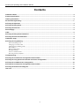
Contents
Installation Notes .......................................................................................................................................................... 2
Product Specification................................................................................................................................................... 2
Ordering Information.................................................................................................................................................... 2
20 Second Programming……………………………………………………………………………………………………….3
ACTentry A5 Operation ................................................................................................................................................ 4
ACTentry A5 Entry Panel ............................................................................................................................................. 5
ACTentry A5 Intercom.................................................................................................................................................. 5
Power Supply ................................................................................................................................................................ 6
Cable .............................................................................................................................................................................. 6
ACTentry A5 Entry Panel Installation ......................................................................................................................... 7
ACTentry A5 Intercom Installation.............................................................................................................................. 8
Installation steps .......................................................................................................................................................... 9
ACTentry A5 Programming........................................................................................................................................ 11
PIN Code Management..........................................................................................................................................................11 Changing User PIN Codes: ...................................................................................................................................................11 Changing Programming Code:..............................................................................................................................................11 Relay Timers ..........................................................................................................................................................................12 Relay Configuration...............................................................................................................................................................12 Backlight Settings ..................................................................................................................................................................13 Incorrect Code Lockout:........................................................................................................................................................13 Restoring Factory Defaults....................................................................................................................................................13 Troubleshooting.......................................................................................................................................................... 14
ACTentry A5 and Intercom Configuration with DC PSU......................................................................................... 15
ACTentry A5 entry panel with intercom and Phone Configuration ....................................................................... 15
ACTentry A5 and Switch Unit Configuration ........................................................................................................... 16
ACTentry A5 and Intercom Configuration with AC PSU......................................................................................... 17
ACTentry A5 Dimensioned Diagram ......................................................................................................................... 17
User List....................................................................................................................................................................... 18
1
ACTentry A5 Operating and Installation Manual
Rev 1.1
Installation Notes
• Remember to Factory Default the ACTentryA5 before programming
• Remember to place the supplied varistor across the terminals of the door strike coil to protect
the relay contacts
• Never use the on-board relays to switch AC mains voltage. An external relay, electrically
isolated from the ACTentryA5 should be used for this purpose
• Remember to change the programming code.
Product Specification
Number of Users
10
Entry Panel Supply Voltage
15 - 24V DC or AC
Intercom Supply Voltage
15 - 24V DC only
A5 Entry Panel Current Consumption
300mA (maximum)
Intercom Current Consumption
150mA (maximum)
Switch Unit Current Consumption
80mA (maximum)
Operating Temperature
-10 to +60 degrees C
Door Open Time
2 - 255 seconds
Max distance from Intercom and Entry Panel
200m maximum (Belden, CAT5 or
external rated CAT 5 for external use)
Relay Contact Rating
5A / 250Vac
Water Resistance
High IP56 (Entry Panel),
IP54 (Intercom)
Rugged Polycarbonate housing
Construction
Ordering Information
Product Code
Description
ACTENTRYA5E-PAN
entry panel (external)
ACTENTRYA5ICOM
intercom (internal)
ACTENTRYA5SWITCH
switch unit for multiple entry panels
ACTENTRYA5ICOM-K
intercom kit (entry panel, intercom & PSU)
ACTENTRYA5PSU
DC power supply unit
2
ACTentry A5 Operating and Installation Manual
Rev 1.1
20 Second Programming Guide
1.Factory Default:
Step
The ACTentry A5 may be returned to its
factory default settings at any time by
entering the programming mode and
pressing the tick ( ) key three times.
Keypad Entry
1
9999
Operation
Enter Programming Mode
2
Change Programming code
3
Exit programming
Note: The default Programming code is 9999 and the default code for User 1 is 1234. ACT
recommends these codes are changed immediately after defaulting.
2.Change Programming Code:
Example: Make 5214 the new
programming code
Step
1
9999
2
0
5214
3.Change User Code:
Example: Assign code 7529 to User 1
5214 0 1 7529
Operation
Enter Programming Mode
Change PIN codes
Change Programming code
3
4
9999 0
Keypad Entry
5214
5
Enter new 4-digit Programming code
Exit programming
Step
Keypad Entry
1
5214
Operation
Enter Programming Mode
2
0
Change PIN codes
3
1
Enter User Number 0-9
4
7529
4-digit code
5
Exit programming
4.Lost or forgotten programming code (Hardware factory Default)
If the Programming Code has been forgotten the unit maybe hardware factory defaulted. This will
set the programming code to 9999 and the code for user 1 to 1234.
1.
2.
3.
4.
5.
Remove the power from the ACTentry A5 Entry Panel.
Remove link LK1.
Apply power to unit (with LK1 removed).
Replace link LK1.
Programming Code is now set to 9999. Note: the unit has been factory defaulted.
Note: The ACTentry A5 will not operate correctly without LK1 in place. CALL led flashes amber rapidly.
3
ACTentry A5 Operating and Installation Manual
Rev 1.1
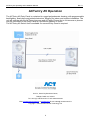
ACTentry A5 Operation
The ACTentry A5 Entry Panel is contained in rugged polycarbonate housing, with programmable
backlighting, dual relays and potted electronics, allowing for indoor and outdoor installation. The
unit will operate with the ACTentry Intercom and ACTentry Phone. Up to 4 intercoms or phones
may be connected to the Entry Panel at a maximum distance of 200m.
The ACTentry A5 Switch Unit is available if a second Entry Panel is required.
Unit C1, South City Business Centre,
Tallaght, Dublin 24, Ireland.
Tel: +353 (0)1 466 2570 UK Lo-call: 0845 300 5204
Web: www.accesscontrol.ie or www.act.eu E-mail: sales@ accesscontrol.ie
Copyright © 2009 Access Control Technology Ltd.
4
ACTentry A5 Operating and Installation Manual
Rev 1.1
ACTentry A5 Entry Panel
The Entry Panel is securely mounted on the wall at the entrance
to the premises. It consists of a speaker grille (label 2), CALL
button for visitors (label 3) and a keypad (label 4). The keypad is
used for PIN code access or to configure the unit.
Visitors press the CALL button to speak to the householder.
Regular users enter their PIN code to gain access (up to 10 User
Codes).
The keypad and call button are backlit for use in low ambient
light. The backlight can be switched off if desired.
The Entry Panel is rated for IP56. A security screw is concealed
under the cap (label 1).
The volume of the speaker may be adjusted if the unit is in a noisy environment (see page 7).
6 wires minimum are required to connect to the ACTentry Intercom or the ACTentry Phone.
Additional wires are required to connect the onboard relays to the gates or doors.
ACTentry A5 Intercom
The Intercom is mounted indoors and has an integrated speaker (label
2), TALK button (label 3), release buttons for Relay 1 and Relay 2 and
a volume control button (label 4).
Adjust Ring Volume
The Intercom rings when a visitor presses the CALL Button on the
Entry Panel. The volume of the ringing may be adjusted by pressing
the - and + keys.
Adjust Speech Volume
To answer the call, the householder presses the TALK button and begins speaking. The speech
volume may be adjusted using the - and + keys.
To end the call, the householder should press either 1 or 2 to activate the relays, or press the
TALK button.
Activate Relay Indefinitely (Toggle)
Each relay may be switched on indefinitely by holding down the corresponding key on the
intercom for five seconds. This allows the door or gate to be opened indefinitely and the
corresponding button will flash while the relay is active. Press the button again to restore the
relays to the normal state.
5
ACTentry A5 Operating and Installation Manual
Rev 1.1
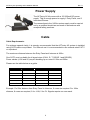
Power Supply
The ACTentry A5 kit comes with a 15V 800mA DC power
supply. This is enough power to supply 1 Entry Panel, and 3
Intercoms/Phones.
The connections to the 240Vac mains supply must be carried
out by a qualified electrician and made in accordance with
accepted safety practices.
Cable
Cable Requirements:
For optimum speech clarity, it is strongly recommended that the ACTentry A5 system is installed
using CAT5 cable or equivalent. For external use it is recommended to use external rated CAT 5
or equivalent.
The maximum distance between the Entry Panel and Intercom is 200m.
One CAT5 core is suitable for all signal wires (CALL, R, T, DOOR 1 and DOOR2).
Power cables (+VIN and 0V) require doubling up on runs of 100m and 200m.
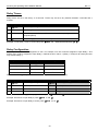
Please use the table below as a guide.
Connection
50m
100m
200m
+VIN
1
2
4
0V
1
2
4
CALL / I
1
1
1
R
1
1
1
T
1
1
1
DOOR1 / Z
1
1
1
Example: For 50m distance from Entry Panel to Intercom, 6 cores are required. For 100m
distance, 8 cores are required, 2 for +VIN, 2 for 0V. Signals require one core each.
6
ACTentry A5 Operating and Installation Manual
Rev 1.1
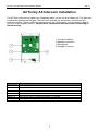
ACTentry A5 Entry Panel Installation
The ACTentry Entry Panel is made from 2 separate parts: a front unit and a base unit. The front
unit contains the speaker and keypad. The base unit contains the electronics, microphone and
connector blocks. The two units are interconnected via 2 flying leads, one for speaker (label 4)
and one for the keypad (label 6). Handle these connections with care when connecting or
disconnecting!
1.Connector Blocks
2.Volume potentiometer
3.Volt-Free Tamper
4.Speaker connector
5.Microphone
6.Keypad connector
7.Default Link LK1
Connector
Description
+VIN
0V
NO
C
NC
TAMP
CALL / I
R
O
T
DOOR1 / Z
DOOR 2
+DC Voltage of 15V to 24V or 24Vac
0 Volts
Normally Open Relay Contact
Common Relay Contact
Normally Closed Relay Contact
Normally Closed Dry Contact (Volt Free). Normally closed in tamper conditions.
Normally low output, + 15V signal to Intercom to ring when CALL button pressed
Audio signal intput from Intercom
0 Volts
Audio signal output to Intercom
Normally 5V input, 0V signal from Intercom and Phone to open Door 1
Normally 5V input, 0V signal from Intercom to open Door 2
7
ACTentry A5 Operating and Installation Manual
Rev 1.1
ACTentry A5 Intercom Installation
The ACTentry Intercom is made from 2 separate parts: a front unit and a base unit. The front unit
contains the speaker and keypad. The base unit contains the electronics, microphone and
connector blocks. The two units are interconnected via 2 flying leads, one for speaker (label 4)
and one for the keypad (label 6). Handle these connections with care when connecting or
disconnecting!
1.Connector Blocks
2.Speaker connector
3.Microphone
4.Keypad connector
Connector
Description
+VIN
0V
CALL / I
R
O
T
DOOR1 / Z
DOOR 2
+DC Voltage of 15V to 24V – Do not use AC.
0 Volts
Normally low input, + 15V signal to ring intercom
Audio signal output to Entry Panel
0 Volts
Audio signal input from Entry Panel
Normally 5V output, 0V signal when Button 1 is pressed
Normally 5V output, 0V signal when Button 2 pressed
8
ACTentry A5 Operating and Installation Manual
Rev 1.1
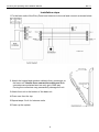
Installation steps
1.Fix the base units of the Entry Panel and Intercom to the wall and connect as shown below.
2. Attach the keypad and speaker cables to their connectors on
the base unit. Handle these connections with care! Both
connectors are polarised and can only go in ONE way.
Forcing the connectors may permanently damage the unit.
3.Attach front unit to the bottom of the base unit
4.Close over from the top.
5.Repeat steps 2 to 4 for Intercom units.
6.Power up the system.
9
ACTentry A5 Operating and Installation Manual
Rev 1.1
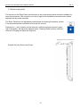
7.Test the audio quality.
The volume on the Entry Panel and Intercom is set in the factory which should be suitable for
most environments, if the volume is too low or high for the installed environment then further
adjusted can be made manually.
The Entry Panel has one adjustable potentiometer for altering the speech volume.
Turn the potentiometer clockwise to increase the volume.
Pressing the – and + buttons on the Intercom, while the speech channel is open
(call in progress), will adjust the speech levels. Pressing these buttons, while the
intercom is ringing will adjust the ring level.
8.Insert Security Screw and fit cap.
10
ACTentry A5 Operating and Installation Manual
Rev 1.1
ACTentry A5 Programming
On the Entry Panel, press the
button followed by the programming code (initially 9999). The
CALL led will flash amber while in programming mode. If
is pressed at any time or no key is
pressed within 30 seconds, programming mode is exited.
PIN Code Management
Changing User PIN Codes:
Step
Keypad Entry
1
xxxx
Operation
Example: Assign code 7529 to User 7
Enter Programming Mode
Enter Programming Mode
9999
2
0
Change PIN codes
0
Change PIN codes
3
0-9
Enter User Number 0-9
7
User 7
4
0000-9999
4 digit code
7529
PIN code
5
Exit programming
Exit programming
Example: To assign code 7529 to User 7 press:
9999 0 7 7529
Deleting User PIN Codes:
Step
Keypad Entry
1
xxxx
Operation
Example: Delete User 7 code
Enter Programming Mode
Enter Programming Mode
9999
2
0
Change PIN codes
0
Change PIN codes
3
0-9
Enter User Number 0-9
7
User 7
4
0000-9999
0000 deletes User code
0000
PIN code
5
Exit programming
Exit programming
Example: To delete User 7code press:
9999 0 7 0000
Changing Programming Code:
Step
Keypad Entry
1
2
xxxx
0
5
E.g. Set Programming code to 8282
Enter Programming Mode
9999
Change PIN codes
Enter Programming Mode
0
Change Programming code (Default 9999)
3
4
Operation
0000-9999
New 4 digit programming code
8282
New Programming Code
Exit programming
Exit programming
Example: To set Programming code to 8282 press:
11
9999 0
8282
ACTentry A5 Operating and Installation Manual
Rev 1.1
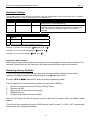
Relay Timers
Relay timers are set in the factory to 5 seconds. Timers may be set to any duration between 2 seconds and 4
minutes.
Step
Keypad Entry
1
Operation
Enter Programming Mode
xxxx
2
2
Set Relay Timers
3
0-1
0 For Relay 1, 1 for Relay 2. {Buzzer sounds indicating timing…wait
required period}
(Stop timing){Buzzer stops – timer set}
4
Example: To set Relay 1 time to 10 seconds press:
9999 2 0 ...wait 10 seconds, then
Relay Configuration
The Output Function code is assigned to a user. For example, one user could be assigned to open Relay 1 and
another user could be assigned to open Relay 2. Default function code is 1 (Relay 1 Timed) for all users (all users
only activate Relay 1).
Output Function Code
Relay 1
0
Toggled
1(Default)
Timed
Relay 2
2
Timed
3
Timed
Timed
When the door is toggled open, this will be indicated by the CALL indicator flashing.
Step
Keypad Entry
1
xxxx
Operation
Example: set User 7 to toggle the Relay open/locked
Enter Programming Mode
9999
Enter Programming Mode
2
1
Set Outputs
1
Set Outputs
3
0-9
Enter User Number 0-9
7
User 7
4
0-3
Enter ‘Output Function Code’
0
Toggled
Example: Set User 7 to toggle Relay 1 (open/locked) press:
Example: Set User 6 to open Relay 2 press:
9999 1 7 0
9999 1 6 2
Example: Set User 5 to open Relays 1 and 2 press:
9999 1 5 3
12
ACTentry A5 Operating and Installation Manual
Rev 1.1
Backlight Settings
The keypad backlight is permanently on by default. It may be programmed to come on only when a key is pressed
(Auto Backlighting), or it may be programmed to be completely off.
Option
Function
Default
Operation
Step
40
Permanent Backlight
On
41
Auto Backlighting
Off
Keypad Entry
When set, the keypad illumination is always on. This option will
override option 41 (Auto Backlighting).
When set, the keypad illumination is normally off, but will switch on
in response to any key being pressed or while in programming
mode. This option is overridden by option 40 (Permanent
Backlight).
Operation
1
xxxx
2
40 or 41
2 digit option number
3
0 or 1
0 = Off, 1 = On
Enter Programming Mode
To prevent any illumination, turn off options 40 and 41.
9999 40 0 41 0
Example: To prevent any illumination:
Example: To turn off Permanent Backlight:
Example: To turn on AutoBacklight:
9999 40 0
9999 41 1
Incorrect Code Lockout:
When three invalid codes have been entered in a row, the keypad will enter lockout mode for 20
seconds. During this time, the Call button will flash red and all user codes will be inactive.
Restoring Factory Defaults
The ACTentry A5 entry panel may be returned to its factory default settings at any time by
entering the programming mode and pressing the tick ( ) key three times.
Example:
5214
(where 5214 was set as the programming code)
If the Programming Code has been forgotten, it may be set to 9999 by:
1.
2.
3.
4.
5.
Remove the power from the ACTentry A5 Entry Panel.
Remove link LK1.
Apply power to unit (with LK1 removed).
Replace link LK1.
Programming Code is now set to 9999.
Note: The ACTentry A5 will not operate correctly without LK1 in place. CALL led flashes amber
rapidly.
This will set the programming code to 9999 and the code for user 1 to 1234. ACT recommends
these codes are changed immediately.
13
ACTentry A5 Operating and Installation Manual
Rev 1.1
Troubleshooting
Low Speech Volume at the Entry Panel
1. Volume adjustment required on the Entry Panel.
2. Entry Panel grill is blocked
3. Entry Panel or Intercom/Phone supply voltage is low (Minimum of 15V DC required)
No speech when the Intercom/Phone is buzzed
1. Wiring fault on the speech signal connections R or T. R carries the audio from the
Intercom/Phone to the Entry Panel. T carries audio from the Entry Panel to the
Intercom/Phone.
Intercom/Phone will not buzz
1. Faulty 0V or CALL line between power supply and phone. Check for a voltage level
between 13V and 15V, between CALL and 0V, when CALL button pressed.
Intercom/Phone Release button does not operate relay
1. Fault on DOOR1 / I or 0V line. Check that it goes to 0V when Button 1 on the intercom
is pressed.
14
ACTentry A5 Operating and Installation Manual
Rev 1.1
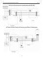
ACTentry A5 and Intercom Configuration with DC PSU
ACTentry A5 Entry Panel with Intercom and Phone Configuration
15
ACTentry A5 Operating and Installation Manual
Rev 1.1
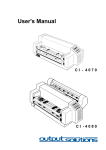
ACTentry A5 and Switch Unit Configuration
16
ACTentry A5 Operating and Installation Manual
Rev 1.1
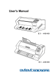
ACTentry A5 and Intercom Configuration with AC PSU
ACTentry A5 Dimensioned Diagram
Measurements in mm
17
ACTentry A5 Operating and Installation Manual
Rev 1.1
User List
User
User Name
PIN
Toggle
0
1
2
3
4
5
6
7
8
9
Example:
5
7529
John Smith
18
No