1
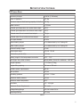
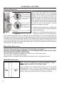
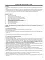
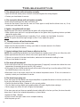
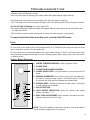
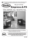
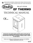
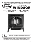
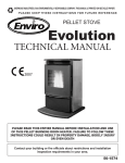
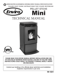
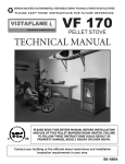
SHERWOOD INDUSTRIES IS AN ENVIRONMENTALLY RESPONSIBLE COMPANY. THIS MANUAL IS PRINTED ON RECYCLED PAPER. PLEASE KEEP THESE INSTRUCTIONS FOR FUTURE REFERENCE PELLET STOVE EF THERMO 28 TECHNICAL MANUAL ���� PLEASE READ THIS ENTIRE MANUAL BEFORE INSTALLATION AND USE OF THIS PELLET-BURNING ROOM HEATER. FAILURE TO FOLLOW THESE INSTRUCTIONS COULD RESULT IN PROPERTY DAMAGE, BODILY INJURY OR EVEN DEATH. Contact your building or fire officials about restrictions and installation inspection requirements in your area. 50-878 Table of Contents Introduction........................................................................................3 Rating Label Location................................................................3 Important Safety Data...............................................................3 Safety Warnings And Recommendations.....................................3 Specifications......................................................................................5 EF Thermo Data.......................................................................5 Appliance Dimensions...............................................................6 Safety Devices..........................................................................7 Installation..........................................................................................9 Deciding Where to Locate your Pellet Appliance..........................9 Removing Your New Stove From the Pallet..................................9 Slider/Damper Operation...........................................................9 Installation of Expansion Tank..................................................10 Vent Termination Requirements................................................10 Clearances to Combustibles.....................................................12 Alcove Clearances...................................................................12 Water Line Schematic..............................................................13 Horizontal Through Wall Installation.........................................14 Through Wall Installation.........................................................15 Inside Vertical Installation........................................................16 Outside Vertical Installation.....................................................17 Thermostat Installed...............................................................18 Mobile Home Installation.........................................................18 Fresh-Air Connections.............................................................18 Troubleshooting.................................................................................19 Fuses.....................................................................................21 Control Board Functions..........................................................21 Wiring Diagram.................................................................................22 Parts List...........................................................................................23 Parts Diagram - Components..............................................................24 Parts Diagram - Body.........................................................................25 Warranty...........................................................................................26 Installation Data Sheet.......................................................................27 This manual is to be used by technicians for installation and service instructions. 2 Introduction RATING LABEL LOCATION: The rating label is located on the hopper lid. IMPORTANT SAFETY DATA: Please read this entire Owner’s Manual before installing or operating this ENVIRO Pellet Stove. Failure to follow these instructions may result in property damage, bodily injury or even death. Contact your local building or fire official to obtain a permit and any information on installation restrictions and inspection requirements for your area. To prevent the possibility of a fire, ensure that the appliance is properly installed by adhering to the installation instructions. An ENVIRO dealer will be happy to assist you in obtaining information with regards to your local building codes and installation restrictions. Be sure to maintain the structural integrity of the home when passing a vent through walls, ceilings, or roofs. The stove’s exhaust system works with negative combustion chamber pressure and a slightly positive chimney pressure. It is very important to ensure that the exhaust system be sealed and airtight. The ash pan and viewing door must be locked securely for proper and safe operation of the pellet stove. Do not burn with insufficient combustion air. A periodic check is recommended to ensure proper combustion air is admitted to the combustion chamber. Setting the proper combustion air is achieved by adjusting the slider damper located on the left side of the stove. When installing the stove in a mobile home, it must be electrically grounded to the steel chassis of the home and bolted to the floor. Make sure that the structural integrity of the home is maintained and all construction meets local building codes. Soot or creosote may accumulate when the stove is operated under incorrect conditions such as an extremely rich burn (black tipped, lazy orange flames). If the creosote is ignited it will make an extremely hot fire, therefore, the smoke pipe and chimney should be inspected regularly to determine if a build-up has occurred. If creosote has accumulated it should be removed to reduce the risk of a chimney fire. If a fire occurs throw a cup of water into the firebox, close the door, and call the fire department. If you have any questions with regard to your stove or the above-mentioned information, please feel free to contact your local dealer for further clarification and comments. IMPORTANT: The heated water from this unit is not for human consumption, but for heating potable water through heat exchange only. WARNING: No modifications can be preformed to this appliance prior authorization from the manufacturer. Use only Enviro approved replacement parts SAFETY WARNINGS AND RECOMMENDATIONS: Caution: Do not connect to any air distribution duct or system. Do not burn garbage or flammable fluids such as gasoline, naptha or engine oil. Unit hot while in operation. Keep children, clothing and furniture away. Contact may cause skin burns. 3 Introduction SOOT: Operation of the stove with insufficient combustion air will result in the formation of soot which will collect on the glass, the heat exchanger, the exhaust vent system, and may stain the outside of the house. This is a dangerous situation and is inefficient. Frequently check your stove and adjust the slider/ damper as needed to ensure proper combustion. Electrical: THE USE OF A SURGE PROTECTED POWER BAR IS RECOMMENDED. The maximum power requirement is 800 watts (3.3 amp). The stove has a grounded electrical cord and should be connected to a standard 220-240 volt, 50 Hz grounded electrical outlet. Make sure the electrical cord is not trapped under the appliance and that it is clear of any hot surfaces or sharp edges. When installing the stove in a mobile home, it must be electrically grounded to the steel chassis of the home and bolted to the floor in accordance with applicable local, state or federal codes. GLASS: Do not abuse the glass by striking or slamming the door. Do not attempt to operate the stove with broken glass. The stove uses ceramic glass. Replacement glass must be purchased from an ENVIRO dealer. Do not attempt to open the door and clean the glass while the unit is in operation or if glass is hot. To clean the glass, use a soft cotton cloth and mild window cleaner, gas or wood stove glass cleaner, or take a damp paper towel and dip into the fly ash. This is a very mild abrasive and will not damage the glass. FLAMMABLE LIQUIDS: Never use gasoline, gasoline-type lantern fuel, kerosene, charcoal lighter fluid, or similar liquids to start or “freshen up” a fire in the heater. Keep all such liquids well away from the heater while it is in use. SMOKE DETECTOR: Smoke detectors should be installed and maintained in the structure when installing and operating a pellet burning appliance. OPERATION: The ash pan and door must be closed securely for proper and safe operation of the pellet stove. Also ensure all gaskets on the door are checked and replaced when necessary. INSTALLATION: Be sure to maintain the structural integrity of your home when passing a vent through walls, ceilings, or roofs. It is recommended that the unit be secured into its position in order to avoid any displacement. DO NOT INSTALL A FLUE DAMPER IN THE EXHAUST VENTING SYSTEM OF THIS UNIT. DO NOT CONNECT THIS UNIT TO A CHIMNEY FLUE SERVING ANOTHER APPLIANCE. FRESH AIR: Outside Fresh Air connection is optional. Must be connected to all units installed in Mobile and “Air Tight Homes” (R2000) or where required by local codes. Consider all large air moving devices when installing your unit and provide room air accordingly. Limited air for combustion may result in poor performance, smoking and other side effects of poor combustion. If you have any questions with regards to your stove or the above-mentioned information, please feel free to contact your local dealer for further clarification and comments. SINCE SHERWOOD INDUSTRIES LTD. HAS NO CONTROL OVER THE INSTALLATION OF YOUR STOVE, SHERWOOD INDUSTRIES LTD. GRANTS NO WARRANTY IMPLIED OR STATED FOR THE INSTALLATION OR MAINTENANCE OF YOUR STOVE. THEREFORE, SHERWOOD INDUSTRIES LTD. ASSUMES NO RESPONSIBILITY FOR ANY CONSEQUENTIAL DAMAGE(S). SAVE THIS INSTRUCTION MANUAL FOR FUTURE REFERENCE 4 Specifications EF THERMO DATA: Necessary draught 34.8 Pa (0.348 mbar) Mass of Appliance 157 Kg Minimum required load bearing capacity of the floor 247 Kg Water content 17.3 liters Exhaust gas temperature at nominal heat output 230°C Exhaust gas temperature at minimum heat output 120°C Exhaust mass flow at nominal heat output 7.5 g/s Exhaust mass flow at minimum heat output 8.0 g/s Flue pipe diameter 80 mm Space heating output to be determined by Lab Testing KW Water heating output to be determined by Lab Testing KW Nominal heating output 25 kW Heat output range 2.5 kW - 25 kW Combustion period at QN 12 hours Setting range for the temperature controller 30°C - 75°C Fuel (type, size, water content) Wood pellets, 6 mm dia. maximum, <8% W.C. Hopper capacity 77.75 liters (55 Kg) Hopper filing opening 440 mm x 320 mm Auxiliary power requirements 800 W Test pressure 4.5 bar Operating pressure 0.5 bar - 2.5 bar Maximum water pressure 3.0 bar Maximum water temperature 90°C Burn Rate 1.0 - 4.5 Kg/hr Maximum Power Requirement 800 watts Voltage Rating Range 220-240 volt at 50 Hz Amperage Rating 3.3 Amp Table 1 5 Specifications APPLIANCE DIMENSIONS: UNIT DIMENSIONS HEIGHT: 37 3⁄8” (949 mm) WIDTH: 25 1⁄4” (641 mm) DEPTH: 25 7/16” (646 mm) 37 3/8" (94.9cm) HEARTH PAD: WIDTH: 25 1⁄4” (641 mm) DEPTH: 31 3/16” (793 mm) [6” (152.4 mm) in front of unit] 25 7/16" (64.6cm) 25 1/4" (64.1cm) Figure 1 ���� ���� ����� ��� ����� ������ ����� ���� �� ����� ������ ����� ��� ������ ������� �� ������ ������ �� ���� ������ ���� ���� �� ���� ������ � ���� ������ � ���� ������ � ������ ������ � ���� ����� � ���� ������ Figure 2 6 � ���� ������ Specifications SAFETY DEVICES: Air Bleeder Valve (shown in Figure 3): Located under unit top of the unit. To remove the top follow these steps (refer to Figure 4): 1. Open hopper lid and remove the two (2) screws at the front. 2. Loosen the two (2) screws at the back of the top. 3. Remove top. 4. Replace the top by using the reverse of the method used to remove it. ��� ������� ����� Refer to Figure 5 and 6 for the following safety devices. See next page to remove cabinet sides. Figure 3 WARNING: DO NOT TAMPER, REMOVE, OR BYPASS THE FOLLOWING SAFETY DEVICES. DOING SO COULD RESULT IN PROPERTY DAMAGE, BODILY INJURY OR EVEN DEATH. Low Pressure Switch: Located behind right cabinet side. Water Temperature Limit Switch: Located behind right cabinet side. Pressure Relief Valve: Located behind left cabinet side. Figure 4 ��� �������� ������ ����� ����������� ����� ������ �������� ������ ����� ����� ���������� Figure 5 Figure 6 7 Specifications To remove the cabinet sides, follow these steps: 1. Loosen the three (3) screws from both sides on the back of the appliance (see Figure 7). 2. Remove the ash drawer cover (see Figure 8). 3. Remove the four (4) screws, two on each side, under the ash drawer holding the cabinet sides on (see Figure 9). 4. Slide cabinet side forward and out. 5. Replace cabinet sides by using the reverse of the method used to remove them. 6. Replace the ash pan cover. Ash drawer Ash drawer cover Figure 7 Figure 8 Figure 9 8 Installation All local regulations, including those referring to national and European Standards need to be complied with when installing this appliance. DECIDING WHERE TO LOCATE YOUR PELLET APPLIANCE: 1. Check clearances to combustibles to the unit and for the venting as per the pellet vent manufacturer’s installation instructions. 2. Do not obtain combustion air from an attic, garage or any unventilated space. Combustion air may be obtained from a ventilated crawlspace. 3. Do not install the stove in a bedroom. 4. You can vent the stove through an exterior wall behind the unit or connect it to an existing masonry or metal chimney (must be lined if the chimney is over 6” in diameter, or over 28 inches² cross sectional area). An interior vent can be used with approved pipe passing through the ceiling and roof. 5. Locate the stove in a large and open room that is centrally located in the house. This will optimize heat circulation. 6. The power cord is 8 feet (2.43 m) long and may require a grounded extension cord to reach the nearest electrical outlet. REMOVING YOUR NEW STOVE FROM THE PALLET: To remove your new stove from its pallet you must remove both cabinet sides. This is done by the following steps (refer to Figures 7, 8, and 9 in the section Specifications - Safety Devices): 1. Loosen the three (3) screws from both sides on the back of the appliance. 2. Remove the ash pan cover. 3. Remove the four (4) screws, two (2) on each side, next to the ash pan holding the cabinet sides on. 4. Slide cabinet sides forward and out. 5. Remove the two (2) screws, one on each side, that are holding the base of the unit to the pallet. 6. Remove the unit from the pallet. 7. Replace cabinet sides using the reverse of the method used to remove them. 8. Replace the ash pan cover. SLIDER/DAMPER OPERATION: This is used to regulate the airflow through the pellet stove. • On the low heat output settings, push the slider all the way in. ���� ��� • On the high heat output pull the slider out or until a good fire is achieved. A good fire is in between a fire with lazy black tipped flames and a forced fire (very quick, shorter flames). A good fire is the most efficient and will have a bright and active flame. ���� ��� • Slider should be set at a hot magnehelic reading of 0.14” W.C. (34 Pa) for firebox vacuum. Figure 10 9 Installation INSTALLATION OF EXPANSION TANK: The expansion tank MUST be installed before this unit can be used. 1. Remove the expansion tank from the box located in the hopper. 2. Loosen the four (4) screws pointed out in Figure 11. Lift the back grill up and remove it from the unit. 3. Apply thread sealant to the fitting point out in Figure 12 then tighten the expansion tank onto the fitting. Figure 11 Figure 12 VENT TERMINATION REQUIREMENTS: It is recommended that your pellet stove be installed by an authorized dealer/installer. Use Table 2 in conjunction with Figure 13 for allowable exterior vent termination locations. Table 2 Minimum Clearance 10 A 24 in (61 cm) B 48 in (122 cm) Description Above grass, top of plants, wood, or any other combustible materials. From beside/below any door or window that may be opened. C 24 in (61 cm) From above any door or window that may be opened. D 24 in (61 cm) To any adjacent building, fences and protruding parts of the structure. E 24 in (61 cm) Below any eave or roof overhang F 12 in (30 cm) To outside corner. G 12 in (30 cm) To inside corner, combustible wall (vertical and horizontal terminations). H 3 ft (91 cm) within a height of 15 ft (4.5 m) above the meter/regulator assembly To each side of center line extended above natural gas or propane meter/ regulator assembly or mechanical vent. I 3 ft (91 cm) J 12 in (30 cm) From any forced air intake of other appliance Clearance to non-mechanical air supply inlet to building, or the combustion air inlet to any appliance. K 24 in (61 cm) Clearance above roof line for vertical terminations. L 7 ft (2.13 m) Clearance above paved sidewalk or paved driveway located on public property. Installation G K E D F B Opens G Opens B A Termination Cap Air Supply Inlet G C I Opens G Gas Meter Restriction Zone L H (Termination not allowed) Figure 13 1. Do not terminate the vent in any enclosed or semi-enclosed areas such as a carport, garage, attic, crawlspace, narrow walkway, closely fenced area, under a sundeck or porch, or any location that can build up a concentration of fumes such as stairwells, covered breezeway, etc. 2. Vent surfaces can become hot enough to cause burns if touched by children. Non-combustible shielding or guards may be required. 3. Termination must exhaust above the inlet elevation. It is recommended that at least five feet of vertical pipe be installed outside when the appliance is vented directly through a wall, to create some natural draft to prevent the possibility of smoke or odor during appliance shut down or power failure. This will keep exhaust from causing a nuisance or hazard from exposing people or shrubs to high temperatures. In any case, the safest and preferred venting method is to extend the vent through the roof vertically. 4. Distance the from bottom of the termination and grade is 12” (30 cm) minimum. This is conditional upon the plants and nature of grade surface. The exhaust gases are hot enough to ignite grass, plants and shrubs located in the vicinity of termination. The grade surface must not be lawn. 5. If the unit is incorrectly vented or the air to fuel mixture is out of balance, a slight discoloration of the exterior of the house might occur. Since these factors are beyond the control of Sherwood Industries Ltd, we grant no guarantee against such incidents. NOTE: Venting terminals shall not be recessed into walls or siding. 11 Installation CLEARANCES TO COMBUSTIBLES: C B A Floor Protection Figure 14 This unit can be installed on a combustible floor due to the built in pedestal hearth pad (for example linoleum, hardwood flooring). If combustible flooring is underneath the unit 6 inches (153 mm) on either side and to the front must be protected by non-combustible material. If this unit is to be installed onto a carpeted surface, a hearth pad must be used for stability. NOTE: These dimensions are minimum clearances but it is recommended that you ensure sufficient room (20” [508 mm]) on either side) for servicing, routine cleaning and maintenance. Do not block any of the air intake grills. Maintain these clearances to combustibles. A) Side wall to unit B) Back wall to unit C) Adjacent wall to corner of unit - Mantle (Hearth Mount) 6 1 1 8 inches inch inch inches (153 mm) ( 25 mm) ( 25 mm) (203 mm) ALCOVE CLEARANCES: This unit may be installed in an alcove. Maintain clearances to combustibles. 36" (90cm) ) cm 75 ( " 30 Minimum Alcove width Minimum alcove height Maximum alcove depth 36 inches ( 914 mm) 48 inches (1220 mm) 30 inches ( 762 mm) 48" (120cm) Install vent at clearances specified by the vent manufacturer. Figure 15 12 Installation WATER LINE SCHEMATIC: EF Thermo 28 Expansion Tank Heater Pump Valve Pressure Relief Valve Hot Cold Supply Shut-Off Valve Hot Water Tank Check Valve Pressure Regulator Radiator Radiator Supply The heating system for this unit must be engineered to accommodate the output of the unit. All pipes must be installed by a licensed plumber. Figure 16 13 Installation HORIZONTAL THROUGH WALL INSTALLATION: The ENVIRO EF THERMO can be vented by a couple of different methods. 1. NOTE: Use only listed type “PL” or “L” pellet venting products. Failure to use listed components may cause damage or personal injury or death. 2. Choose a location for your stove that meets the requirements stated in this manual and allows installation with the least amount of interference to house framing, plumbing, wiring, etc. 3. Install a non-combustible hearth pad underneath the unit extending 6 inches (15 cm) in front of and to the sides. 4. Place the stove 15” (38.1 cm) away from the wall. If the stove is to be set on a hearth pad, set the unit on it. 5. Locate the center of the exhaust pipe on the stove. Extend that line to the wall. Once you have located the center point on the wall, refer to pellet vent manufacturer installation instructions for the correct hole size and clearances to combustibles. 6. Install the wall thimble as per the instructions written on the thimble. Maintain an effective vapor barrier. 7. Install a 2’ or 3’ (61 or 92 cm) length of 3” (7.6 cm) or 4” (10.2 cm) listed type “PL” or “L” vent pipe into the wall thimble. The pipe should install easily into the thimble. 8. Install the fresh air intake (see the section entitled FRESH AIR CONNECTIONS). 9. Connect the exhaust vent pipe to the exhaust pipe on the stove. 10. All Joints in the vent system shall be fastened with (3) three screws. Seal the connection with high temperature silicone. 11. Push the stove straight back, leaving a minimum of 1” (2.5 cm) clearance from the back of the stove to the wall. Seal the vent pipe to the thimble with high temperature silicone. 12. The pipe must extend at least 12’ (30.5 cm) away from the building. If necessary, bring another length of pipe (PL type) to the outside of the home to connect to the first section. Do not forget to place high temperature silicone around the pipe that passes through the thimble. 13. Install a vertical pipe; or, if all requirements for direct venting are met, install vent termination. The stainless steel cap termination manufactured by the vent manufacturer is recommended. However, when the vent terminates several feet above ground level and there are no trees, plants, etc. within several feet, a 45 degree elbow can be used as termination. The elbow must be turned down to prevent rain from entering. NOTE: Some horizontal, through the wall installations may require a “T” and 4-5 feet (1.2-1.5 m) of vertical pipe outside the building to help draft the stove. This may be required if a proper burn cannot be maintained after the stove has been tested and the airflow set. This is due to back-pressure in the exhaust, caused by the air flow around the house 14 Installation THROUGH WALL INSTALLATION: Fresh-Air Intake 1” (25mm) Wall thimble manufactured by pellet vent manufacturer. 1” (25mm) 6” (150mm) Floor Protection Figure 17 1” (2.5cm) Wall Thimble 45° Elbow 6” (15.2cm) Non-combustible Floor Protection 12” (30.5cm) Fresh-Air Intake Existing Floor (combustible) Rodent Mesh Cap Figure 18 15 Installation INSIDE VERTICAL INSTALLATION: 1. Choose a stove location that is ideal. See the section Deciding Where to Locate Your Pellet Appliance. 2. Place a non-combustible hearth pad where necessary. 3. Place the unit on the hearth pad and space it in a manner so when the pellet vent is installed vertically, it will be 3” (76 mm) away from a combustible wall. 4. Locate the center of the fresh air intake pipe on the unit. Match that center with the same point on the wall and cut a hole about 1 5/8” (41 mm) in diameter. 5. Install the fresh-air intake pipe. Rain cap 6. Install the tee with clean out. Flashing 7. 36” (91cm) 3” (7.5cm) clearance 8. Finally, extend the pellet vent to go through the roof flashing. Use wall thimble or ceiling firestop 3” Tee with cleanout 6” (15cm) Non-combustible floor protection 6” Fresh-air intake Existing floor (combustible) Figure 19 16 Install the pellet vent upward from there. When you reach the ceiling make sure that the vent goes through the ceiling firestop. Maintain a 3” (76 mm) distance to combustibles and keep attic insulation away from the pipe. 9. Ensure that the rain cap is approximately 36” (914 mm) above the roof. Installation OUTSIDE VERTICAL INSTALLATION: To accomplish an outside vertical installation, follow steps 1 through 9 in the Inside Vertical Installation section and then finish it by performing the following: 10. Install a tee with clean out on the outside of the house. 11. Install PL vent upward from the tee. Make sure that you install support brackets to keep the vent straight and secure. 12. Secure the flashing as you go through the roof. 13. Ensure that the rain cap is approximately 36” (914 mm) above the roof. Rain Cap Flashing 36” (91cm) 2” (5cm) 3” (7.5cm) clearance Support bracket Tee with cleanout 6” (15cm) Type “L” Vent Fresh-air intake Non-combustible floor protection Existing floor (combustible) Figure 20 17 Installation THERMOSTAT INSTALLED: A) HI / LOW: When the jumper is placed on only one of the J9 pins, then the control board is in a HI / LOW mode of thermostat operation (factory setting). B) ON / OFF: If both pins of J9 are jumped (covered), the control board is in an ON / OFF mode of thermostat operation . Remove jumper wire and install thermostat wires here Figure 21 This control board can be placed into two different modes: When the jumper J9 is not jumped then the control board is in a HI / LOW mode operation. If the control board is placed with J9 jumped then the control board is in a ON / OFF mode of operation. In the ON /OFF thermostat mode, the unit will shut OFF when the thermostat is not calling for heat. When the thermostat calls for heat, the unit will go through an ignition sequence once again and relight. 1. Install the wall thermostat in a location that is not to close too the unit but will effectively heat the desired area. 2. Install a 12 or 24 Volt Thermostat using an 18 x 2 gauge wire from the unit to the thermostat. If the unit has been placed in the HI / LOW mode, the unit will be taken to a low or idle setting when the thermostat is not calling for heat. When the thermostat calls for heat, the unit will go to the setting that is displayed on the control board Heat Indicator. If the heating load is not great enough when the stove is on low, the high limit switch will turn the stove off and the switch will have to be manually reset. To reset the high limit switch, remove the right cabinet side. The switch is found behind the control panel. Avoid setting off the high limit switch. MOBILE HOME INSTALLATION: •Secure the heater to the floor using the two bolt holes supplied in the pedestal. CAUTION: THE STRUCTURAL INTEGRITY OF THE MANUFACTURED HOME FLOOR, WALL, AND CEILING/ROOF MUST BE MAINTAINED. •Ensure the unit is electrically grounded to the chassis of your home (permanently). •Do not install in a room where people sleep. •Outside fresh air is mandatory when installing into airtight homes or manufactured homes. FRESH-AIR CONNECTIONS: NOTE: Fresh air is mandatory on all units installed in “Mobile Homes” as well as in “Air Tight” homes. 5 cm Diameter Optional Elbow Figure 22 18 When connecting to an outside fresh-air source, do not use plastic, combustible pipe. Only 2” (5 cm) ID steel, aluminum or copper pipe should be used. It is recommended, when you are installing a fresh-air system, to keep the number of bends in the pipe to a minimum. Troubleshooting DO NOT: • Hold the ON / OFF BUTTON; this is a momentary contact switch and can be damaged if held down too long. • Service the stove with wet hands. The stove is an electrical appliance, which may pose a shock hazard if handled improperly. Only qualified technicians should deal with possible internal electrical failures. • Do not remove any screws in the firebox without first lubricating them with penetrating oil. WHAT TO DO IF: 1. 2. 3. 4. 5. 6. 7. 8. 9. 10. The stove will not start. The stove will not operate when hot. The exhaust blower will not function normally. The convection blower will not function normally. Ignitor : The pellets will not light. The auger motor does not function normally. Control settings (heat level) have no effect on fire. The stove will not shut off. The stove keeps going out. The #2 light is flashing. *NOTE: All troubleshooting procedures should be carried out by qualified technicians or installers. 1. The stove will not start. üMake sure the stove is plugged in and the wall outlet is supplying power. üPush the ON /OFF button. üIf the Control Board has been placed in the ON /OFF thermostat mode, then turn the thermostat up to call for heat. üIf the unit still does not start, contact your local service dealer for service. 2. The stove will not operate when hot. «Check the hopper for fuel. «Incorrect air damper setting - Excessive air may consume the fire too quickly before the next drop of fuel, leaving completely unburned fuel in the burn pot liner. Insufficient air will cause build up, further restricting the air flow through the Burn Pot Liner. This, in turn, will cause the fuel to burn cold and very slowly. Fuel may build up and smother the fire. (NOTE: Unit may require a change to the vent system or installation of fresh air to correct Air to Fuel ratio problems). «Combustion Blower failure - The Combustion Blower is not turning fast enough to generate the proper vacuum in the fire box. Visual Check – is the blower motor turning? «Check Vacuum levels in the firebox with a Magnahelic gauge and an 1⁄8” tube placed through the small hole under the ash sill (readings must be above .13” W.C. on low fire). Note: If the motor fails to reach a 0.13” W.C. reading, then replace the Combustion Blower. «Poor Quality Fuel – Insufficient energy in the fuel to produce enough heat to keep the stove burning or operational. «Exhaust Temperature Sensor failure – Bypass sensor located on Exhaust Channel. If stove now operates properly, the unit may require cleaning or a new sensor. Contact your local dealer for service. «The unit may require cleaning. Contact your local dealer for service. «The third red LED light in the heat level indicator light will flash if a fire is not detected or if the fire has gone out. 19 Troubleshooting 3. The exhaust motor will not function normally. üOpen the left side access panel; check all connections against the wiring diagram. üContact your local dealer for service. 4. The convection blower will not function normally. «Clean all grill openings at the back and below unit. «Press the fan button. Does the fan come on? Press again to verify that the blower turns on; if not, contact your local dealer for service. 5. Ignitor- the pellets will not light. Everything else in the stove operates but the ignitor will not light the pellets üMake sure the burn pot liner is up tight and square to the ignitor tube (by pushing the burn pot back against the ignitor tube). üCheck to see if the exhaust blower is operating. If not, contact your local dealer for service. NOTE: The ignitor should be bright orange in color. If not, replace the ignitor. 6. The auger motor will not function normally. «Check for obstructions in the hopper system. «Make sure the vacuum switch is closing; open slider to increase vacuum in the firebox. «Call your local dealer for service. 7. Control settings (Heat Level) have no effect on the fire. NOTE: If the system light is flashing, the Control Board has complete control of the unit. When the unit’s system light becomes solid, then control of the unit is given back to the operator. üIf there is no control of the Heat Level button, make sure the thermostat is calling for heat. üCall your local dealer for service. 8. The stove will not shut off. «If the unit will not shut off, ensure that the thermostat (if equipped) is turned down below the room temperature (thermostat mode in the ON / OFF position). «If the unit is in the HI/LOW mode the unit will not shut off but will go to an idle setting (LOW). Press the ON/OFF button to turn the unit off. «Disconnect one of the brown wires from the exhaust temperature sensor. If the unit continues to operate, contact your local dealer for service. 9. The stove keeps going out. If the stove goes out and leaves fresh unburned pellets or cigarette-like ashes in the burn pot liner, the fire is going out before the stove shuts off. üCheck to see that the Slider / Damper is in the correct position. üTurn the Heat Level up slightly (poor quality pellets will require slightly higher settings). üSet the auger trim till the #1 and #5 lights are illuminated. If the stove goes out and there are partially burned pellets left in the burn pot liner, the stove has shut down due to a lack of air, exhaust temperature, or power failure. «Adjust the Slider / Damper. «Check to see if the stove needs a more complete cleaning. «Did the power go out? 20 Troubleshooting «Contact your local Dealer for service. «Turn the Heat Level up slightly (poor quality pellets will require slightly higher settings). If the stove goes out and there are no pellets in the liner, the auger is stopping. üSee “The auger motor will not function normally” and “The exhaust blower will not function normally.” 10. The #2 light is flashing. (see #8 in Figure 23) «The water temperature high limit switch has tripped. Remove right cabinet side and manually reset the high limit switch. «The low water pressure switch has tripped. Increase the water pressure in the system. To reset Circuit Board after a trouble code - push the ON/OFF button FUSES: F1 is the fuse to the inside of the circuit board controls. If F1 has blown there may have been an input power overload or a short in the convection fan. F2 fuse closest fuse to the outside edge of the circuit board controls. If fuse F2 has blown then there was a electrical overload problem with one of the following parts: ignitor, auger motor, high limit switch, or exhaust blower. CONTROL BOARD FUNCTIONS: 1. WATER TEMPERATURE DIAL: Read in degrees Celsius 2. AUGER TRIM 3. CONVECTION BLOWER CONTROL � 4. AUGER PULSE LIGHT: This light flashes in conjunction with the auger. 5. MANUAL AUGER FEED: If the unit runs out of fuel, this button can be used to “prime the auger system”. This button will turn off after 60 seconds and then must be released and pressed again. � � � � � � � � 6. SYSTEM LIGHT: If flashing, the board is under control. If the light is solid, setting can be altered. 7. ON/OFF BUTTON 8. HEAT OUTPUT INDICATOR: Shows the present heat output setting. Has lights 1 - 5. 9. HEAT LEVEL ADJUSTMENT: When pressed, will change the heat setting of the unit from low to high. Figure 23 NOTE: This unit is capable of continuous operation if the heat demand is high enough to require the unit to stay on. 21 Wiring Diagram 200 °F 93 °C HIGH LIMIT WATER TEMPERATURE SENSOR LOWER PRESSURE SENSOR GREY GREY GREY GREY BLUE COMBUSTION BLOWER WHITE BROWN POWER CORD 120°F 49°C EXHAUST TEMPERATURE SENSOR BROWN BLACK RED BLACK WHITE GROUND J2 LIGHT BLUE IGNITOR COMMON BLACK BROWN HOT 5 A FUSES BLACK THERMOSTAT 5 VDC 120°F 49°C SENSOR RED PURPLE Pump WHITE WHITE CONVECTION BLOWER PURPLE WHITE AUGER MOTOR VACUUM SWITCH BLACK YELLOW WHITE WHITE ORANGE ORANGE PURPLE BLUE YELLOW RED GREY GREY BROWN BROWN RED ORANGE ORANGE RED WATER THERMOSTAT 22 CONNECT OPTIONAL WALL THERMOSTAT HERE Parts List Reference Number Part Description Part Number 1 120°F (49°C) exhaust temperature sensor EC-001 2 Vacuum switch - 220V 3 Auger Brass Bushings (Set Of 2) 4 Hardened Bushing 20-020 5 Tube cleaner rod 50-680 6 300 Watt Ignitor - 220V 50-829 DIN Owner’s Manual 50-877 DIN Technical Manual 50-878 7 Circuit board - 220V 50-1015 8 Auger Motor-3RPM-220V 50-1024 9 Convection Blower - 220V 50-1025 10 Water Pump 50-1026 EF-017-220V EF4i-065 11 Low Pressure Switch 50-1027 12 Water Thermostat 50-1028 13 Water High Limit (Manual Reset) 50-1029 14 Expansion Tank 50-1030 15 Shut Off Air Bleeder 50-1031 16 Pressure Relief Valve 50-1032 17 Hopper Lid 50-1042 18 Top 50-1043 19 Cab Side Right 50-1044 20 Cab Side Left 50-1045 21 Louver Set Of 4 50-1046 22 Door Trim 50-1049 23 Ash Pan Cover 50-1050 24 Ash Pan 50-1051 25 Door Complete 50-1052 26 Door Handle 50-1053 27 Door Hinge Bracket 50-1054 28 Glass 50-1055 29 Tube Cleanout Gaskets 50-1056 30 Cleanout Cover Gaskets 50-1057 31 Water pressure & temperature gauge 50-1058 32 Control panel with decal 50-1059 33 Burn Pot Scraper Tool 50-1254 34 Burn Pot 50-1344 35 Burn Pot Liner 50-1345 36 Auger 50-1346 37 Motor Kit - 220V 50-1347 23 24 �� �� July 2005 � �� �� � EF Thermo 28 - Components �� �� �� � � � �� � � �� � �� Parts Diagram - Components Parts Diagram - Body EF Thermo 28 - Steel Components �� June 2005 � �� �� �� �� �� �� � �� �� �� �� �� �� �� �� �� �� �� 25 Warranty Sherwood Industries Ltd. gives a five year limited warranty on all steel manufactured parts. A one-year warranty is provided on all electrical components. The above limited warranties are extended only to the original purchaser. There is no warranty on the following parts: ● Glass window ● Fiberglass rope gaskets ● refractory material ● burn pot liner ● paint ● enamel finish or gold plating where it applies ● vacuum hose. **NOTE: The paint on the brick firebox lining may peel. This is due to the extreme conditions applied to the paint and is in no way covered under warranty. WHEN FILING A WARRANTY CLAIM PLEASE COMPLETE THE FOLLOWING INFORMATION ON AN OFFICIAL WARRANTY CLAIM FORM: TO THE DEALER: - Name and address of dealer, - Date of purchase - Name, address and telephone number of purchaser - Name, address and telephone number of installer - Date of installation, and - Serial number of the appliance Ensure that you specify the nature of the complaint, defect, periodical malfunction, etc. TO THE DISTRIBUTOR: - Sign and verify that work and information are correct. - Description and part # of any parts replaced. The limited warranty covers defects in materials and workmanship as long as the products has been installed according to the manual’s instruction. If the product is damaged or broken as a result of mishandling or misuse, the warranty does not apply. Removal and re-installation costs are not covered under this warranty. It is the manufacturer’s option whether to repair or replace the appliance. The shipping cost to and from the factory is to be paid by the consumer. All warranties by the manufacturer are set forth herein and no claim shall be made against the manufacturer on any oral warranty or representation. The manufacturer assumes no responsibility for damage caused by household power fluctuations or power surges. Under Warranty For the do-it-yourself Individual The consumer should be aware that the pellet appliance needs setting using tools that he/she might not have. It is recommended that you have a qualified installer install your pellet appliance Sherwood Industries Ltd. reserves the right to make changes without any notice. 26 Installation Data Sheet The following information must be recorded by the installer for warranty purposes and future reference. NAME OF OWNER: NAME OF DEALER: _________________________________________ _________________________________________ ADDRESS: ADDRESS: _________________________________________ _________________________________________ _________________________________________ _________________________________________ _________________________________________ _________________________________________ PHONE:___________________________________ PHONE:___________________________________ MODEL:___________________________________ NAME OF INSTALLER: SERIAL NUMBER:___________________________ DATE OF PURCHASE: _____________ _________________________________________ (dd/mm/yyyy) DATE OF INSTALLATION:___________(dd/mm/yyyy) ADDRESS: MAGNEHELIC AT INSTALL:___________________ _________________________________________ INSTALLER’S SIGNATURE: _________________________________________ _________________________________________ _________________________________________ PHONE:___________________________________ MANUFACTURED BY: SHERWOOD INDUSTRIES LTD. 6782 OLDFIELD RD. SAANICHTON, BC, CANADA V8M 2A3 www.envirofire.biz June 30, 2005 C-10913 27