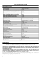
1
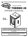
SHERWOOD INDUSTRIES IS AN ENVIRONMENTALLY RESPONSIBLE COMPANY. THIS MANUAL IS PRINTED ON RECYCLED PAPER. PLEASE KEEP THESE INSTRUCTIONS FOR FUTURE REFERENCE PELLET STOVE EF THERMO 28 OWNER’S MANUAL ���� PLEASE READ THIS ENTIRE MANUAL BEFORE INSTALLATION AND USE OF THIS PELLET-BURNING ROOM HEATER. FAILURE TO FOLLOW THESE INSTRUCTIONS COULD RESULT IN PROPERTY DAMAGE, BODILY INJURY OR EVEN DEATH. Contact your building or fire officials about restrictions and installation inspection requirements in your area. 50-877 Table of Contents Introduction........................................................................................3 Important Safety Data...............................................................3 Water Specifications..................................................................4 Pellet Quality............................................................................4 Warnings and Recommendations...............................................5 Rating Label Location................................................................6 Appliance Dimensions...............................................................6 Operating Instructions.........................................................................7 Control Board Functions............................................................7 Turning Pellet Stove On.............................................................7 Turning Off Your Pellet Stove.....................................................8 Slider/Damper Operation...........................................................8 Routine Cleaning and Maintenance.......................................................9 Troubleshooting.................................................................................12 Warranty...........................................................................................14 Installation Data Sheet.......................................................................15 This manual is to be used by the owners for safety and operating instructions. 2 Introduction IMPORTANT SAFETY DATA: Please read this entire manual before installation and use of this pellet fuel burning room heater. Failure to follow these instructions could result in property damage, bodily injury or even death. CAUTION: DO NOT CONNECT TO ANY AIR DISTRIBUTION DUCT OR SYSTEM. DO NOT BURN GARBAGE OR FLAMMABLE FLUIDS SUCH AS GASOLINE, NAPTHA OR ENGINE OIL. UNIT HOT WHILE IN OPERATION. KEEP CHILDREN, CLOTHING AND FURNITURE AWAY. CONTACT MAY CAUSE SKIN BURNS. Contact local building officials about restrictions and installation inspection requirements in your area. The stove’s exhaust system works with negative combustion chamber pressure and a slightly positive chimney pressure. It is very important to ensure that the exhaust system be sealed and airtight. The use of grates or other methods of supporting the fuel is not permitted. This unit is designed to burn pelletized wood fuel only. Do not use any other type of fuel, this will void any warranties stated in this manual. THE USE OF CORDWOOD IS PROHIBITED BY LAW. Do not burn with insufficient combustion air. A periodic check is recommended to ensure proper combustion air is admitted to the combustion chamber. Setting the proper combustion air is achieved by adjusting the slider/damper located on the left side of the stove. It is advisable to clean the exhaust vent bi-annually or every two tons of pellets. The grounded electrical cord should be connected to a standard 220-240 volts, 50 hertz electrical outlet and also must be accessible. If this power cord should become damaged, a replacement power cord must be purchased from the manufacturer or a qualified ENVIRO dealer. Be careful that the electrical cord is not trapped under the appliance and that it is clear of any hot surfaces or sharp edges. This unit’s maximum power requirement is 800 watts (3.3 amp). Soot or creosote may accumulate when the stove is operated under incorrect conditions such as an extremely rich burn (black tipped, lazy orange flames). If the creosote is ignited it will make an extremely hot fire, therefore, the smoke pipe and chimney should be inspected regularly to determine if a build-up has occurred. If creosote has accumulated it should be removed to reduce the risk of a chimney fire. If a fire occurs throw a cup of water into the firebox, close the door, and call the fire department. When installing the stove in a mobile home, it must be electrically grounded to the steel chassis of the home and bolted to the floor. Make sure that the structural integrity of the home is maintained and all construction meets local building codes. Be sure to maintain the structural integrity of the home when passing a vent through walls, ceilings, or roofs. IMPORTANT: The ash pan and viewing door must be locked securely for proper and safe operation of the pellet stove. If you have any questions with regards to your stove or the above-mentioned information, please feel free to contact your local dealer for further clarification and comments. Since Sherwood Industries Ltd. has no control over the installation of your stove, we grant no warranty implied or stated for the installation or maintenance of your stove. Therefore, Sherwood Industries Ltd. assumes no responsibility for any consequential damage. 3 Introduction WATER SPECIFICATIONS: Necessary draught 34.8 Pa (0.348 mbar) Mass of Appliance 157 Kg Minimum required load bearing capacity of the floor 247 Kg Water content 17.3 liters Exhaust gas temperature at nominal heat output 230°C Exhaust gas temperature at minimum heat output 120°C Exhaust mass flow at nominal heat output 7.5 g/s Exhaust mass flow at minimum heat output 8.0 g/s Flue pipe diameter 80 mm Space heating output to be determined by Lab Testing KW Water heating output to be determined by Lab Testing KW Nominal heating output 25 kW Heat output range 2.5 kW - 25 kW Combustion period at QN 12 hours Setting range for the temperature controller 30°C - 75°C Fuel (type, size, water content) Wood pellets, 6 mm dia. maximum, <8% W.C. Hopper capacity 77.75 liters (55 Kg) Hopper filing opening 440 mm x 320 mm Auxiliary power requirements 800 W Test pressure 4.5 bar Operating pressure 0.5 bar - 2.5 bar Maximum water pressure 3.0 bar Maximum water temperature 90°C Burn Rate 1.0 - 4.5 Kg/hr Maximum Power Requirement 800 watts Voltage Rating Range 220-240 volt at 50 Hz Amperage Rating 3.3 Amp Table 1 PELLET QUALITY: PELLET QUALITY IS IMPORTANT, PLEASE READ THE FOLLOWING PAGE. Your pellet stove has been designed to burn wood pellets only. Since there are many manufacturers of wood pellets, it is important to select pellets that are free of dirt or any impurities. Ask your dealer for a recommended pellet type. THE PERFORMANCE OF YOUR PELLET STOVE IS GREATLY AFFECTED BY THE TYPE AND QUALITY OF WOOD PELLETS BEING BURNED. AS THE HEAT OUTPUT OF VARIOUS QUALITY WOOD PELLETS DIFFER, SO WILL THE PERFORMANCE AND HEAT OUTPUT OF THE PELLET STOVE. Since Sherwood Industries Ltd. has no control over the quality of pellets that you use, we assume no liability caused by the quality of wood pellets used. 4 Introduction Check the burn-pot liner periodically to ensure that the holes are not blocked with clinkers, (clinkers are silica in the fuel that form a hard mass during the burning process). If they are blocked, remove the liner (when the unit is cold) and clean the clinkers out. The liner should be cleaned or scraped once every 2-3 days depending on wood pellet quality. Clean the holes in the liner with a small pointed object. Store pellets at least 36” (1 m) away from the pellet stove. WARNINGS AND RECOMMENDATIONS: A. Do not abuse the glass by striking or slamming the door shut. B. Do not attempt to operate the stove with broken glass. C. Do not attempt to open the door and clean the glass while the unit is in operation. To clean the glass, use a soft cotton cloth and mild window cleaner, gas or wood stove glass cleaner, or take a damp paper towel and dip into the fly ash. This is a very mild abrasive and will not damage the glass. D. Do not use abrasive cleaners to clean the surface or any part of the stove. E. It is recommended that the unit be secured into its position in order to avoid any displacement. F. Never use gasoline, gasoline-type lantern fuel, kerosene, or similar liquids to start the fire. Keep all such liquids well away from the pellet stove while it is in use. G. Disposed ashes should be placed in a metal container with a tight-fitting lid. The closed container of ashes should be on a non-combustible floor on the ground, well away from all combustible materials pending final disposal. The ashes should be retained in the closed container until all cinders have thoroughly cooled before disposing of them. H. Make sure the ash pan is closed tightly during the operation of the stove. I. Fresh air intake is strongly recommended. Failure to install intake air may result in the unit smoking during power failures as well as improper combustion. J. Do not operate at water pressure below 0.5 bar. NOTE: Fresh air is mandatory on all units installed in “Mobile Homes” and “Air Tight” homes. KEEP ASH PAN FREE OF RAW FUEL. DO NOT PLACE UNBURNED OR NEW PELLET FUEL IN ASH PAN. A fire in the ash pan could be the result. In the event of a malfunction, turn the water heater feed OFF. Push the ON/OFF button located on the control panel. Have the water heater inspected and serviced by a qualified service technician. - Have your unit and venting checked/cleaned/serviced annually by a qualified service technician to prevent excess build-up of dangerous creosote deposits as well as to ensure proper operation and efficiency of this appliance. IMPORTANT: The heated water from this unit is not for human consumption, but for heating potable water through heat exchange only. WARNING: No modifications can be preformed to this appliance prior authorization from the manufacturer. Use only Enviro approved replacement parts 5 Introduction RATING LABEL LOCATION: The rating label is located on the hopper lid. APPLIANCE DIMENSIONS: UNIT DIMENSIONS HEIGHT: 37 3⁄8” (949 mm) WIDTH: 25 1⁄4” (641 mm) DEPTH: 25 7/16” (646 mm) HEARTH PAD: WIDTH: 25 1⁄4” (641 mm) DEPTH: 31 3/16” (793 mm) [6” (152.4 mm) in front of unit] 37 3/8" (94.9cm) 25 7/16" (64.6cm) 25 1/4" (64.1cm) Figure 1 ���� ���� ����� ��� ����� ������ ����� ���� �� ����� ������ ����� ��� ������ ������� �� ������ ������ �� ���� ������ ���� ���� �� ���� ������ � ���� ������ � ���� ������ � ������ ������ � ���� ����� � ���� ������ Figure 2 6 � ���� ������ Operating Instructions CONTROL BOARD FUNCTIONS: 1. WATER TEMPERATURE DIAL: Read in degrees Celsius 2. AUGER TRIM � 3. CONVECTION BLOWER CONTROL 4. AUGER PULSE LIGHT: The light flashes in conjunction with the auger. 5. MANUAL AUGER FEED: If the unit runs out of fuel, this button can be used to “prime the auger system”. This button will turn off after 60 seconds and then must be released and pressed again. � � � � � � � � 6. SYSTEM LIGHT: If flashing, the board is under control. If the light is solid, setting can be altered. 7. ON/OFF BUTTON 8. HEAT OUTPUT INDICATOR: Shows the present heat output setting. 9. HEAT LEVEL ADJUSTMENT: When pressed, will change the heat setting of the unit from low to high. NOTE: This unit is capable of continuous operation if the heat demand is high enough to require the unit to stay on. Figure 3 TURNING PELLET STOVE ON: Ensure the hopper has sufficient pellet fuel to start the unit. 1. Set water temperature, using the rotary dial located above the feed controls. 2. Press the ON / OFF button to start the appliance. System light will flash, auger light will flash with the pulse of the auger, heat level indicator will show the start up heat setting with no control for the operator until the system light becomes solid. 3. If this is the first time the unit has been started or the unit has run out of fuel, press the Manual Auger Feed button and hold down for 60 seconds. This will help “prime the auger,” deliver fuel to the burn pot, and help light the unit more quickly. 4. When a fire has been established, the system light will become solid and the auger light will continue to flash. The heat output button can be pressed to achieve the desired heat setting. 7 Operating Instructions 5. The convection blower (room air blower) will be on, the speed of this blower is controlled by the setting set on the heat output indicator. The convection blower can be turned OFF by depressing the convection blower control button. It is recommended that the convection blower be left on at all times. 6. When unit is operating on LOW the unit can be adjusted for poorer quality fuels. By depressing the Auger Trim button, WHEN THE UNIT IS ON LOW, the ON time the auger pulses can be changed from 2 seconds ON to 4 seconds ON. AUGER TRIM 2 SECONDS “ON” AUGER TRIM 3 SECONDS “ON” Factory Setting AUGER TRIM 4 SECONDS “ON” These settings can be used if the unit does not keep a fire going on low (poor quality fuel). These settings could also be used if the low setting is too hot or cold for the surrounding area. 7. Set water and/or room thermostats to desired temperature(s). Figure 4 TURNING OFF YOUR PELLET STOVE: To turn the unit OFF, simply press the ON / OFF button. All LED lights will go out. This will stop the feed of pellets. The blowers will continue to operate and cool the stove. When cool enough, the stove will shut down. NOTE: During the 15 minute start-up sequence the stove can not be turned off by turning the water temperature dial down. If the dial is turned down, the stove will run through its complete start-up sequence and shut down after the stove has lit. The unit can be shut-off manually at this time by pressing the ON/OFF button. SLIDER/DAMPER OPERATION: This is used to regulate the airflow through the pellet stove. • On the low heat output settings, push the slider all the way in. ���� ��� • On the high heat output pull the slider out or until a good fire is achieved. A good fire is in between a fire with lazy black tipped flames and a forced fire (very quick, shorter flames). A good fire is the most efficient and will have a bright and active flame. ���� ��� • Slider should be set at a hot magnehelic reading of 0.14” W.C. (34 Pa) for firebox vacuum. Figure 5 8 Routine Cleaning and Maintenance The following list of components should be inspected and maintained routinely to ensure that the appliance is operating at its’ optimum and giving you excellent heat value: TOOLS REQUIRED TO CLEAN UNIT: Torx T-20 Screwdriver, 5/16” wrench or socket, 75 mm and 50 mm Brush, Soft Cloth, Vacuum with fine filter bag. ASH PAN AND DOOR GASKETS (Check every 2-3 days): 2-3 DAYS/WEEKLY Ash Pan and Door Gaskets Above Heat Exchanger Tubes Burn Pot and Liner Ash Pan Door Glass Inside Firebox Door Latch 1⁄2 SEASON or 1 TON OF FUEL Exhaust Vent Fresh Air Intake Tube Blower Mechanisms Inside Heat Exchanger Tubes Internal exhaust Box All Hinges After extended use, the gasketing may come loose. To repair this, glue the gasketing on using high-temperature fiberglass gasket glue available from your local dealer. This is important to maintain an airtight assembly. DO NOT PLACE UNBURNED OR RAW PELLET FUEL IN ASH PAN. ABOVE HEAT EXCHANGER TUBES (Every 2-3 days): There is a tube cleaner rod at the front of the unit (shown in Figure 6). When the stove is off, pull the rod in and out to remove the ash build up above the heat exchanger tubes. BURNER POT AND LINER (Every 2-3 days): To remove the burn pot and burn pot liner, open the door. Swing the door open. Lift the liner from the burn pot. Lift the burn pot from the firebox by gently lifting up the front of the burn pot, then sliding the assembly from the air intake tube and the ignitor cartridge. This is the ‘pot’ where the pellets are burned. Every two to three days (when the unit is cold), remove the burn-pot liner from the stove. Using a metal scrapper, remove material that has accumulated or is clogging the liner’s holes. Then dispose of the scrapped ashes from the liner and from inside the burn-pot. Place the burn-pot back into the stove, making sure that the pipes are properly inserted into the burn pot. Place the liner back into the burn-pot, making sure that the ignitor hole in the liner is aligned with the ignitor tube. Push the liner up against the ignitor tube. Figure 6 Burn pot liner Fresh air tube Ignitor tube Burn pot Figure 7 ASH REMOVAL: CAUTION WHEN VACUUMING FLY ASH: BECAUSE THE FLY ASH IS VERY FINE, THE USE OF A FINE FILTER VACUUM BAG WILL BE REQUIRED TO PREVENT ASH FROM BEING BLOWN BACK INTO THE ROOM. Please pay special attention that there are no hot ashes in the firebox or there could be a possibility of a fire hazard inside the vacuum cleaner. Place all hot ashes into a non-combustible container. 9 Routine Cleaning and Maintenance ASH DRAWER: Remove ash drawer (see Figure 8). Dump the ashes into a metal container stored away from combustibles. Monitor the ash level every week. Remember that different pellet fuels will have different ash contents. Ash content is a good indication of fuel efficiency and quality. Refer to “Warnings and Recommendations” for disposal of ashes. DO NOT PLACE UNBURNED OR RAW PELLET FUEL IN ASH PAN. Ash drawer Ash drawer cover INSIDE FIREBOX For bi-weekly clean out, ash may be removed from the heat exchange tube by cleaning with a 50 mm round brush. BLOWER MECHANISMS: Unplug the stove then open the right/left side panels to access the two (2) blowers. Clean debris from guards DO NOT lubricate the motors. Figure 8 DOOR GLASS Do not attempt to open the door and clean the glass while the unit is in operation or if glass is hot. To clean the glass, use a soft cotton cloth and mild window cleaner, gas or wood stove glass cleaner, or take a damp paper towel and dip into the fly ash. This is a very mild abrasive and will not damage the glass. It is recommended that your dealer replace the glass if broken. The door glass is made of 5 mm thick, high temperature PYROCERAMIC. The center panel is 229 mm x 330 mm (9” x 13”). To replace the glass, unscrew and remove the four glass retainers. Remove the glass and any broken pieces. High temperature fiberglass tape should be used around the glass. Replace the glass, center the glass assembly in the frame, then screw the glass retainers back to the frame. The use of substitute materials is prohibited. FRESH AIR INTAKE Inspect prior to relighting after a prolonged shut down period and periodically through the burning season to be sure that the fresh air intake is not clogged with any foreign materials. Ensure that the air intake grills are not blocked. EXHAUST VENT Soot and Fly-ash: Formation and Need for Removal - The products of combustion will contain small particles of fly-ash. The fly-ash will collect in the exhaust venting system and restrict the flow of the flue gases. Incomplete combustion, such as occurs during startup, shutdown, or incorrect operation of the room heater will lead to some soot formation which will collect in the exhaust venting system. The exhaust venting system should be inspected prior to relighting after a prolonged shut down period and at least once every half (1⁄2) year or after one (1) tons of pellets to determine if cleaning is necessary. The chimney must be scrubbed with the appropriate sized steel brush; we recommend contacting your dealer for professional cleaning. To remove dust from the vent pipe, tap lightly on the pipe to dislodge any loose ash. Open the bottom of the “T” to dump the ash, then vacuum as much of the ash out of the vent pipe as possible. POST SEASON CLEAN-UP Once you are finished using the pellet appliance for the season, unplug the stove for added electrical protection. It is very important that the stove be cleaned and serviced as stated above. 10 Routine Cleaning and Maintenance HEAT EXCHANGER AND INTERNAL EXHAUST TUBES: ONLY TO BE CLEANED WHEN THE UNIT IS COLD. Clean away any fly ash that may have collected in and on the tubes. As different types of pellets produce different amounts of ash, cleaning of the tubes should be done on a regular basis to enable the unit to run efficiently. 1. Remove the top by loosing the two (2) screws at the back and remove the two (2) under the hopper lid shown in Figure 9. Pull the top up at the back and slide it forward. 2. Remove the cab sides by loosing the three (3) T-20 screws on the back of each side (see Figure 9). Remove the ash drawer cover and ash drawer (see Figure 8) then remove the T-20 screws from the two (2) front tabs (see Figure 10) . 3. Remove the heat exchanger cover from the top of the stove by removing the screw on each side shown in Figure 11. 4. With the heat exchanger cover removed, the heat exchanger tubes can be cleaned. Scrub the top surface of the heat exchanger. 5. Clean the tubes referred to in Figure 12 as #1; one on each side. Use a 3” (75 mm) cleaning brush to scrub the tubes from top to bottom until buildup is removed. 6. Clean the tubes referred to in Figure 12 as #2; nine total. Use a 2” (50 mm) cleaning brush to scrub the tubes from top to bottom until all Figure 10 buildup is removed. 7. With the cab sides removed, you will see a clean-out cover on each side Figure 9 (see Figure 11), remove the two (2) � T-20 screws from � the cover. Vacuum out all ash from behind the cover. 8. Open the door and scrub the inside of the firebox. 9. Vacuum up all loose ash that has been brushed off from all areas. 10. Re-install the cleanout covers, the heat exchanger cover, the cab sides and the top. Figure 11 Figure 12 11 Troubleshooting *NOTE: All troubleshooting procedures should be carried out by qualified technicians or installers. DO NOT: • Hold the ON / OFF BUTTON; this is a momentary contact switch and can be damaged if held down too long. • Service the stove with wet hands. The stove is an electrical appliance, which may pose a shock hazard if handled improperly. Only qualified technicians should deal with possible internal electrical failures. • Do not remove any screws in the firebox without first lubricating them with penetrating oil. WHAT TO DO IF: 1. 2. 3. 4. 5. 6. 7. The stove will not start. The stove will not operate when hot. The convection blower will not function normally. Control settings (heat level) have no effect on fire. The stove will not shut off. The stove keeps going out. The #2 light is flashing on the heat level indicator light 1. The stove will not start. üMake sure the stove is plugged in and the wall outlet is supplying power. üPush the ON /OFF button. üIf the Control Board has been placed in the ON /OFF thermostat mode, then turn the thermostat up to call for heat. üIf the unit still does not start, contact your local service dealer for service. 2. The stove will not operate when hot. «Check the hopper for fuel. «Poor Quality Fuel – Insufficient energy in the fuel to produce enough heat to keep the stove burning or operational. «The third red LED light in the heat level indicator light will flash if a fire is not detected or if the fire has gone out. «The unit may require cleaning. Contact your local dealer for service. «Contact your local dealer for additional troubleshooting. 3. The convection blower will not function normally. «Clean all grill openings at the back and below unit. «Press the fan button. Does the fan come on? Press again to verify that the blower turns on; if not, contact your local dealer for service. 4. Control settings (Heat Level) have no effect on the fire. NOTE: If the system light is flashing, the Control Board has complete control of the unit. When the unit’s system light becomes solid, then control of the unit is given back to the operator. üIf there is no control of the Heat Level button, make sure the thermostat is calling for heat. üCall your local dealer for service. 12 Troubleshooting 5. The stove will not shut off. «If the unit will not shut off, ensure that the thermostat (if equipped) is turned down below the room temperature (thermostat mode in the ON / OFF position). «If the unit is in the HI/LOW mode the unit will not shut off but will go to an idle setting (LOW). Press the ON/OFF button to turn the unit off. 6. The stove keeps going out. If the stove goes out and leaves fresh unburned pellets or cigarette-like ashes in the burn pot liner, the fire is going out before the stove shuts off. üCheck to see that the Slider / Damper is in the correct position. üTurn the Heat Level up slightly (poor quality pellets will require slightly higher settings). üSet the auger trim till the #1 and #5 lights are illuminated. If the stove goes out and there are partially burned pellets left in the burn pot liner, the stove has shut down due to a lack of air, exhaust temperature, or power failure. «Adjust the Slider / Damper. «Check to see if the stove needs a more complete cleaning. «Did the power go out? «Turn the Heat Level up slightly (poor quality pellets will require slightly higher settings). «Contact your local Dealer for service. 7. The #2 light is flashing on the heat level indicator light (see #8 in Figure 3). «The water temperature high limit switch has tripped. Remove right cabinet side and manually reset the high limit switch. «The low water pressure switch has tripped. Increase the water pressure in the system. To reset Circuit Board after a trouble code - push the ON/OFF button. 13 Warranty Sherwood Industries Ltd. gives a five year limited warranty on all steel manufactured parts. A one-year warranty is provided on all electrical components. The above limited warranties are extended only to the original purchaser. There is no warranty on the following parts: ● Glass window ● Fiberglass rope gaskets ● refractory material ● burn pot liner ● paint ● enamel finish or gold plating where it applies **NOTE: The paint on the brick firebox lining may peel. This is due to the extreme conditions applied to the paint and is in no way covered under warranty. WHEN FILING A WARRANTY CLAIM PLEASE COMPLETE THE FOLLOWING INFORMATION ON AN OFFICIAL WARRANTY CLAIM FORM: TO THE DEALER: - Name and address of dealer, - Date of purchase - Name, address and telephone number of purchaser - Name, address and telephone number of installer - Date of installation, and - Serial number of the appliance Ensure that you specify the nature of the complaint, defect, periodical malfunction, etc. TO THE DISTRIBUTOR: - Sign and verify that work and information are correct. - Description and part # of any parts replaced. The limited warranty covers defects in materials and workmanship as long as the products has been installed according to the manual’s instruction. If the product is damaged or broken as a result of mishandling or misuse, the warranty does not apply. Removal and re-installation costs are not covered under this warranty. It is the manufacturer’s option whether to repair or replace the appliance. The shipping cost to and from the factory is to be paid by the consumer. All warranties by the manufacturer are set forth herein and no claim shall be made against the manufacturer on any oral warranty or representation. The manufacturer assumes no responsibility for damage caused by household power fluctuations or power surges. Under Warranty For the do-it-yourself Individual The consumer should be aware that the pellet appliance needs setting using tools that he/she might not have. It is recommended that you have a qualified installer install your pellet appliance Sherwood Industries Ltd. reserves the right to make changes without any notice. 14 Installation Data Sheet The following information must be recorded by the installer for warranty purposes and future reference. NAME OF OWNER: NAME OF DEALER: _________________________________________ _________________________________________ ADDRESS: ADDRESS: _________________________________________ _________________________________________ _________________________________________ _________________________________________ _________________________________________ _________________________________________ PHONE:___________________________________ PHONE:___________________________________ MODEL:___________________________________ NAME OF INSTALLER: SERIAL NUMBER:___________________________ DATE OF PURCHASE: _____________ _________________________________________ (dd/mm/yyyy) DATE OF INSTALLATION:___________(dd/mm/yyyy) ADDRESS: MAGNEHELIC AT INSTALL:___________________ _________________________________________ INSTALLER’S SIGNATURE: _________________________________________ _________________________________________ _________________________________________ PHONE:___________________________________ MANUFACTURED BY: SHERWOOD INDUSTRIES LTD. 6782 OLDFIELD RD. SAANICHTON, BC, CANADA V8M 2A3 www.envirofire.biz February 24, 2005 C-10821 15