1
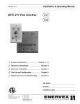
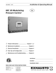
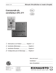
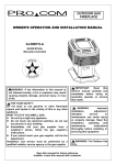
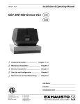
Installation & Operating Manual
3002503 11.06
RSIB 300-500
Power Venter
USA
CAN
Product Information........................ Chapters 1 + 2
Mechanical Installation ......................... Chapter 3
Electrical Installation ............................. Chapter 4
Start Up and Configuration .................. Chapter 5
Maintenance and Troubleshooting ...... Chapter 6
ERTEK
INT
Job Name:
CM
C
LISTED
Installer:
US
Installation Date:
READ AND SAVE THESE INSTRUCTIONS!
EXHAUSTO Inc.
1200 Northmeadow Pkwy.
Suite 180
Roswell, GA 30076
P: 770.587.3238
F: 770.587.4731
T: 800.255.2923
[email protected]
us.exhausto.com
3002503 11.06
1. Product Information
1.1 Function................................................................................................3
1.2 Components..........................................................................................3
1.3 Shipping................................................................................................4
1.4 Warranty................................................................................................4
2. Specifications
2.1 Dimensions & Capacities.......................................................................5
3. Mechanical Installation
3.1 General.................................................................................................6
3.2 Positioning............................................................................................6
3.3 Mounting of Power Venter....................................................................7
3.4 Connection to Chimney or Vent............................................................8
3.5 Connection to Flexible Duct..................................................................8
4. Electrical Installation
4.1 General.................................................................................................9
4.2 Wiring Diagram - RSIB 300...................................................................9
4.3 Wiring Diagram - RSIB 350-500..........................................................10
4.4 Installing a Proven Draft Switch ......................................................... 11
4.5 Installation of Stack Probe for PDS Function...................................... 11
4.6 Checking and Changing Rotation on RSIB 350, 400 and 500............12
5. Startup and Configuration
5.1 General...............................................................................................13
5.2 System Testing....................................................................................13
5.3 Adjusting Fan Speed...........................................................................13
5.4 Testing Safety System.........................................................................13
6. Maintenance and Troubleshooting
6.1 General...............................................................................................14
6.2 Preparing the Power Venter for Cleaning............................................14
6.3 Troubleshooting...................................................................................15
Symbol Legend:
The following terms are used throughout this manual to bring attention
to the presence of potential hazards, or to important information
concerning the product.
Danger: Indicates an imminent hazardous situation
which, if not avoided, will result in death, serious injury or
substantial property damage.
!
!
Caution: Indicates an imminent hazardous situation
which, if not avoided, may result in personal injury or
property damage.
TO REDUCE THE RISK OF FIRE, ELECTRICAL SHOCK OR INJURY TO PERSONS,
OBSERVE THE FOLLOWING:
5. This unit must be grounded.
1. Use this unit in the manner intended by the manufacturer. If you have questions, contact the manufacturer at the address or telephone number listed on the front of the manual.
2. Before servicing or cleaning the unit, switch off at service panel and lock service panel to prevent power from being switched on accidentally.
3. Installation work and electrical wiring must be done by a qualified person(s) in accordance with applicable codes and standards.
4. Follow the appliance manufacturer’s guidelines and safety standards such as those published by the National Fire Protection Association (NFPA), and the American Society for Heating, Refrigeration and Air Conditioning Engineers (ASHRAE), and the local code authorities.
How to use this manual
This installation manual does not contain any system design
documentation. System design documentation is available from any
authorized EXHAUSTO representative.
Accessories, fans, and variable frequency drives are not covered by
this manual. Please refer to these component’s individual manuals.
3002503 11.06
1. Product Information
1.1 Function
Use
The EXHAUSTO RSIB Power Venter is intended for use as an in-line draft inducer/power venter. It can be installed in-line with the chimney or stack, and can be used in sidewall and vertical venting arrangements. It is specifically designed for applications requirinng efficient operation, low noise level, low energy consumption, variable speed and compact design. The RSIB is for use with non-condensing and condensing appliances (Category I, II, III, IV) operating at flue gas temperatures at or below 575°F (300° C). Typical uses include, but are not limited to, mechanical venting of gas and oil fired boilers and water heaters and other appliances operating with discharge temperatures at or below 575°F (300° C). The RSIB is for indoor and outdoor installations.
Construction The EXHAUSTO RSIB Power Venter is an efficient high temperature ventilator with a backward-inclined, cast aluminum impeller. The ventilator housing is made of corrosion resistant 316L stainless steel. It is equipped with an energy-efficient, totally enclosed, variable speed motor, which is mounted outside the air stream. A motor mounting plate on the front of the ventilator provides easy access to the inside of the fan and the duct connections. The motor and impeller are mounted on the motor mounting plate which is secured to the fan housing with six bolts. The stack connections are of the slip connection type. The ventilator can be mounted on vibration insulated support legs or from ceiling mounting brackets.
Listings The RSIB model is tested and listed to UL378, Standard for Draft Equipment, UL705, Standard for Power Venters, and CSA-CAN3-B255-M81, Mechanical Flue Gas Exhausters. The Canadian listing does not cover use with condensing appliances. This installation manual does not contain any system design documentation. Please refer to the system design manuals or instructions by EXHAUSTO. The RSIB is a component in the CASI, Chimney Automation System.
Restrictions The RSIB Power Venter should only be used with appliances operating on Natural Gas, LP-Gas/Butane or fuel oil (#2 through #6). It should never be used with incinerators, incinerating toilets or solid-
fuel burning equipment. When used with multiple appliances and utilizing a Fan Speed Control or a Variable Frequency Drive to control the fan speed, a barometric damper should be installed to prevent overdraft conditions, unless the appliance(s) has a draft hood or a draft diverter. This limitation does not apply when used with an EBC 12 or EBC 30, Pressure Control. The temperature of the flue gases going through the Power Venter should never exceed 575°F (300°C).
1.2 Components
Fig. 1
Outlet
Mounting
legs
Motor Mounting
Plate
Mounting eyes
and holes
Motor
3002503 11.06
1.3 Shipping
Standard packing list
The RSIB contains the following:
• The RSIB is shipped with two integrated sets of mounting brackets for use when hung from the ceiling.
If other components are shipped, these will appear as separate items on the shipping packing list.
1.4 Warranty
Complete warranty conditions are available from EXHAUSTO, Inc.
3002503 11.06
2. Specifications
2.1 Dimensions & Capacities
Model
RSIB 300
Fan Type
Motor Type
Amperage
VAC
1 x 120
Amps
5.8
RSIB 500
3 x 200-240 / 3 x 440-480
3.6 / 1.7
6.5 /2.9
9.0 / 4.0
Output HP
0.5
1.0
2.0
3.0
kW
0.35
0.75
1.5
2.2
RPM
1600
Duct Connection
(Nominal)
Dimensions
RSIB 400
TEFC (Class H)
Voltage
Motor
RSIB 350
Centrifugal Impeller (B-wheel)
in
1740
14
16
20
mm
300
350
400
500
in
19.9
16.9
21.9
22.2
mm
506
430
557
564
in
4.8
5.6
6.5
6.2
mm
122
143
164
158
in
4.0
3.9
5.4
4.6
A
B
C
mm
102
98
138
116
in
11.8
13.8
15.8
19.8
mm
300
351
402
503
in
11.8
9.1
11.2
12.7
mm
299
231
286
323
D
E
F
in
10.5
11.3
13.3
14.8
mm
267
287
337
375
G
in
10.1
12.1
13.7
14.6
mm
256
307
348
370
H
J
12
in
35.9
35.9
43.5
46.7
mm
912
912
1106
1186
in
mm
5.3
5.9
7.0
7.4
135
150
178
188
34.3
L
in
25.8
25.8
34.3
mm
654
654
870
870
in
27.0
28.8
32.6
36.3
mm
686
733
827
922
lbs
70
84
132
170
kg
32
38
60
77
W
Weight
Capacity:
Pt (inW.C.)
5.0
4.5
4.0
3.5
RS
IB
3.0
50
0
IB
RS
2.5
0
40
IB
RS
2.0
0
35
IB
RS
1.5
30
0
1.0
0.5
0.0
Easy access to inside of fan
Prepared for ceiling mounting
Cast-aluminum impeller
0
1000
2000
3000
Volume (cfm)
4000
5000
6000
3002503 11.06
3. Mechanical Installation
3.1 General
Warning: Failure to install, maintain and/or operate the RSIB Power Venter in accordance with
the manufacturer’s instructions may result in conditions which can produce bodily injury and
property damage.
The RSIB must be installed by a qualified installer in accordance with these instructions and all local codes, or in their absence, with the latest edition of The National Fuel Gas Code (NFPA54/ANSI223.1), NFPA 211, NFPA 31
or Canada CAN/CSA-B149.1-05 National Gas and Propane Installation Code when applicable. The RSIB must be mounted so the clearance to combustibles is at least 24 inches.
Preferably, the RSIB should be installed as close to the termination as possible. It can also be installed near the
outlet of a heating appliance in the breeching itself, or in the transition from breeching to vertical chimney (replacing the Tee). In addition, it can be used for sidewall vented applications where it discharges through a wall. The RSIB contains two drain holes to allow condensation to exit the fan housing.
The RSIB is for indoor and outdoor installation. Unless installed adjacent to the wall it is discharging through, the chimney material used on the discharge side must be airtight/pressure rated. Traditional gas vent (B-vent) is not considered pressure rated or airtight. The vent pipe must be installed and supported according to the chimney manufacturer’s instructions and/or in accordance with NFPA54, NFPA211 and Canada CAN/CSA-B149.1-05. The RSIB collars fit most commonly available vents and stacks.
3.2 Positioning
The power venter can be installed in multiple positions. However, it should always be possible to remove the access door.
Acceptable power venter positions are shown below in Fig. 2. Note that the power venter should never be installed so the motor points down. This will cause condensation build up around the motor shaft and shorten the life of the motor.
RSIB350-500: A drain hole located at the base of the motor MUST be removed prior to installation. Failure to do so could shorten the life of the motor. See Fig. 2 below.
Warning! Never install the power venter so the motor points down. This will shorten the life. The
min. clearance to combustibles is 24 inches.
Fig. 2
3002503 11.06
The figure below shows typical installation arrangements:
Fig. 3
Vertical
Venting
Sidewall
Venting
3.3 Mounting of Power Venter
The power venter can be installed in a variety of positions. It can be suspended from a ceiling or placed on a shelf/floor. Placement on a shelf requires special hardware and vibration dampers.
Suspension from a ceiling does not require any special hardware other than threaded rods, nuts, and hangers.
Fig. 4
Threaded rod
Follow Fig. 4 and 5. when suspending the power venter from a ceiling. Fig. 4 shows which mounting legs to use when installing the power venter in its normal position with inlet in the back and outlet on the top (installation between horizontal and vertical chimney). Fig. 5 shows which mounting legs to use when installing the power venter with inlet on the bottom and outlet on the side (installation for sidewall venting).
1. Once the position has been determined, hang four threaded rods from hangers above, and slide the rods through the mounting holes in the mounting legs.
2. Level the power venter.
3. Secure the legs with washers and nuts.
Nuts
Mounting legs
Fig. 5
UP
Mounting
legs
Threaded
rods
Warning! Never install the power venter so the motor
points down. This will shorten the life. The min.
clearance to combustibles is 24 inches.
UP
Nuts
3002503 11.06
3.4 Connection to Chimney or Vent
Follow the recommendations by the vent or stack manufacturer. For optimal performance, the distances in Fig. 6 should be observed.
Fig. 6
3xD
D
3xD
D
3.5 Connection to Flexible Duct
Flexible duct (FLF) is used to reduce the effects of pulsating appliances on the fan and duct system. If used, the FLF should be connected between the fan inlet/ outlet and the main vent or stack as shown in Fig. 7. This will decrease vibration in the system and prevent deflection of the fan housing.
Fig. 7
3xD
D
FLEXIBLE DUCT
CONNECTION
D
3xD
3002503 11.06
4. Electrical Installation
4.1 General
Danger: Turn off electrical power before servicing. Contact with live electric components can cause shock or death.
!
Notice: If any of the original wire supplied with the system must be replaced, use similar wire of the same temperature rating. Otherwise, insulation may melt or degrade, exposing bare wire.
All wiring must be in compliance with the local codes or in their absence, the National Electric Code, NFPA70. All wiring should be appropriate Class 1 wiring as follows: installed in rigid metal conduit, intermediate metal conduit, rigid non-metallic conduit, electrical metallic tubing, or be otherwise suitably protected from physical damage.
RSIB models operate at different voltages, so it’s important to pay attention to the wiring details. RSIB 300 operates at 1x120VAC while all other models can operate at 3x208-230VAC or 3x440-480VAC.
4.2 Wiring Diagram - RSIB 300
Power Venter and motor specifications can be found under “Sec. 2.1 Dimensions and Capacities”. The power venter is equipped with a variable speed motor. The diagram below shows a typical wiring diagram for a RSIB 300 utilizing a Fan Speed Control.
Fig. 8
3002503 11.06
4.3 Wiring Diagram – RSIB 350-500
Power Venter and motor specifications can be found under “Sec. 2.1 Dimensions and Capacities”. The power venter is equipped with a variable speed motor. Fig. 9 below shows a typical wiring diagram utilizing a Variable Frequency Drive (adjusting the speed is possible). If it is not a requirement that the speed can be adjusted, a motor starter should be installed in lieu of the VFD, if required by local codes.
Fig. 9
24 VAC
L1 L2 L3 U V W
COM
TR
GREEN
RED
BLACK
VARIABLE FREQUENCY
DRIVE (typical)
WEATHERPROOF BOX
PROVEN DRAFT
SWITCH
BLACK
FAN
MOTOR
HOT
TH
24V GAS VALVE
All wiring must be in
flexible or rigid metal
conduit
POWER SUPPLY
200-240/3/60
or
440-480/3/60
NOTES:
1 THE DISCONNECT MEANS AND CIRCUIT PROTECTION ARE TO
BE PROVIDED BY THE INSTALLER OF THIS DEVICE
LEGEND:
24 VAC
200-240 or 440-480 VAC
RSIB 350-500 can operate at either 3x208-230 VAC or 3x440-480 VAC (default). The motor wiring terminals shown in Fig. 10 shows default jumper positions for 3x440-480VAC operation.
Fig. 10
If the application requires 3x208-240VAC operation, the jumper positions must be changed according to Fig. 11.
Fig. 11
After wiring, make sure the motor is rotating in the proper direction. This is marked on the motor end cover. If the rotation is incorrect, swap the two wires going to the motor terminals, U1 and W1 as shown in paragraph 4.6 . (This does NOT apply to the RSIB 300)
10
3002503 11.06
4.4 Installing a Proven Draft Switch
A safety system must be interlocked with the appliance. The safety system could utilize a Proven Draft Switch
(PDS-1), a thermal switch, a flow switch or a sail switch. The device must be interlocked with the heating appliance(s) so it shuts down in case of insufficient draft, fan failure or power failure. Please refer to the PDS Installation Manual for wiring instructions.
If the installation includes an EBC12 or EBC 30 Fan Control, a PDS-1 is not required as the function is integrated in the control.
For more information about alternative safety system, please consult EXHAUSTO.
4.5 Installation of Stack Probe for PDS Function
Install the probe for the Proven Draft Switch (PDS-1) in the vent connector. The probe must be located between the appliance and the power venter. The probe must be located at least 3 vent diameters downstream of the draft hood, draft diverter, or barometric damper. The probe placement should also observe distances from elbows and Tees as shown in figure below. The tip of the probe MUST be flush with the inner chimney wall to get a proper pressure reading.
Fig. 12
11
3002503 11.06
4.6 Checking and Changing Rotation of RSIB 350, 400, and 500
For a more precise determination, you may also see down inside the fan housing, as shown in Fig.13. The arrow shown (not actually inside fan housing) shows the proper rotation.
It is possible for the fan to operate with improper rotation. However, although some performance can be seen the fan will probably only provide 25-30% of full capacity. Improper rotation wears on the
motor, and causes various electrical faults at the Variable Frequency Drive.
Fan rotation can be changed by swapping the two phase wires as shown on the wiring diagram in Fig.14.
Fig. 14
FAN
MOTOR
VARIABLE FREQUENCY
DRIVE (typical)
L1 L2 L3 U V W
POWER SUPPLY
200-240/3/60
or
440-480/3/60
12
SWAP THESE WIRES ON THE OUTPUT SIDE!
GREEN
RED
Standing in front of the fan with the motor pointing towards you, the rotation must be clockwise. This is indicated by an arrow on the motor end cover. There are holes in the end cover that allow you to see the cooling vanes, but it is difficult to see the rotation unless the fan is running very slowly.
BLACK
Fig. 13
BLACK
To check the rotation of the impeller, it is necessary to be able to see the impeller or the rotation of the cooling vanes at the end of the motor housing.
WEATHERPROOF BOX
3002503 11.06
5. Startup and Configuration
5.1 General
The purpose of this fan is to ensure safe venting for a single appliance or multiple appliances. This can be performed via modulation, or through a single speed where modulation is not required. This is accomplished by starting a chimney fan/power venter when the appliance calls for heat, and stopping the fan when the heat demand has been satisfied.
5.2 System Testing
1. Check the line voltage with the motor name plate rating.
2. Check that the transport securing device (if applicable), holding the motor shaft and impeller in place, has been removed.
3. Determine if the impeller is running free, and has not be subjected to misalignment in shipping or during installation.
4. Apply power, and check that the impeller is rotating in the direction of the arrow on the side of the fan housing (does not apply to RSIB 300). All EXHAUSTO fans run in a clockwise direction when viewed from outside the door.
5. Switching any two phases between the fan and the power source (VFD is the power source if installed) will reverse rotation (except on RSIB 300)
5.3 Adjusting Fan Speed
Start all heating appliances connected to the chimney with the fan installed.
1. If operating with fixed speed, set the fan speed control or the Variable Frequency Drive to the speed where no spillage is experienced anywhere in the system.
2. If operating with variable speed, a modulating control (EBC12, EBC14, or EBC30) is required. Follow the instructions in the control’s installation manual.
5.4 Testing Safety System
Adjust the setting of the Proven Draft Switch or other device used.
Start the heating appliance and the fan, and make sure the safety device is functioning. Turn the fan off. After less than 2 minutes, the appliance should shut down.
13
3002503 11.06
6. Maintenance and Troubleshooting
6.1 General
The power venter is designed for prolonged use, and no regular maintenance is required. It should be inspected periodically (at least once a year), and cleaned, if needed. This specifically applies in case it is being used with fuel oil. The power venter is designed to make this an easy task. The front part of the venter has the motor and impeller mounted on it, and it slides out to provide easy access.
6.2 Preparing the Power Venter for Cleaning
Referring to Fig. 15 below, follow these steps to open the venter so it can be cleaned and inspected:
1. Remove the four bolts holding the front part attached to the mounting legs.
2. Remove the eight bolts on the front part that secures the front to the housing.
3. Slide the front part away from the housing.
4. Clean the impeller wheel and the housing.
5. Reassemble the power venter following the instructions in reverse.
Fig. 15
Mounting
bolts
Front part
Warning: Do not open the housing unless power to the power venter has been disconnected.
14
3002503 11.06
6.3 Troubleshooting
Problem
Possible Cause
Solution
The fan is not
operating
- No power to the fan
- Check the power supply wires in the junction box by the fan.
- Check the circuit breaker.
- Check that the fan is actually turned on.
The fan is not running
at full speed and/or is
humming
- The capacitor is
improperly connected
or not connected at all
(RSIB 300 only)
- Check the connections inside the junction box. The capacitor must be installed
according to the wiring diagram.
The fan is rotating
backwards (except
RSIB 300)
Phase sequence in
the power to the fan is
reversed
- Swap two phases in the junction box.
The fan is vibrating
vigorously
- A transportation
device has not been
removed.
- Foreign matter is
stuck in the impeller.
- A ball bearing is
damaged.
- A balancing weight
has fallen off impeller
- Remove the transportation device.
- Turn off the fan and remove the foreign matter.
- Turn the fan off. After the motor has stopped revolving, spin the impeller and listen
for a grinding noise from the motor. If necessary, replace bearing or entire motor.
- Re-balance impeller or replace it. Check motor for damages.
The fan stops in the
middle of firing cycle
The motor is overheating
Check the flue gas temperature at the fan inlet. The temperature should not exceed
500°F (300°C) during continuous operation. Call EXHAUSTO for advise.
15
3002503 11.06
RSIBEBC
300,12,
350,
EBC400,
14 500
EN60335-1,
DS/EN 292-1, DS/EN
DS/EN 292-2
EN 60 335-1, EN 60
335-2-80,EN60335-2-80,
DS/EN ISO 12100-1:2003,
ISO 12100-2:2003
98/37/EF/-EEC/-EWG/-CEE
98/37/EF/-EEC/-EWG/-CEE
Langeskov, 01.03.2005
EXHAUSTO Inc.
1200 Northmeadow Pkwy.
Suite 180
Roswell, GA 30076
P: 770.587.3238
F: 770.587.4731
T: 800.255.2923
[email protected]
us.exhausto.com