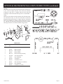
1
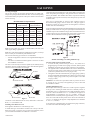
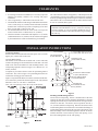
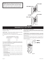
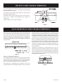
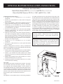
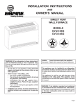
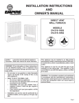
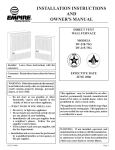
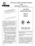
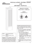
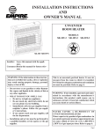
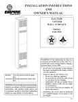
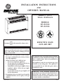
INSTALLATION INSTRUCTIONS
AND
OWNER'S MANUAL
DIRECT VENT
WALL FURNACE
MODELS
DV-25-2SG
DV-35-2SG
Installer: Leave this manual with the appliance.
Consumer: Retain this manual for future reference.
EFFECTIVE DATE
JANUARY 2007
WARNING: If the information in these instructions are not followed exactly, a fire or explosion
may result causing property damage, personal
injury or loss of life.
— Do not store or use gasoline or other flammable vapors and liquids in the vicinity of this or
any other appliance.
— WHAT TO DO IF YOU SMELL GAS
• Do not try to light any appliance.
• Do not touch any electrical switch; do not
use any phone in your building.
• Immediately call your gas supplier from a
neighbor’s phone. Follow the gas supplier’s instructions.
• If you cannot reach your gas supplier, call
the fire department.
— Installation and service must be performed by
a qualified installer, service agency or the gas
supplier.
12434-9-0107
This appliance may be installed in an aftermarket,
permanently located, manufactured home (USA
only) or mobile home, where not prohibited by
state or local codes.
This appliance is only for use with the type of gas
indicated on the rating plate. This appliance is
not convertible for use with other gases, unless a
certified kit is used.
WARNING: If not installed, operated and
maintained in accordance with the manufacturer's
instructions, this product could expose you to
substances in fuel or from fuel combustion which
can cause death or serious illness.
Page 1
TABLE OF CONTENTS
SECTION
PAGE
Important Safety Information ......................................................................................................................3
Safety Information for Users of LP Gas ......................................................................................................4
Requirments for Massachusetts ...................................................................................................................5
Introduction ..................................................................................................................................................6
Specifications ...............................................................................................................................................6
Gas Supply ...................................................................................................................................................7
Clearances ...................................................................................................................................................8
Installation Instructions.......................................................................................................................... 8-10
Thermostat Location ..................................................................................................................................10
Lighting Instructions .................................................................................................................................11
Pilot Flame Characteristics .......................................................................................................................12
Main Burner Flame Characteristics ..........................................................................................................12
Maintenance ...............................................................................................................................................13
Troubleshooting .........................................................................................................................................13
How to Order Repair Parts .........................................................................................................................14
Parts List ...................................................................................................................................................14
Parts View ..................................................................................................................................................15
Optional Blower Installation Instructions ........................................................................................... 16-17
Service Notes ....................................................................................................................................... 18-19
Page 2
12434-9-0107
IMPORTANT SAFETY INFORMATION
THIS IS A HEATING APPLIANCE
DO NOT OPERATE THIS APPLIANCE WITHOUT FRONT PANEL INSTALLED.
•
Due to high temperatures the appliance should be located
out of traffic and away from furniture and draperies.
•
Children and adults should be alerted to the hazards of
high surface temperatures and should stay away to avoid
burns or clothing ignition.
•
Young children should be carefully supervised when they
are in the same room as the appliance.
•
circulating air passageways of the appliance be kept
clean.
•
DO NOT put anything around the furnace that will obstruct the flow of combustion and ventilation air.
•
DO keep the appliance area clear and free from combustible material, gasoline and other flammable vapors and
liquids.
Clothing or other flammable material should not be placed
on or near the appliance.
•
DO examine venting system periodically and replace
damaged parts.
•
Any safety screen or guard removed for servicing an appliance must be replaced prior to operating the appliance.
•
DO make a periodic visual check of pilot and burner.
Clean and replace damaged parts.
•
Keep burner and control compartment clean.
•
•
Vent cap hot while furnace is in operation.
CAUTION: Pilot hole cover must be kept tightly closed
during operation.
•
Installation and repair should be done by a QUALIFIED
SERVICE PERSON. The appliance should be inspected
before use and at least annually by a qualified service
person. More frequent cleaning may be required due to
excessive lint from carpeting, bedding materials, etc. It
is imperative that control compartments, burners and
•
DO NOT use this heater if any part has been under water.
Immediately call a qualified service technician to inspect
the heater and to replace any part of the control system
and any gas control which has been under water.
12434-9-0107
Page 3
SAFETY INFORMTAION FOR USERS OF LP-GAS
by point with the members of your household. Someday
when there may not be a minute to lose, everyone's safety
will depend on knowing exactly what to do. If, after reading the following information, you feel you still need more
information, please contact your gas supplier.
Propane (LP-Gas) is a flammable gas which can cause fires
and explosions. In its natural state, propane is odorless and
colorless. You may not know all the following safety precautions which can protect both you and your family from an
accident. Read them carefully now, then review them point
LP-GAS WARNING ODOR
If a gas leak happens, you should be able to smell the gas because of the odorant put in the LP-Gas.
That's your signal to go into immediate action!
•
•
•
•
Do not operate electric switches, light matches, use your
phone. Do not do anything that could ignite the gas.
Get everyone out of the building, vehicle, trailer, or area. Do
that IMMEDIATELY.
Close all gas tank or cylinder supply valves.
LP-Gas is heavier than air and may settle in low areas such
as basements. When you have reason to suspect a gas leak,
keep out of basements and other low areas. Stay out until
firefighters declare them to be safe.
•
•
Use your neighbor's phone and call a trained LP-Gas service
person and the fire department. Even though you may not
continue to smell gas, do not turn on the gas again. Do not
re-enter the building, vehicle, trailer, or area.
Finally, let the service man and firefighters check for escaped
gas. Have them air out the area before you return. Properly
trained LP-Gas service people should repair the leak, then
check and relight the gas appliance for you.
NO ODOR DETECTED - ODOR FADE
Some people cannot smell well. Some people cannot smell the
odor of the chemical put into the gas. You must find out if you
can smell the odorant in propane. Smoking can decrease your
ability to smell. Being around an odor for a time can affect your
sensitivity or ability to detect that odor. Sometimes other odors
in the area mask the gas odor. People may not smell the gas odor
or their minds are on something else. Thinking about smelling a
gas odor can make it easier to smell.
The odorant in LP-gas is colorless, and it can fade under some
circumstances. For example, if there is an underground leak, the
movement of the gas through soil can filter the odorant. Odorants
in LP-Gas also are subject to oxidation. This fading can occur if
there is rust inside the storage tank or in iron gas pipes.
The odorant in escaped gas can adsorb or absorb onto or into walls,
masonry and other materials and fabrics in a room. That will take
some of the odorant out of the gas, reducing its odor intensity.
LP-Gas may stratify in a closed area, and the odor intensity could
vary at different levels. Since it is heavier than air, there may be
more odor at lower levels. Always be sensitive to the slightest gas
odor. If you detect any odor, treat it as a serious leak. Immediately
go into action as instructed earlier.
SOME POINTS TO REMEMBER
•
Learn to recognize the odor of LP-gas. Your local LP-Gas
Dealer can give you a "Scratch and Sniff" pamphlet. Use it
to find out what the propane odor smells like. If you suspect
that your LP-Gas has a weak or abnormal odor, call your
LP-Gas Dealer.
•
If you are not qualified, do not light pilot lights, perform
service, or make adjustments to appliances on the LP-Gas
system. If you are qualified, consciously think about the odor
of LP-Gas prior to and while lighting pilot lights or performing service or making adjustments.
•
Sometimes a basement or a closed-up house has a musty
smell that can cover up the LP-Gas odor. Do not try to light
pilot lights, perform service, or make adjustments in an area
where the conditions are such that you may not detect the
odor if there has been a leak of LP-Gas.
•
Odor fade, due to oxidation by rust or adsorption on walls
of new cylinders and tanks, is possible. Therefore, people
should be particularly alert and careful when new tanks or
cylinders are placed in service. Odor fade can occur in new
tanks, or reinstalled old tanks, if they are filled and allowed
Page 4
to set too long before refilling. Cylinders and tanks which
have been out of service for a time may develop internal rust
which will cause odor fade. If such conditions are suspected
to exist, a periodic sniff test of the gas is advisable. If you
have any question about the gas odor, call your LP-gas dealer.
A periodic sniff test of the LP-gas is a good safety measure
under any condition.
•
If, at any time, you do not smell the LP-Gas odorant and you
think you should, assume you have a leak. Then take the same
immediate action recommended above for the occasion when
you do detect the odorized LP-Gas.
•
If you experience a complete "gas out," (the container is under no vapor pressure), turn the tank valve off immediately.
If the container valve is left on, the container may draw in
some air through openings such as pilot light orifices. If this
occurs, some new internal rusting could occur. If the valve is
left open, then treat the container as a new tank. Always be
sure your container is under vapor pressure by turning it off
at the container before it goes completely empty or having it
refilled before it is completely empty.
12434-9-0107
REQUIREMENTS FOR MASSACHUSETTS
For all side wall horizontally vented gas fueled equipment
installed in every dwelling, building or structure used in
whole or in part for residential purposes, including those
owned or operated by the Commonwealth and where the
side wall exhaust vent termination is less than seven (7) feet
above finished grade in the area of the venting, including but
not limited to decks and porches, the following requirements
shall be satisfied:
3. SIGNAGE. A metal or plastic identification plate shall be
permanently mounted to the exterior of the building at a
minimum height of eight (8) feet above grade directly in
line with the exhaust vent terminal for the horizontally
vented gas fueled heating appliance or equipment. The
sign shall read, in print size no less than one-half (1/2)
inch in size, “GAS VENT DIRECTLY BELOW. KEEP
CLEAR OF ALL OBSTRUCTIONS”.
1. INSTALLATION OF CARBON MONOXIDE DETECTORS. At the time of installation of the side wall horizontal
vented gas fueled equipment, the installing plumber or
gasfitter shall observe that a hard wired carbon monoxide
detector with an alarm and battery back-up is installed on
the floor level where the gas equipment is to be installed.
In addition, the installing plumber or gasfitter shall observe
that a battery operated or hard wired carbon monoxide
detector with an alarm is installed on each additional
level of the dwelling, building or structure served by
the side wall horizontal vented gas fueled equipment. It
shall be the responsibility of the property owner to secure
the services of qualified licensed professionals for the
installation of hard wired carbon monoxide detectors
4. INSPECTION. The state or local gas inspector of the
side wall horizontally vented gas fueled equipment shall
not approve the installation unless, upon inspection, the
inspector observes carbon monoxide detectors and signage
installed in accordance with the provisions of 248 CMR
5.08(2)(a) 1 through 4.
a. In the event that the side wall horizontally vented gas
fueled equipment is installed in a crawl space or an
attic, the hard wired carbon monoxide detector with
alarm and battery back-up may be installed on the
next adjacent floor level.
b. In the event that the requirements of this subdivision
can not be met at the time of completion of installation, the owner shall have a period of thirty (30) days
to comply with the above requirements; provided,
however, that during said thirty (30) day period, a
battery operated carbon monoxide detector with an
alarm shall be installed.
2. APPROVED CARBON MONOXIDE DETECTORS.
Each carbon monoxide detector as required in accordance
with the above provisions shall comply with NFPA 720
and be ANSI/UL 2034 listed and IAS certified.
(b) EXEMPTIONS: The following equipment is exempt
from 248 CMR 5.08(2)(a)1 through 4:
1. The equipment listed in Chapter 10 entitled
“Equipment Not Required To Be Vented” in the
most current edition of NFPA 54 as adopted by
the Board; and
2. Product Approved side wall horizontally vented
gas fueled equipment installed in a room or
structure separate from the dwelling, building or
structure used in whole or in part for residential
purposes.
(c) MANUFACTURER REQUIREMENTS - GAS
EQUIPMENT VENTING SYSTEM PROVIDED.
When the manufacturer of Product Approved side
wall horizontally vented gas equipment provides a
venting system design or venting system components
with the equipment, the instructions provided by the
manufacturer for installation of the equipment and
the venting system shall include:
1. Detailed instructions for the installation of the
venting system design or the venting system
components; and
2. A complete parts list for the venting system design
or venting system.
(e) A copy of all installation instructions for all Product
Approved side wall horizontally vented gas fueled
equipment, all venting instructions, all parts lists for
venting instructions, and/or all venting design instructions shall remain with the appliance or equipment
at the completion of the installation.
12434-9-0107
Page 5
INTRODUCTION
Introduction
Always consult your local Building Department regarding
regulations, codes or ordinances which apply to the installation of
a direct vent wall furnace.
Instructions to Installer
1. Installer must leave instruction manual with owner after
installation.
2. Installer must have owner fill out and mail warranty card
supplied with furnace.
3. Installer should show owner how to start and operate furnace
and thermostat.
Warning:
Any change to this furnace or its control can be dangerous. This
is a heating appliance and any panel, door or guard removed
for servicing an appliance must be replaced prior to operating
the appliance.
General Information
This furnace is design certified in accordance with American National
Standard/CSA Standard Z21.86 and CSA 2.32 by the Canadian
Standard Association, as a Gravity Direct Vent Wall Furnace to be
installed on an outside wall according to these instructions.
Any alteration of the original design, installed other than as shown
in these instructions or use with a type of gas not shown on the
rating plate is the responsibility of the person and company making
the change.
Important
All correspondence should refer to complete Model No., Serial
No. and type of gas.
Notice: During initial firing of this unit, its paint will bake out and
smoke will occur. To prevent triggering of smoke alarms, ventilate
the room in which the unit is installed.
Gas utilization equipment in residential garages shall be installed
so that all burners and burner ignition devices are located not less
than 18" (457mm) above the floor.
Such equipment shall be located, or protected, so it is not subject
to physical damage by a moving vehicle.
Qualified Installing Agency
Installation and replacement of gas piping, gas utilization equipment
or accessories and repair and servicing of equipment shall be
performed only by a qualified agency. The term "qualified agency"
means any individual, firm, corporation or company which either in
person or through a representative is engaged in and is responsible
for (a) the installation or replacement of gas piping or (b) the
connection, installation, repair or servicing of equipment, who is
experienced in such work, familiar with all precautions required
and has complied with all the requirements of the authority having
jurisdiction.
State of Massachusetts: The installation must be made by
a licensed plumber or gas fitter in the Commonwealth of
Massachusetts.
The installation must conform with local codes or, in the absence of
local codes, with the National Fuel Gas Code ANSI Z223.1/NFPA
54* Natural Gas and Propane Installation Code, CSA B149.1.
*Available from the American National Standards Institute, Inc., 11 West 42nd St.,
New York, NY 10036.
High Altitudes
For altitudes/elevations above 2,000 feet (610m), input ratings
should be reduced at the rate of 4 percent for each 1,000 (305m)
feet above sea level. Canadian High Altitudes for locations having
an elevation above mean sea level between 2,000 feet (610m) and
4,500 feet (1370m), the manifold pressure is to be decreased from
4.0" w.c. (.996kPa) to 3.2" w.c. (.796kPa) for Natural Gas and from
10.0" w.c. (2.49kPa) to 8.0" w.c. (1.992kPa) for Propane Gas.
Installation in Residential Garages
SPECIFICATIONS
Model
Input BTU/HR (KW/H)
Height
Width
Depth
Gas Inlet (Pipe)
Accessories for the Above Furnaces
Blower Package
Vinyl Siding Vent Kit
Page 6
DV-25
25,000 (7.3)
27 3/4" (705mm)
37" (940mm)
11 1/2" (292mm)
1/2" (13mm)
DV-35
35,000 (10.3)
27 3/4" (705mm)
37" (940mm)
11 1/2" (292mm)
1/2" (13mm)
DRB-1
DV-822
DRB-1
DV-822
12434-9-0107
GAS SUPPLY
Locating Gas Supply
The gas line can enter the unit either through the floor or outside wall.
The gas line opening should be made at this time. Location of the opening
will be determined by the position of floor joists and the valve and union
used for servicing.
Recommended Gas Pipe Diameter
Pipe Length
Schedule 40 Pipe
Tubing, Type L
Inside Diameter
Outside Diameter
Nat.
L.P.
Nat.
L.P.
0-10 feet
1/2”
3/8”
1/2”
3/8”
0-3 meters
12.7mm 9.5mm 12.7mm 9.5mm
10-40 feet
1/2”
1/2”
5/8”
1/2”
4-12 meters 12.7mm 12.7mm 15.9mm 12.7mm
40-100 feet
1/2”
1/2”
3/4”
1/2”
13-30 meters 12.7mm 12.7mm
19mm 12.7mm
100-150 feet
3/4”
1/2”
7/8”
3/4”
31-46 meters 19mm 12.7mm 22.2mm 19mm
Compounds used on threaded joints of gas piping shall be resistant to the
action of liquefied petroleum gases. The gas lines must be checked for
leaks by the installer. This should be done with a soap solution watching
for bubbles on all exposed connections, and if unexposed, a pressure test
should be made.
Never use an exposed flame to check for leaks. Appliance must be
disconnected from piping at inlet of control valve and pipe capped or
plugged for pressure test. Never pressure test with appliance connected;
control valve will sustain damage!
A gas valve and ground joint union should be installed in the gas line upstream
of the gas control to aid in servicing. It is required by the National Fuel Gas
Code that a drip line be installed near the gas inlet. This should consist of a
vertical length of pipe tee connected into the gas line that is capped on the
bottom in which condensation and foreign particles may collect.
Note: Never use plastic pipe. Check to confirm whether your local codes
allow copper tubing or galvanized.
Note: Since some municipalities have additional local codes, it is always
best to consult your local authority and installation code.
The use of the following gas connectors is recommended:
— ANS Z21.24 Appliance Connectors of Corrugated Metal Tubing and
Fittings
— ANS Z21.45 Assembled Flexible Appliance Connectors of Other
Than All-Metal Construction
The above connectors may be used if acceptable by the authority having
jurisdiction. The state of Massachusetts requires that a flexible appliance
connector cannot exceed three feet in length.
GAS SUPPLY
NPT NIPPLE
TEE HANDLE
FLEX TUBING
FLARE SHUT OFF VALVE
CLOSE NIPPLE
FLARE FITTING
NPT NIPPLE
TEE HANDLE
SHUT OFF VALVE
NPT GAS SUPPLY
Figure 1
NPT UNION
Consult the current National Fuel Gas Code, ANSI Z223.1 CAN/CGAB149 (.1 or .2) installation code.
Installing a New Main Gas Cock
Each appliance should have its own manual gas cock.
Figure 2
Method of Installing a Tee Fitting Sediment Trap
Pressure Testing of the Gas Supply System
1. To check the inlet pressure to the gas valve, a 1/8" (3mm) N.P.T.
plugged tapping, accessible for test gauge connection, must be placed
immediately upstream of the gas supply connection to the appliance.
2. The appliance and its individual shutoff valve must be disconnected
from the gas supply piping system during any pressure testing of that
system at test pressures in excess of 1/2 psig (3.5 kPa).
3. The appliance must be isolated from the gas supply piping system by
closing its individual manual shutoff valve during any pressure testing
of the gas supply piping system at test pressures equal to or less than
1/2 psig (3.5 kPa).
Attention! If one of the above procedures results in pressures in excess
of 1/2 psig (14" w.c.) (3.5 kPa) on the appliance gas valve, it will result
in a hazardous condition.
Checking Manifold Pressure
Both Propane and Natural gas valves have a built-in pressure regulator
in the gas valve. Natural gas models will have a manifold pressure of
approximately 4.0" w.c. (.996kPa) at the valve outlet with the inlet pressure
to the valve from a minimum of 5.0" w.c. (1.245kPa) for the purpose of
input adjustment to a maximum of 10.5" w.c. (2.61kPa). Propane gas
models will have a manifold pressure approximately 10.0" w.c. (2.49kPa)
at the valve outlet with the inlet pressure to the valve from a minimum of
11.0" w.c. (2.739kPa) for the purpose of input adjustment to a maximum
of 13.0" w.c. (3.237kPa).
A 1/8" (3mm) N.P.T. plugged tapping, accessible for test gauge connection,
is located on the outlet side of the gas control.
A manual main gas cock should be located in the vicinity of the unit.
Where none exists, or where its size or location is not adequate, contact
your local authorized installer for installation or relocation.
12434-9-0107
Page 7
CLEARANCES
1. In selecting a location for installation, it is necessary to provide
adequate accessibility clearances for servicing and proper
installation.
2. Unit is supported by a wall bracket secured to the wall.
3. The minimum clearances from casing to combustible construction
is 48" (121cm) on top, 6" (152mm) on each side and 4" (102mm)
from the floor or from the top surface of carpeting, tile or other
floor covering and 0" (0mm) to rear wall.
4. The minimum distance from the center of the vent cap to the
nearest outside corner or obstruction is 24" (610mm).
5. The DV-25 and DV-35 minimum wall depth is 4 1/2" (114mm)
(and the maximum is 13" (330mm). The use of tubes not supplied
by the manufacturer results in unsatisfactory performance.
The vent terminal of a direct vent appliance, with an input of 50,000
(14.6 KW) BTU per hour or less shall be located at least 9" (229mm)
from any opening through which flue gases could enter a building.
The bottom of the vent terminal and the air intake shall be located
at least 12" (305mm) above grade.
WARNING: The nearest point of the vent cap should be a
minimum horizontal distant of six (6) (1.83m) feet from any
pressure regulator. In case of regulator malfunction, the six
(6) (1.83m) feet distance will reduce the chance of gas entering
the vent cap.
INSTALLATION INSTRUCTIONS
Location of Furnace
Pick a location on an outside wall with a clear space of 28" (711mm)
high by 49" (124cm) wide in the room.
DV-25-2 SHOWN
UNIT IS SUPPORTED
BY WALL BRACKET
Locating Wall Opening
The furnace is to be located on an outside wall. Locate wall studs
so that wall opening will be located between wall studs. The wall
studs can be used for attachment of wall mounting bracket. The
wall opening required as shown in Figure 3 is a diameter of 7 1/2
inches (191mm).
MOUNTING PLATE
(CAULK UNDER FLANGE)
VENT CAP
A template is provided in furnace carton for positioning furnace
on the wall. Also, refer to Figure 3 for positioning the furnace on
wall and for locating gas line connection.
Figure 3 will position the furnace four inches (102mm) off the floor.
If it is desired to position the furnace higher on the wall, add the
difference to the "A," "B" and "C" dimensions.
Note: The vent opening is not in the center of the furnace.
4 ½”(114mm)MIN. WALL DV-25, DV-35
13” (330mm) MAX. WALL DV-25, DV-35
FLUE OUTLET TUBE EXTENDS
2 ½”(64mm) BEYOND WALL
AIR INLET TUBE EXTENDS
½”(13mm) BEYOND WALL
4”
102mm
OUTSIDE WALL
UNIT FASTENED TO WALL
WITH (2) SCREWS
4”
102mm
Figure 4
Installing Wall Mounting Bracket
Locate and cut wall opening. If there is insulation above the wall
opening (air inlet tube) a barrier should be installed above the wall
opening (air inlet tube) to prevent insulation from coming in contact
with the air inlet tube. The barrier must not penetrate into the 7
1/2" (191mm) diameter wall opening. Place the flat surface of the
wall mounting bracket toward the wall. Insert half round flange of
wall mounting bracket into and at the top of the wall opening. The
half round flange of the wall mounting bracket must be in contact
with the sheetrock or wood at the top of the wall opening. Level
the wall mounting bracket in the wall opening.
Figure 3
Page 8
12434-9-0107
INSTALLATION INSTRUTIONS (continued)
On solid wall, when using wall studs for attachment of wall mounting
bracket, fasten wall mounting bracket to wall studs with (2) #10 x
1 1/2" (38mm) screws provided and fasten (2) additional #10 x 1
1/2" (38mm) screws provided through the wall mounting bracket
and into the solid wall.
On sheet rock, when using wall studs for attachment of wall mounting
bracket, fasten wall mounting bracket to wall studs with (2) #10
x 1 1/2" (38mm) screws provided and by using wall opening for
access, fasten 2 additional #10 x 1 1/2" (38mm) screws and (2)
Tinnerman nuts provided through the wall mounting bracket and
into the sheet rock.
Attaching Furnace To Wall Mounting Bracket
Hang furnace on wall mounting bracket by aligning (2) tabs on wall
mounting bracket with (2) slots located on inner casing top.
The inner casing bottom is to be fastened to the wall. On solid wall,
fasten inner casing bottom with (2) #10 x 1 1/2" (38mm) screws
provided. On sheet rock wall, fasten inner casing bottom with (2)
toggle bolts provided.
Cutting Vent Tubes
This is the most important part of the installation. With the furnace
installed on wall the 6" (152mm) diameter air inlet tube and the 4"
(102mm) diameter flue outlet tube are to be marked and cut using
the following procedure.
1. Attach 6" (152mm) diameter air inlet tube onto the collar of air
drop assembly. Be sure 6" (152mm) diameter air inlet tube is
placed as far as possible onto the collar of the air drop assembly.
Mark the 6" (152mm) diameter air inlet tube 1/2" (13mm) beyond
the outside wall. Remove 6" (152mm) diameter air inlet tube
from collar of air drop assembly.
2. Attach 4" (102mm) diameter flue outlet tube onto flue outlet
collar on combustion chamber. Be sure 4" (102mm) diameter
flue outlet tube is placed as far as possible onto the collar of
flue outlet. Mark the 4" (102mm) diameter flue outlet tube 2
1/2" (64mm) beyond the outside wall. Remove 4" (102mm)
diameter flue outlet tube from collar of flue outlet on combustion
chamber.
3. Mark or wrap tape completely around the tubes at the marked
points to help in making a true cut. Do not crimp or enlarge
tubes.
Installing Vent Assembly
1. Place provided caulking beneath the edge of the outside mounting
plate. Use additional caulking to correct uneven wall surface,
such as clapboard.
2. Attach 6" (152mm) diameter air inlet tube onto the collar of
air drop assembly. Attach caulked, outside mounting plate into
the 6" (152mm) diameter air inlet tube. Position the outside
mounting plate so that 6" (152mm) diameter air inlet tube
has a slight downward slope to the outside. The downward
slope is necessary to prevent the entry of rainwater. Attach
outside mounting plate to exterior wall with (4) #10 x 1 1/2"
(38mm)screws provided.
3. Apply furnace cement to 4" (102mm) diameter flue outlet collar
on combustion chamber and to 4" (102mm) diameter collar on
vent cap. Attach 4" (102mm) diameter flue outlet tube onto flue
outlet collar on combustion chamber. Attach vent cap into the
12434-9-0107
4"(102mm) diameter flue outlet tube. Attach vent cap to outside
mounting plate with (3) #10 x 1/2" (13mm) screws provided.
4. Installation is completed.
Reassembly And Resealing Vent-Air Intake System
When vent-air intake system is removed for servicing the furnace,
the following steps will assure proper reassembly and resealing of
the vent-air intake assembly.
1. Remove old furnace cement from flue outlet collar on combustion
chamber and collar of vent cap. Remove old furnace cement
from both ends of 4" (102mm) diameter flue outlet tube.
2. Remove old caulking beneath the edge of the outside mounting
plate. Apply new caulking beneath the edge of the outside
mounting plate. Use additional caulking to correct uneven wall
surface, such as clapboard.
3. Attach 6" (152mm) diameter air inlet tube onto the collar of
air drop assembly. Attach caulked, outside mounting plate into
the 6" (152mm) diameter air inlet tube. Position the outside
mounting plate so that 6" (152mm) diameter air inlet tube has
a slight downward slope to the outside. The downward slope
is necessary to prevent the entry of rainwater. Attach outside
mounting plate to exterior wall with (4) #10 x 1 1/2" (38mm)
screws provided.
4. Apply furnace cement to 4" (102mm) diameter flue outlet collar
on combustion chamber and to 4" (102mm) diameter collar on
vent cap. Attach 4" (102mm) diameter flue outlet tube onto flue
outlet collar on combustion chamber. Attach vent cap into the 4"
(102mm) diameter flue outlet tube. Attach vent cap to outside
mounting plate with (3) #10 x 1/2" (13mm) screws provided.
5. Reassembly and resealing vent-air intake system is
completed.
Installing a Vent Near a Window Ledge, Other Type of Projection
or on Siding (vinyl, aluminum, etc.)
Direct vent furnaces are designed to be installed on a uniform
outside wall. When the wind comes from any angle (up, down or
from either side), it must hit the vent cap equally over both the air
inlet and the flue outlet portions of the vent. Any wall projection,
such as a door or window casing, which disturbs the wind on one
side of the air inlet section will result in back pressure on the flue
section smothering the flame and eventual pilot outage.
When the vent cap is to be installed on siding or it appears that a
projection within 6" (152mm) of any side of the air inlet section
could shield the air inlet section, the entire vent should be supported
away from the wall at least the distance of the projection. 2" x
4" (51mm x 102mm) framing whose outside dimensions match
the overall dimensions of the mounting plate is recommended.
The 2" x 4" (51mm x 102mm) framing protects siding from possible
warpage or discoloration. All joints can then be sealed and painted.
The wall depth plus the additional depth of the 2" x 4" (51mm x
102mm) framing should not exceed a total depth of 13" (330mm)
for DV-25 and DV-35. (See Figure 5)
Vinyl siding vent kit, DV-822, is available from Empire Comfort
Systems, Inc. The depth is 3" (76mm), which enables the vent cap
to be extended away from siding or projections. The wall depth
plus the additional 3" (76mm) depth of the vinyl siding vent cap
extension should not exceed a total depth of 13" (330mm) for DV25 and DV-35. (See Figure 5a)
Page 9
Warning: When vinyl siding vent kit, DV-822 or 2" x 4"
(51mm x 102mm) framing is added to an existing installation
(furnace is installed) do not attempt to add sections of pipe to
the flue outlet tube or air inlet tube. An air tight seal is required
for both tubes. Refer to Parts List, page 14 to order tubes.
Figure 5
Figure 5a
THERMOSTAT LOCATION
Millivolt wall thermostats are specially designed for use on selfgenerating systems. They should never be used on line or low
voltage A.C. circuits.
Interior Wall — The thermostat should be installed on an inside
wall away from the furnace but in the same room.
It is important to use wire of a gauge proper for the length of the
wire:
RECOMMENDED WIRE GAUGES
Maximum Length
Wire Gauge
1' to 10'
18
10' to 25'
16
25' to 35'
14
Proper operation depends on a good pilot flame. The flame must
cover the top of the thermopile. Cleaning of the pilot orifice and
burner may be required due to spiders.
Piezo Pilot Ignitor Instructions
Depressing the red button completely causes a spark to occur at
the pilot. This is a substitute for a match which requires opening
the pilot hole cover.
To light the pilot, it is important that the electrode be 1/8" (3mm)
from the thermopile. The spark must occur at the point the burner
flame hits the thermopile. The end of the electrode will be red hot
with the pilot on.
On a new installation with air in the gas line, it is suggested that a
match be used. The match will light the pilot faster than the piezo
under this condition.
System Check (Figure 6)
A millivolt meter is required to check the system. Millivolt readings
should be:
• Across the thermopile terminals, 400-450 millivolts with
thermostat OFF.
• Across the thermopile terminals, 150-250 millivolts with
thermostat ON.
• Across the thermostat wires at the valve, less than 30 millivolts
with thermostat ON.
• Across the thermostat wires at the thermostat, less than 5 millivolts
with thermostat ON. (Strong winds, dirty pilot and low pressure
will reduce readings.)
Page 10
Figure 6
12434-9-0107
LIGHTING INSTRUCTIONS
FOR YOUR SAFETY READ BEFORE LIGHTING
WARNING: If you do not follow these instructions exactly, a fire or explosion may result causing property damage, personal injury or loss of life.
A. This appliance has a pilot which must be lighted by hand.
When lighting the pilot, follow these instructions exactly.
B. BEFORE LIGHTING smell all around the appliance area
for gas. Be sure to smell next to the floor because some
gas is heavier than air and will settle on the floor.
WHAT TO DO IF YOU SMELL GAS
• Do not try to light any appliance.
• Do not touch any electrical switch;
do not use any phone in your building.
• Immediately call your gas supplier from a neighbor's
phone. Follow the gas supplier's instructions.
• If you cannot reach your gas supplier, call the fire
department.
C. Use only your hand to push in or turn the gas control
knob. Never use tools. If the knob will not push in
or turn by hand, don't try to repair it; call a qualified
service technician. Force or attempted repair may result
in a fire or explosion.
D. Do not use this appliance if any part has been under
water. Immediately call a qualified service technician
to inspect the appliance and to replace any part of the
control system and any gas control which has been under
water.
LIGHTING INSTRUCTIONS
1.
2.
3.
4.
5.
6.
7.
8.
STOP! Read the safety information above.
Set the thermostat to lowest setting.
Turn off all electric power to the appliance (if applicable).
Remove casing front assembly.
Push in gas control knob slightly and turn clockwise
to "OFF".
NOTE: Knob cannot be turned from "PILOT" to "OFF"
unless knob is pushed in slightly. Do not force.
Wait ten (10) minutes to clear out any gas. Then smell
for gas, including near the floor. If you smell gas, STOP!
Follow "B" in the safety information above. If you don't
smell gas, go to the next step.
Remove the pilot access cover located on the combustion
chamber.
Find pilot - follow metal tube
from gas control. The pilot is
behind the pilot access cover.
9. Turn knob on gas control counterclockwise
to "PILOT."
10. Push in control knob all the way and hold in. Immediately light the pilot with the Piezo Pilot Ignitor or a
match. Continue to hold the control knob in for about
one (1) minute after the pilot is lit. Release knob, and
it will pop back up. Pilot should remain lit. If it goes
out, repeat steps 5 through 10.
• If knob does not pop up when released, stop
and immediately call your service technician
or gas supplier.
• If the pilot will not stay lit after several tries,
turn the gas control knob to "OFF" and call
your service technician or gas supplier.
11. Replace pilot access cover.
to
12. Turn gas control knob counterclockwise
"ON."
13. Replace casing front assembly.
14. Turn on all electric power to the appliance (if applicable).
15. Set thermostat to desired setting.
16. CAUTION: Pilot access cover must be kept tightly closed
during operation.
TO TURN OFF GAS TO APPLIANCE
1.
2.
3.
Set the thermostat to lowest setting.
Turn off all electric power to appliance if service is to be
performed (if applicable).
Remove casing front assembly.
12434-9-0107
4.
5.
Push in gas control knob slightly and turn clockwise
to "OFF." Do not force.
Replace casing front assembly.
Page 11
PILOT FLAME CHARACTERISTICS
The correct flame will be almost horizontal, blue and will extend
past the thermopile 1/4" (6mm). The flame will surround the
thermopile just below the tip.
On propane (LP-gas) slight yellow might occur where the pilot
flame and burner flame meet.
Natural gas pilots require adjusting when the inlet pressure is
above 5" w.c. (1.25kPa) Turn adjustment screw clockwise to
reduce flame.
Propane (LP-gas) will not require adjusting.
Figure 7
MAIN BURNER FLAME CHARACTERISTICS
There will be a short blue inner flame with a much larger lighter
blue secondary flame. The burner flame may have a yellow tip when
hot. See the burner drawing showing the approximate heights of
each part of the flame. Dust in the combustion air will produce an
orange or red flame. Do not mistake the orange or red flame for
an improper yellow flame. After use, cleaning may be required for
the proper flame.
Figure 8
amount of primary air. If the whistling noise (resonation) is not
eliminated when the air adjustment bolt is screwed into the chamber
support this may indicate the air adjustment bolt is misaligned. Grasp
air adjustment bolt and pivot (push) air adjustment bolt away from
yourself. Observe the main burner flame as you push air adjustment
bolt and when the main burner flame begins to develop a yellow
flame, you should stop pushing on the air adjustment bolt. Screw
air adjustment bolt out of the chamber support until the yellow
flame on the main burner is eliminated. The air adjustment bolt
should now be properly aligned. The reduction in primary air
will soften the main burner flame and will eliminate the whistling
noise (resonation).
On Propane or Natural gas, if a yellow flame occurs, screw air
adjustment bolt out of the chamber support but do not completely
remove air adjustment bolt from chamber support. The repositioning
of the air adjustment bolt will increase the amount of primary air.
The increase in primary air will sharpen the main burner flame and
will eliminate the yellow flame.
Primary Air Adjustment (Figure 9)
An air adjustment bolt is located on the chamber support bottom.
The four inch (102mm) clearance between the furnace and the floor
allows access to the air adjustment bolt. The air adjustment bolt is
above the rectangular opening on the inner casing bottom.
On Propane gas, if a whistling noise (resonation) occurs, screw
air adjustment bolt into the chamber support in order to reduce the
Page 12
Figure 9
12434-9-0107
MAINTENANCE
Removing Main Burner
1. Disconnect the thermopile and pilot supply line at the pilot
burner.
2. Remove the burner compartment cover.
3. Remove orifice shield.
4. Remove bolt on each side of burner and lift out.
Cleaning Main Burner
The main burner may be cleaned by forcing water into the ports
and the throat of the burner. The main burner should be blown dry
or heated to remove water from main burner.
Removing Main Burner Orifice
1. Open the brass union located after the gas valve.
2. Loosen valve bracket.
3. Remove the 3/8" (10mm)manifold pipe that is attached to the
union elbow until the manifold pipe is free.
4. The main burner orifice is at the end of the manifold pipe.
Cleaning Pilot Orifice
After use, cleaning of the pilot burner may be required for the proper
flame. Also, cleaning of the pilot burner may be required due to
spiders (spider webs). The pilot orifice can be cleaned with high
pressure air or by placing under running water. Pilot orifice must
be dry before replacement. Use a pipe cleaner to clean inside the
pilot after the pilot orifice has been removed.
Cleaning Combustion Chamber
When the main burner and vent cap are removed, all internal
areas of the combustion chamber are accessible for cleaning with
a vacuum hose.
Removing Pilot Orifice
1. Disconnect the pilot supply line at the pilot burner.
2. Remove pilot orifice from pilot burner. It may be necessary to
tap on pilot burner in order to remove the pilot orifice.
TROUBLESHOOTING
1. Lit match goes out as it enters lighter port.
a. Certain wind conditions will blow out match. Ignite
match, and as it flares, thrust match through opening.
b. Open nearby door or window and relight pilot.
2. Pilot flames but goes out when knob is released.
a. See Lighting Instructions. Relight Pilot.
b. Relight the pilot and hold knob down longer and harder.
Close lighter hole cover just after igniting. Check for a good
pilot flame.
c. Defective thermopile or defective magnet in safety section
of valve. Replace.
3. Yellow pilot flame
a. Obstruction at pilot orifice.
b. Clean pilot orifice.
4. Pilot and main burner go out during normal operation.
a. Check millivolts.
b. Check for proper size of pilot flame.
c. Check for defective or weak thermopile.
d. Check input, reduce as needed.
e. Cover on pilot lighter hole must be air tight.
f. Check for tight fit of air and flue tubes at both ends of vent
assembly. No obstruction around vent that would prevent
the wind from hitting all of the vent equally.
12434-9-0107
5. Thermostat does not turn the main burner on.
a. Check wiring.
b. Check all millivolt readings.
c. Check for spider in main burner orifice.
6. Yellow main burner flame soot on the vent cap.
a. See Page 12, "Primary Air Adjustment".
b. Remove main burner to check for obstructions in throat and
ports.
c. Install new main burner orifice and pilot orifice. Refer to
Parts List, page 14.
7. On Propane gas, if a whistling noise (resonation) occurs.
a. See Page 12, "Primary Air Adjustment".
b. Reduce manifold pressure.
c. Size main burner orifice with a drill bit. For DV-25 use #54
drill bit. For DV-35 use #50 drill bit.
Page 13
HOW TO ORDER REPAIR PARTS
Parts can be ordered only through your service person or dealer. For best results, the service person or dealer should order parts through
the distributor. Parts can be shipped directly to the service person/dealer.
All parts listed in the Parts List have a Part Number. When ordering parts, first obtain the Model Number from the name plate on your
equipment. Then determine the Part Number (not the Index Number) and the Description of each part from the following appropriate
illustration and list. Be sure to give all this information.
Furnace Model Number
Part Description
Furnace Serial Number
Part Number
Type of Gas (Propane or Natural)
Do not order bolts, screws, washers or nuts. They are standard hardware items and can be purchased at any local hardware store.
Shipments contingent upon strikes, fires and all causes beyond our control.
Empire Comfort Systems, Inc. Nine Eighteen Freeburg Ave. Belleville, IL 62222-0529
PARTS LIST
PLEASE NOTE: When ordering parts, it is very important that part number and description of part coincide.
Index
No.
1
2
3
4
5
6
7
8
Part
Number
9
10
11
11
12
13
14
14
15
16
DV-769
DV-131
DV-548
DV-524
DV-757
DV-899
DV-900
DV-762
& DV-763
DV-951
DV-901
DV-902
15665
RH-705
712036
DV-903
DV-904
712098
DV-781
17
18
18
19
20
21
22
23
DV-064
DV-988
DV-990
672063
DV-1004
RH-238
DV-778
712051
Description
Vent Cap
Outside Mounting Plate
Air Inlet Tube
Flue Outlet Tube
Vent Kit
Wall Mounting Bracket
Inlet Air Drop Chute
Gasket - Air Drop Chute
(2 Each Required)
Casing Top
Heat Shield
Inner Casing (US version)
Inner Casing (Canada version)
Casing Side (2 Required)
Gasket - Flue Outlet Support
Combustion Chamber (DV-25)
Combustion Chamber (DV-35)
Gasket - Lighting Hole
Lighting Hole Cover Assembly
with Clear Mica
Cover Plate
Burner (DV-25)
Burner (DV-35)
Thermopile
Pilot Tubing w/Ferrells
Burner Door
Gasket - Burner Door
Gasket - Pilot Burner
Index
No.
24
25
25
26
27
28
28
28
28
29
30
31
31
32
33
34
35
Not Shown
Not Shown
Not Shown
Not Shown
Not Shown
Not Shown
Not Shown
Not Shown
Not Shown
Part
Number
Description
DV-994
R-2224
R-2223
DV-772
DV-913
742155
742238
P-86-38
742233
P-190
R-191
R-5600
R-5601
DV-1003
DV-764
& DV-765
DV-908
R-2313
742158
742266
662021
DV-885
922113
922217
652121
652211
13298
Pilot Shield
Pilot Burner with Orifice (Nat)
Pilot Burner with Orifice (LP)
Electrode and Wire
Casing Front
Burner Orifice, (DV-25 Nat)
Burner Orifice, (DV-25 LP)
Burner Orifice, (DV-35 Nat)
Burner Orifice, (DV-35 LP)
Manifold
Manifold Union Assembly
Gas Valve (Nat) 7000 MVRLC
Gas Valve (LP) 7000 MVRLC
Valve Bracket
Gasket - Chamber Support
(2 Each Required)
Valve Shield
Piezo Ignitor
Pilot Orifice (Nat)
Pilot Orifice (LP)
Wall Thermostat - Millivolt
Hardware Package
Operator Section - Nat
Operator Section - LP
Regulator - Nat
Regulator - LP
Thermostat Bracket
USE ONLY MANUFACTURER'S REPLACEMENT PARTS. USE OF ANY OTHER PARTS COULD CAUSE INJURY OR DEATH.
Page 14
12434-9-0107
PARTS VIEW
12434-9-0107
Page 15
OPTIONAL BLOWER INSTALLATION INSTRUCTIONS
OPTIONAL BLOWER DRB-1
Vented Room Heaters RH-25-(1, 2, 4, 5, 6) and RH-35-(1, 2, 4, 5, 6)
Direct Vent Wall Furnaces DV-25-(1, 2)SG and DV-35-(1, 2)SG
Installing Optional DRB-1 Blower
1. For RH-25-(1, 2, 4, 5, 6) and RH-35-(1, 2, 4, 5, 6), remove
casing front.
1. For DV-25-(1, 2)SG and DV-35-(1, 2)SG, remove casing front
and heat shield.
2. When facing appliance, insert blower assembly into the left
section of the casing (adjacent to the combustion chamber).
3. For RH-25-(1, 2, 4, 5, 6) and RH-35-(1, 2, 4, 5, 6), route cord
set through opening in casing back. The opening in casing back
is located adjacent to gas control.
3. For DV-25-(1, 2)SG and DV-35-(1, 2)SG, route cord set through
opening in casing bottom. The opening in casing bottom is
located beneath gas control.
4. Align the (2) screw holes on the inner side panel and the (2)
screw holes on casing back with the (4) clearance holes on the
blower assembly. Attach blower assembly to the casing back and
inner side panel with (4) #10 x 1/2" (13mm) screws provided.
The blower assembly must be attached first to the casing back
and then to the casing side panel.
5. For RH-25-(1, 2, 4, 5, 6) and RH-35-(1, 2, 4, 5, 6), replace
casing front.
5. For DV-25-(1, 2)SG and DV-35-(1, 2)SG, replace heat shield
and casing front.
accordance with local codes or, in the absence of local codes, with
the National Electrical Code, ANSI/NFPA 70 or Canadian Electrical
Code, CSA C22.1, if an external electrical source is utilized. This
appliance is equipped with a three-prong [grounding] plug for your
protection against shock hazard and should be plugged directly into
a properly grounded three-prong receptacle. Do not cut or remove
the grounding prong from this plug. For an ungrounded receptacle,
an adapter, which has two prongs and a wire for grounding, can
be purchased, plugged into the ungrounded receptacle and its
wire connected to the receptacle mounting screws. With this wire
completing the ground, the appliance cord plug can be plugged
into the adapter and be electrically grounded.
CAUTION: Label all wires prior to disconnection when
servicing controls. Wiring errors can cause improper
and dangerous operation. Verify proper operation after
servicing.
WARNING:
Unplugging of blower accessory will not stop the heater
from cycling. To shut heater off: Turn temperature dial or
thermostat to lowest setting. Turn knob on gas control to
"OFF", depressing slightly. Do not force.
Attention: Wiring harness on blower is factory assembled and
installed. If wiring harness becomes disassembled use the following
steps to reassemble the wiring harness.
1. Attach (1) pin terminal from black (hot) wire, smooth insulation
on cord set to (1) socket terminal on fan control assembly.
2. Attach (1) pin terminal from black (neutral) wire, ribbed
insulation on cord set to (1) socket terminal from white (neutral)
wire on motor.
3. Attach (1) pin terminal on fan control assembly to (1) socket
terminal from black (hot) wire on motor.
4. Attach green ground wire beneath one of the #10 x 1/2" (13mm)
screws on the blower housing.
Fan Control
The automatic fan control is located in the switch box. The switch
box is attached to the front of the blower assembly. The switch
box is adjacent to the combustion chamber. The fan control is a
non-adjustable automatic type. The fan control will require between
5 and 10 minutes of main burner operation before the fan control
"closes" and activates the blower. The blower will continue to run
between 5 and 10 minutes after the main burner shuts off, before
the fan control "opens" and deactivates the blower.
Wiring
The appliance, when installed, must be electrically grounded in
Page 16
12434-9-0107
OPTIONAL BLOWER INSTALLATION INSTRUCTIONS (continued)
Cleaning
The blower wheel will collect lint and could require cleaning once
a year. If the air output decreases or the noise level increases,
it indicates a dirty wheel. Complete removal of the wheel and
scrubbing it with a brush under flowing water is recommended.
Oiling
The blower motor has an oil hole located on each end of the motor.
Use #20 motor oil only. It is best to oil the motor several times
during the heating season using 2 or 3 drops each time. If the motor
fails to start and hums, it could be a tight bearing due to lack of
oil. This may be corrected by pouring kerosene in the oil holes,
allowing to stand for a few hours and then oiling properly.
5
1
2
3
6
8
4
11
12
Index
No.
1
2
3
4
5
6
7
8
9
10
11
12
12434-9-0107
Part
No.
R-2090
632016
RH-036
642030
RH-710
9120106
872087
DV-806
DV-807
R-2091
8720161
R-2099
7
9
10
PARTS LIST
Description
Motor
Motor Cushion
Motor Support
Blower Wheel
Blower Housing Assembly
Fan Control Switch
Heyco Bushing
Switch Box
Switch Box Cover
Wire Assembly 19" (483mm)
Heyco Bushing
Cord Set 72" (1.83m)
Page 17
SERVICE NOTES
Page 18
12434-9-0107
SERVICE NOTES
12434-9-0107
Page 19
Empire Comfort Systems, Inc.
918 Freeburg Ave. Belleville, IL 62220
PH: 618-233-7420 or 800-851-3153
FAX: 618-233-7097 or 800-443-8648
[email protected]
www.empirecomfort.com
Page 20
12434-9-0107