1
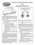
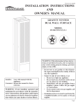
INSTALLATION INSTRUCTIONS
AND
OWNER’S MANUAL
FAN TYPE
VENTED
WALL FURNACE
MODEL
FAW-55IP
WARNING: If the information in these instructions are not followed exactly, a fire or explosion may result causing property damage,
personal injury or loss of life.
— Do not store or use gasoline or other flammable vapors and liquids in the vicinity of this or
any other appliance.
Installer: Leave this manual with the appliance.
Consumer: Retain this manual for future reference.
WARNING: If not installed, operated and maintained in accordance with the manufacturer’s
instructions, this product could expose you
to substances in fuel or from fuel combustion
which can cause death or serious illness.
— WHAT TO DO IF YOU SMELL GAS
• Do not try to light any appliance.
• Do not touch any electrical switch; do not
use any phone in your building.
• Immediately call your gas supplier from a
neighbor’s phone. Follow the gas supplier’s instructions.
• If you cannot reach your gas supplier, call
the fire department.
— Installation and service must be performed
by a qualified installer, service agency or the
gas supplier.
Page 1
TABLE OF CONTENTS
SECTION
PAGE
INTRODUCTION ..................................................................................................................3
SAFETY INFORMATION FOR USERS OF LP-GAS .........................................................4
INSTALLATION................................................................................................................ 5-9
LIGHTING INSTRUCTIONS .............................................................................................10
SERVICE AND MAINTENANCE SUGGESTIONS ................................................... 11-12
TROUBLESHOOTING .......................................................................................................13
S8600H TROUBLESHOOTING GUIDE...................................................................... 14-15
PARTS LIST .........................................................................................................................16
PARTS VIEW .......................................................................................................................17
VENTING ............................................................................................................................18
SERVICE NOTES ................................................................................................................19
Page 2
12429-10-0408
INTRODUCTION
Introduction
Always consult your local Building Department regarding
regulations, codes or ordinances which apply to the installation of
a vented wall furnace.
Instructions to Installer
1. Installer must leave instruction manual with owner after
installation.
2. Installer must have owner fill out and mail warranty card
supplied with furnace.
3. Installer should show owner how to start and operate furnace
and thermostat.
Warning:
Any change to this furnace or its control can be dangerous.
This is a heating appliance and any panel, door or guard
removed for servicing an appliance must be replaced prior
to operating the appliance.
General Information
This series is design certified in accordance with American National
Standard / CSA Standard Z21.86 and CSA 2.32 by the Canadian
Standards Association, as a Fan Type Vented Wall Furnace and
must be installed according to these instructions.
Notice: During initial firing of this unit, its paint will bake out and
smoke will occur. To prevent triggering of smoke alarms, ventilate
the room in which the unit is installed.
Installation on Rugs and Tile
If this appliance is installed directly on carpeting, tile or other
combustible material other than wood flooring the appliance shall
be installed on a metal or wood panel extending the full width and
depth of the appliance.
The base referred to above does not mean the fire-proof base as
used on wood stoves. The protection is for rugs that are extremely
thick and light colored tile.
Installation in Residential Garages
Gas utilization equipment in residential garages shall be installed
so that all burners and burner ignition devices are located not less
than 18” (457mm) above the floor.
Such equipment shall be located, or protected, so it is not subject
to physical damage by a moving vehicle.
Specifications
Model
BTU/HR (KW/H)
Height
Width
Depth
Gas Inlet
Vent Collar
CFM
Accessories
Any alteration of the original design, installed other than as
shown in these instructions or use with a type of gas not shown on
the rating plate is the responsibility of the person and company
making the change.
Important
All correspondence should refer to complete Model No., Serial
No. and type of gas.
FAW-55IP
55,000 (16.1)
82 3/8” (2092mm)
16” (406mm)
11 1/2” (292mm)
1/2” (13mm) Pipe
4” (102mm) Type B Oval
400
See Page 16
THIS IS A HEATING APPLIANCE
DO NOT OPERATE THIS APPLIANCE WITHOUT FRONT PANELS INSTALLED.
•
Due to high temperatures the appliance should be located
out of traffic and away from furniture and draperies.
•
Children and adults should be alerted to the hazards of
high surface temperatures and should stay away to avoid
burns or clothing ignition.
•
Young children should be carefully supervised when they
are in the same room as the appliance.
•
circulating air passageways of the appliance be kept
clean.
•
DO NOT put anything around the furnace that will
obstruct the flow of combustion and ventilation air.
•
DO keep the appliance area clear and free from combustible
material, gasoline and other flammable vapors and
liquids.
Clothing or other flammable material should not be placed
on or near the appliance.
•
DO examine venting system periodically and replace
damaged parts.
•
Any safety screen or guard removed for servicing an
appliance must be replaced prior to operating the
appliance.
•
DO make a periodic visual check of pilot and burners.
Clean and replace damaged parts.
•
Keep burner and control compartment clean.
•
CAUTION: Pilot hole cover must be kept tightly closed
during operation.
•
Installation and repair should be done by a QUALIFIED
SERVICE PERSON. The appliance should be inspected
before use and at least annually by a qualified service
person. More frequent cleaning may be required due to
excessive lint from carpeting, bedding materials, etc. It
is imperative that control compartments, burners and
•
DO NOT use this heater if any part has been under water.
Immediately call a qualified service technician to inspect
the heater and to replace any part of the control system
and any gas control which has been under water.
•
This furnace must not be connected to a chimney flue
serving a separate solid-fuel burning appliance.
12429-10-0408
Page 3
SAFETY INFORMATION FOR USERS OF LP-GAS
Propane (LP-Gas) is a flammable gas which can cause fires
and explosions. In its natural state, propane is odorless and
colorless. You may not know all the following safety precautions which can protect both you and your family from an
accident. Read them carefully now, then review them point
by point with the members of your household. Someday
when there may not be a minute to lose, everyone’s safety
will depend on knowing exactly what to do. If, after reading the following information, you feel you still need more
information, please contact your gas supplier.
LP-GAS WARNING ODOR
If a gas leak happens, you should be able to smell the gas because of the odorant put in the LP-Gas.
That’s your signal to go into immediate action!
•
Do not operate electric switches, light matches, use your
phone. Do not do anything that could ignite the gas.
•
Get everyone out of the building, vehicle, trailer, or area.
Do that IMMEDIATELY.
•
Close all gas tank or cylinder supply valves.
•
LP-Gas is heavier than air and may settle in low areas such
as basements. When you have reason to suspect a gas leak,
keep out of basements and other low areas. Stay out until
firefighters declare them to be safe.
•
Use your neighbor’s phone and call a trained LP-Gas service
person and the fire department. Even though you may not
continue to smell gas, do not turn on the gas again. Do not
re-enter the building, vehicle, trailer, or area.
•
Finally, let the service man and firefighters check for escaped
gas. Have them air out the area before you return. Properly
trained LP-Gas service people should repair the leak, then
check and relight the gas appliance for you.
NO ODOR DETECTED - ODOR FADE
Some people cannot smell well. Some people cannot smell the
odor of the chemical stench put into the gas. You must find out
if you can smell the odorant in propane. Smoking can decrease
your ability to smell. Being around an odor for a time can affect
your sensitivity or ability to detect that odor. Sometimes other
odors in the area mask the gas odor. People may not smell the
gas odor or their minds are on something else. Thinking about
smelling a gas odor can make it easier to smell.
The odorant in LP-gas is colorless, and it can fade under some
circumstances. For example, if there is an underground leak, the
movement of the gas through soil can filter the odorant. Odorants
in LP-Gas also are subject to oxidation. This fading can occur if
there is rust inside the storage tank or in iron gas pipes.
The odorant in escaped gas can adsorb or absorb onto or into walls,
masonry and other materials and fabrics in a room. That will take
some of the odorant out of the gas, reducing its odor intensity.
LP-Gas may stratify in a closed area, and the odor intensity could
vary at different levels. Since it is heavier than air, there may be
more odor at lower levels. Always be sensitive to the slightest
gas odor. If you detect any odor, treat it as a serious leak. Immediately go into action as instructed earlier.
SOME POINTS TO REMEMBER
•
•
•
•
Learn to recognize the odor of LP-gas. Your local LP-Gas
Dealer can give you a “Scratch and Sniff” pamphlet. Use it
to find out what the propane odor smells like. If you suspect
that your LP-Gas has a weak or abnormal odor, call your
LP-Gas Dealer.
If you are not qualified, do not light pilot lights, perform service,
or make adjustments to appliances on the LP-Gas system. If
you are qualified, consciously think about the odor of LP-Gas
prior to and while lighting pilot lights or performing service
or making adjustments.
Sometimes a basement or a closed-up house has a musty
smell that can cover up the LP-Gas odor. Do not try to light
pilot lights, perform service, or make adjustments in an area
where the conditions are such that you may not detect the
odor if there has been a leak of LP-Gas.
Odor fade, due to oxidation by rust or adsorption on walls
of new cylinders and tanks, is possible. Therefore, people
should be particularly alert and careful when new tanks or
cylinders are placed in service. Odor fade can occur in new
tanks, or reinstalled old tanks, if they are filled and allowed
Page 4
•
•
to set too long before refilling. Cylinders and tanks which
have been out of service for a time may develop internal rust
which will cause odor fade. If such conditions are suspected
to exist, a periodic sniff test of the gas is advisable. If you
have any question about the gas odor, call your LP-gas
dealer. A periodic sniff test of the LP-gas is a good safety
measure under any condition.
If, at any time, you do not smell the LP-Gas odorant and you
think you should, assume you have a leak. Then take the same
immediate action recommended above for the occasion when
you do detect the odorized LP-Gas.
If you experience a complete “gas out,” (the container is under no vapor pressure), turn the tank valve off immediately.
If the container valve is left on, the container may draw in
some air through openings such as pilot light orifices. If this
occurs, some new internal rusting could occur. If the valve is
left open, then treat the container as a new tank. Always be
sure your container is under vapor pressure by turning it off
at the container before it goes completely empty or having it
refilled before it is completely empty.
12429-10-0408
INSTALLATION
Ventilation and Combustion Air
Wall furnaces shall be installed in a location in which the facilities
for ventilation permit satisfactory combustion of gas and proper
venting under normal conditions. In buildings of conventional
frame, brick, or stone construction without tight storm windows
and doors, infiltration is normally adequate to provide air for
combustion and draft hood dilution.
Where appliances are installed in confined and unconfined spaces
within a building, the building being of unusually tight construction,
air for combustion and ventilation must be obtained directly from
outdoors or from such spaces that freely communicate with the
outdoors. Under these conditions, the confined and unconfined
spaces shall be provided with two permanent openings, one near
the top of the enclosure and one near the bottom; each opening
shall have a free area of not less than one square inch (6,45cm2)
per 2,000 BTU hr. (.6KW/H) of total input.
Qualified Installing Agency
Installation and replacement of gas piping, gas utilization equipment
or accessories and repair and servicing of equipment shall be
performed only by a qualified agency. The term “qualified agency”
means any individual, firm, corporation or company which either in
person or through a representative is engaged in and is responsible
for (a) the installation or replacement of gas piping or (b) the
connection, installation, repair or servicing of equipment, who is
experienced in such work, familiar with all precautions required
and has complied with all the requirements of the authority having
jurisdiction.
The installation must conform with local codes or, in the absence of
local codes, with the National Fuel Gas Code, ANSI Z223.1/NFPA
54,* Natural Gas and Propane Installation Code, CSA B149.1.
*Available from the American National Standards Institute, Inc., 11 West 42nd St.,
New York, N.Y. 10036.
Clearances
1. In selecting a location for installation, it is necessary to provide
adequate accessibility clearances for servicing and proper
installation.
2. The FAW-55 can be attached to the wall or recessed into the
wall up to 4 inches (102mm) in depth.
3. The wall in which the furnace is recessed has (0) zero (0mm)
clearance to the furnace sides and top.
4. When using side discharge registers, SOR-1 or SOK-1, the
furnace cannot be recessed into the wall.
5. Clearance to sidewall or combustible material is 4 inches
(102mm).
6. Ceiling clearance is 7 1/2 inches (191mm).
7. Floor and rear wall clearance is (0) zero inches (0mm).
8. Clearance of 18 inches (457mm) is required to adjacent wall or
combustible material when flush mounted SOR-1, side outlet
register is used.
Before Installing Consider The Following Venting
1. A chimney for residential-type or low-heat gas utilization
equipment shall extend at least 3 feet (914mm) above the
highest point where it passes through a roof of a building and
at least 2 feet (610mm) higher than any portion of building
within a horizontal distance of 10 feet (3m).
12429-10-0408
2.
3.
4.
This furnace must not be connected to a chimney flue serving
a separate solid-fuel burning appliance.
Uninsulated Single-Wall Metal Pipe shall not be used
outdoors in cold climates for venting gas utilization
equipment.
Attention! This Fan Type Vented Wall Furnace is equipped
with a vent safety switch. In the event of spillage of flue
products due to improper venting the vent safety switch will
open, which results in the main burners to “shut off”.
Refer to Figure 1 and page 16 for additional information regarding
U.L. Listed gas vent equipment.
Installing Optional Side Outlets
Side outlet register, SOR-1 may be installed on one or both sides
of the furnace at the required clearances of 18 inches (457mm) to
adjacent wall or combustible material as shown in Figure 2.
1.
2.
3.
4.
Locate and cut the 5 1/2” (140mm) square opening in the cabinet
side using the template from the kit, exposing the inner liner
knock-out.
Remove the knock-out.
Place the register on the 5 1/2” (140mm) opening with the
louvers set for the desired direction and mark the mounting
holes using the register as a template.
Drill (2) 1/8” (3mm) diameter holes in cabinet side and fasten the
register in place with (2) #10 x 1” (25mm) screws provided.
Side outlet kit, 10” (254mm) boot assembly with register, SOK-1
for warm air discharge into an adjoining room may be installed on
either side of the furnace at the required clearance of 4 inches to
adjacent wall as shown in Figure 3A.
1.
Locate and cut the 5 1/2” (140mm) square opening in the cabinet
side using the template from the kit, exposing the inner liner
knock-out.
2. Remove the knock-out.
3. Using the inner and outer boots as hole templates, mark and
drill (8) 1/8” (3mm) diameter holes in the inner liner and cabinet
side.
4. Using Figure 3A locate and cut a 6 3/4” (171mm) square
opening through walls.
5. Attach furnace to wall (see Attaching Furnace to Wall).
6. With furnace in place, after checking alignment of side outlet
opening in wall and furnace, place the 9 3/8” x 9 3/8” (238mm
x 238mm) side outlet wall plate over outer boot, pass the outer
boot through the wall and attach side outlet wall plate to furnace
side of wall with (2) #10 x 1” (25mm) screws provided.
7. Fasten outer boot to the cabinet side with (4) #8 x 1/4” (6mm)
screws provided.
8. Position and attach inner boot to inner liner with (4) #8 x 1/4”
(6mm) screws provided.
9. Locate the register with its louvers positioned for the desired
air discharge direction and mark the mounting holes using the
register as a template.
10. Drill (2) 1/8” (3mm) diameter holes in the wall and fasten the
register in place with (2) #10 x 1” (25mm) screws provided
Page 5
INSTALLATION
Installing Optional Rear Outlet
Rear outlet kit, 10” (254mm) boot assembly with register, ROK-1
for warm air discharge into an adjoining room.
7/1/2” (191mm) MINIMUM
CLEARANCE TOP TO
COMBUSTIBLES
Attention: Before furnace is attached to the wall, the wall opening
for the rear outlet must be cut, in addition to removal of the outer
and inner casing knockouts on furnace.
1.
2.
3.
4.
5.
6.
7.
8.
9.
The wall opening measurements for the rear outlet are the
following.
A. From floor to bottom of wall opening is 14 3/4”
(375mm).
B. From bottom of wall opening to top of wall opening is 8
1/2” (216mm) .
C. Wall opening width is 12 1/8” (308mm).
Remove outer casing knockout from outer casing back.
Remove inner casing knockout from inner casing.
Attach furnace to wall (see Attaching Furnace to Wall).
Align clearance holes on 8” x 12” (203mm x 305mm) boot with
screw holes on outer casing back and mark boot to be flush
with wall surface. Remove boot and cut to proper length.
Attach 8” x 12” (203mm x 305mm) boot to outer casing back
with (6) #10 x 1/2” (13mm) screws provided.
Align clearance holes on 6” x 10” (152mm x 254mm) duct with
screw holes on inner casing and mark duct to be 2 1/4” (57mm)
shorter than 8” x 12” (203mm x 305mm) boot. Remove duct
and cut to proper length.
Attach 6” x 10” (152mm x 254mm) duct to inner casing with
(6) #10 x 1/2” (13mm) screws provided.
Insert rear register into 8” x 12” (203mm x 305mm) boot.
Attach rear register to wall with (2) #10 x 1” (25mm) screws
provided.
4”(102mm) OVAL TYPE “B”
CONNECTION
VENT CENTER TO COMBUSTIBLES
MINIMUM CLEARANCE 9/16” (40mm)
VENT ENCLOSURE
DV-651 or DV-665 or
DV-666
SIDE OUTLET
KIT PART SOK-1
MINIMUM CLEARANCE
TO COMBUSTIBLES
18”(457mm)
Register
Part SOR-1
6 5/8 (168mm)
WALL TO VALVE INLET
4”(102mm) MINIMUM
CLEARANCE TO
COMBUSTIBLES
3”(76mm) TO CENTER OF
½”(13mm) INLET ELBOW
REAR OUTLET
REGISTER KIT #ROK-1
3 3/4”(95mm) FLOOR TO
CONTROL VALVE INLET
Figure 2
(102mm)
(102mm)
ALL CONNECTIONS MUST BE MECHANICALLY
MADE AND LISTED CLERANCES MAINTAINED
2 PIECE VENT ENCLOSURE
CUT TO THE PROPER LENGTH
*PARTS LISTED ARE TO BE PURCHASED
LOCALLY
SPACER STRAP*
BASE PLATE*
MOUNTING HOLE
BASE PLATE
GASKET
(102mm)
(140mm)
Figure 1
(140mm)
(406mm)
3 1/4” (83mm)
11 ½”(292mm)
Figure 3
Page 6
Figure 3A
12429-10-0408
INSTALLATION
Locating Furnace On Wall
The furnace is to be located on a wall. The furnace is 16 inches
(406mm) in width and normal 16 inches (406mm) on center studs
will not allow the furnace to be recessed into the wall unless a stud
is repositioned.
Compounds used on threaded joints of gas piping shall be resistant to
the action of liquefied petroleum gases. The gas lines must be checked
for leaks by the installer. This should be done with a soap solution
watching for bubbles on all exposed connections, and if unexposed, a
pressure test should be made.
A template is provided in furnace carton for locating gas line connection.
Also, refer to Figure 2 for positioning the furnace on wall and for
locating gas line connection.
Never use an exposed flame to check for leaks. Appliance must be
disconnected from piping at inlet of control valve and pipe capped
or plugged for pressure test. Never pressure test with appliance
connected; control valve will sustain damage!
Locating Gas Supply
The gas line can enter the furnace either through the floor or wall. The
gas line opening should be made at this time. Location of the opening
will be determined by the position of floor joists and the valve and
union used for servicing.
Locating Electric Supply
A 7/8” (22mm) diameter knockout is provided at the bottom of the
left and right side panels. A three-prong (grounding) plug assembly
is located within the control compartment (bottom) of the furnace.
Please remove 7/8” (22mm) knockout from appropriate side panel
when routing plug assembly to an electrical outlet.
Installation of Three-prong (Grounding) Plug Assembly
1. Disconnect nylon cap on 3’ (914mm) plug assembly from nylon
plug on wiring harness. Remove 3’ (914mm) plug assembly from
control compartment (bottom) of the furnace.
2. Remove 7/8” (22mm) knockout from appropriate side panel.
3. Insert nylon cap on 3’ (914mm) plug assembly into the 7/8” (22mm)
hole in the side panel.
4. Connect nylon cap on 3’ (914mm) plug assembly to nylon plug on
the wiring harness.
5. Place 7/8” (22mm) strain relief bushing around the cord of the 3’
(914mm) plug assembly. Insert 7/8” (22mm) strain relief bushing
into the 7/8” (22mm) hole in the side panel.
Attention! The 7/8” (22mm) strain relief bushing is located within
the same yellow envelope as the Installation Instructions and Owner’s
Manual.
Attaching Furnace to Wall
When attaching furnace to the wall remove that portion of baseboard
and molding on the wall which is behind the furnace. Attach furnace
to wall, at the outer casing top, with (2) toggle bolts provided and to
floor, at the outer casing bottom, with (2) #10 x 1 1/2” (38mm) screws
provided.
Attention! The screw holes on the outer casing bottom are off-set
above the floor approximately 3/8” (9.5mm). Do not over-tighten
screws and distort the off-set on the outer casing bottom. Distortion
of the outer casing bottom will not allow the lower front panel to be
attached to the furnace.
Gas Supply
Check all local codes for requirements, especially for the size and type
of gas supply line required. On Natural gas lines less than 15’ (4.5m)
long, use 1/2” (13mm) pipe; on longer runs, use 3/4” (19mm) iron
pipe or equal. On LP gas lines please consult LP gas supplier.
Installing a New Main Gas Cock
Each appliance should have its own manual gas cock.
A manual main gas cock should be located in the vicinity of the unit.
Where none exists, or where its size or location is not adequate, contact
your local authorized installer for installation or relocation.
12429-10-0408
A gas valve and ground joint union should be installed in the gas line
upstream of the gas control to aid in servicing. It is required by the
National Fuel Gas Code that a drip line be installed near the gas inlet.
This should consist of a vertical length of pipe tee connected into the
gas line that is capped on the bottom in which condensation and foreign
particles may collect.
(3mm)
(3mm)
Figure 4
Method of Installing a Tee Fitting Sediment Trap
The use of the following gas connectors is recommended:
— ANS Z21.24 Appliance Connectors of Corrugated Metal Tubing
and Fittings
— ANS Z21.45 Assembled Flexible Appliance Connectors of Other
Than All-Metal Construction
The above connectors may be used if acceptable by the authority
having jurisdiction.
Pressure Testing of the Gas Supply System
1. To check the inlet pressure to the gas valve, a 1/8” (3mm) N.P.T.
plugged tapping, accessible for test gauge connection, must be
placed immediately upstream of the gas supply connection to the
appliance.
2. The appliance and its individual shutoff valve must be disconnected
from the gas supply piping system during any pressure testing of
that system at test pressures in excess of 1/2 psig (3.5 kPa).
3. The appliance must be isolated from the gas supply piping system
by closing its individual manual shutoff valve during any pressure
testing of the gas supply piping system at test pressures equal to or
less than 1/2 psig (3.5 kPa).
Attention! If one of the above procedures results in pressures in
excess of 1/2 psig (14” w.c.) (3.5 kPa) on the appliance gas valve, it
will result in a hazardous condition.
Page 7
INSTALLATION
Checking Manifold Pressure
Both Propane and Natural gas valves have a built-in pressure regulator
in the gas valve. Natural gas models will have a manifold pressure
of approximately 3.5” w.c. (.871kPa) at the valve outlet with the inlet
pressure to the valve from a minimum of 5.0” w.c. (1.24kPa) for the
purpose of input adjustment to a maximum of 10.5” w.c. (2.615kPa)
Propane gas models will have a manifold pressure approximately 10.0”
w.c. (2.49kPa) at the valve outlet with the inlet pressure to the valve
from a minimum of 11.0” w.c. (2.739kPa) for the purpose of input
adjustment to a maximum of 13.0” w.c. (3.237kPa).
A 1/8” (3mm) N.P.T. plugged tapping, accessible for test gauge
connection, is located on the outlet side of the gas control.
The built-in regulator comes on at approximately 1/4th pressure and
full on in 10 seconds.
Figure 6
Electrode and pilot must be kept clean. Clean through pilot access
hole with a small brush (toothbrush) and water.
Proper Main Burner Flame
The correct flame will be a short blue inner flame with a much
larger light blue outer flame. The main burner (Figure 7) shows the
approximate height of each part of the flame for each gas. The burner
does not have a primary air adjustment. The flame will be correct if
the factory-set pressure and orifice opening are used. After the furnace
has been operating, the burner ports may be blocked by foreign matter
carried in by combustion air. Therefore, cleaning of the burner may
be needed for proper flame.
Figure 5
High Altitudes
For altitudes/elevations above 2,000 feet (610m), input ratings should
be reduced at the rate of 4 percent for each 1,000 feet (305m) above
sea level. Canadian High Altitudes for locations having an elevation
above mean sea level between 2,000 feet (610m) and 4,500 feet (1370m),
the manifold pressure is to be decreased from 3.5” w.c. (.871kPa) to
2.8” w.c. (.697kPa) for Natural Gas and from 10.0” w.c. (2.49kPa) to
8.0” w.c. (1.992kPa) for Propane Gas.
Proper Pilot Flame
The pilot flame (Figure 6) going to the spark must be large enough to
completely cover the sparking area. With the proper flame, only 2 or
3 sparks will occur. More sparks indicate a small pilot flame and no
ignition with spark stopping after approximately 90 seconds generally
means not enough flame.
To adjust pilot flame remove the pilot cover screw on the control valve
(Figure 5), and turn the adjustment screw clockwise to reduce flame.
Replace pilot cover screw to eliminate gas leakage.
The pilot flame will appear large. A blue nearly horizontal flame is
proper. The spark gap must be 1/8” (3mm) . A larger gap can result
in the spark occurring some other place. The pilot flame and the spark
gap are factory checked and tested.
After use, cleaning may be required for the proper flame.
Safety Lockout
S8600H module provides 100 percent shutoff, or safety lockout.
If the pilot fails to light within 90 seconds, the control system
will shut down. The control system must be reset by setting
the thermostat below room temperature for one minute or by
turning off power to the module for one minute.
Page 8
To clean burner port disconnect the gas supply to the valve, and remove
the eight screws fastening the burner door. After removing the burner
door from the combustion chamber, remove rear burner, pilot burner
and front burner. With front and rear burners removed from furnace,
force water into the ribbon ports and dry with air pressure.
4” (102mm) NAT
6” (152mm) LP
1 ½”(38mm) NAT
1/4” (6mm) LP
Figure 7
Replacing Fan and Oiling the Motor
The fan motor should be cleaned and oiled once each heating season.
To reach the motor, withdraw the metal shroud surrounding the fan
blade by removing the screws on each side. Oil holes are located on
the top at each end of the motor. Use a few drops of #10 motor oil.
To clean the motor, blow air through its ventilation openings with a
vacuum cleaner or low pressure air source.
If fan motor is replaced, the silicone rubber gaskets, see page 14, Index
No. 5, Part No. 712059 should also be replaced. The gaskets must be
stretched to fit the motor bolts into the gasket holes and then the motor
and gaskets installed on the motor mounting bars.
12429-10-0408
INSTALLATION
Wiring
The appliance, when installed, must be electrically grounded in
accordance with local codes or, in the absence of local codes, with
the National Electrical Code, ANSI/NFPA 70 or Canadian Electrical
Code, CSA C22.1, if an external electrical source is utilized. This
appliance is equipped with a three-prong [grounding] plug for your
protection against shock hazard and should be plugged directly
into a properly grounded three-prong receptacle. Do not cut or
remove the grounding prong from this plug. For an ungrounded
receptacle, an adapter, which has two prongs and a wire for grounding,
can be purchased, plugged into the ungrounded receptacle and its wire
connected to the receptacle mounting screw. With this wire completing
the ground, the appliance cord plug can be plugged into the adapter
and be electrically grounded. A 7/8” (22mm) hole is provided in the
junction box for use with a conduit connector if local codes require
this type of protection.
Thermostat Installation
The thermostat should be installed in the same room as the furnace 4’
(1.2m) to 5’ (1.5m) above the floor and away from another heat source
(cooking stove, hot water heater, etc.) including walls and doorways
with a heat source in an adjoining room. Do Not Install Thermostat
on Outside Wall.
Vent Safety Shutoff System
This appliance must be properly connected to a venting system. This
appliance is equipped with a vent safety shutoff system.
Warning: Operation of this wall furnace when not connected
to a properly installed and maintained venting system or
tampering with the vent safety shutoff system can result in
carbon monoxide (CO) poisoning and possible death.
This furnace is equipped with a manual reset vent safety switch. The
manual reset vent safety switch will cause gas flow to the main burners
to “shut off” due to improper venting or a blocked flue.
To reset the manual reset vent safety switch:
1. Remove upper front panel.
2. Depress red manual reset button. The manual reset vent safety
switch is located on the draft diverter.
3. Replace upper front panel.
If the manual reset vent safety switch continues to “shut off” the gas
flow to the main burners a qualified service person must be contacted
to inspect for improper venting, blockage in the vent pipe or the manual
reset vent safety switch for being defective.
Insulated Vent Enclosure
Vented wall furnaces installed in buildings with flat roofs can have
poor venting. The cold vent pipe will have a delay in proper venting
and cause the wall furnace to shut “OFF” by the vent safety switch.
To prevent delayed venting as well as condensation of flue products
an insulated vent enclosure is recommended.
Use type B vent pipe and maintain at least a one inch (25mm) clearance
to combustibles.
Use metal thimble to protect vent pipe as it passes through
combustibles.
(3m)
(.6m)
(3m)
More than 10”
Figure 8
12429-10-0408
Figure 9
Figure 10
Page 9
LIGHTING INSTRUCTIONS
FOR YOUR SAFETY READ BEFORE OPERATING
WARNING: If you do not follow these instructions exactly, a fire or explosion may result
causing property damage, personal injury or loss of life.
A. This appliance is equipped with an ignition device which
automatically lights the pilot.
Do not try to light the pilot by hand.
B. BEFORE OPERATING smell all around the appliance area for gas. Be sure to smell next to the floor
because some gas is heavier than air and will settle on
the floor.
WHAT TO DO IF YOU SMELL GAS
• Do not try to light any appliance.
• Do not touch any electrical switch;
Do not use any phone in your building.
• Immediately call your gas supplier from a neighbor’s
phone. Follow the gas supplier’s instructions.
• If you cannot reach your gas supplier, call the fire
department.
C. Use only your hand to push in or turn the gas control
knob. Never use tools. If the knob will not push in or
turn by hand, don’t try to repair it; call a qualified
service technician. Force or attempted repair may
result in a fire or explosion.
D. Do not use this appliance if any part has been under
water. Immediately call a qualified service technician
to inspect the appliance and to replace any part of
the control system and any gas control which has
been under water.
OPERATING INSTRUCTIONS
1. S T O P !
above.
Read the safety information
2. Set the thermostat to lowest setting.
3. Turn off all electric power to the appliance.
4. This appliance is equipped with an ignition
device which automatically lights the pilot. Do not try
to light the pilot by hand.
7. Wait ten (10) minutes
to clear out any gas.
Then smell for gas, including near the floor. If you smell
gas, STOP! Follow “B” in the safety information above.
If you don’t smell gas, go to the next step.
8. Tu r n g a s c o n t ro l k n o b c o u n t e rc l o c k w i s e
to “ON”.
9. Replace control access panel
panel).
(lower front
10. Turn on all electric power to the appliance.
11. Set thermostat to desired setting.
12. If the appliance will not operate, follow the instructions
“TO TURN OFF GAS TO APPLIANCE” and call your
service technician or gas supplier.
5. Remove control access panel (lower front panel).
6. Turn gas control knob clockwise
“OFF.”
to
TO TURN OFF GAS TO APPLIANCE
1. Set the thermostat to lowest setting.
2. Turn off all electric power to the appliance
if service is to be performed .
3. Remove control access panel (lower front
panel).
Page 10
4. Turn gas control knob clockwise
to “OFF.” Do not force.
5. Replace control
panel).
access panel
(lower front
12429-10-0408
SERVICE AND MAINTENANCE SUGGESTIONS
CALL SERVICEMAN
GENERAL: All furnaces have been fire-tested to check for proper
operation. This includes, main burner flame, pilot flame, fan operation,
fan control, limit control and automatic valve operation. If the furnace
fails to function on initial installation, it is advisable to re-check the
following:
1. 115 volts to the junction box.
2. Inlet gas pressure.
3. The 24 volt system.
4. Type of gas being used and that shown on the rating label.
STEP 1: Perform Visual Inspection.
A. With power off, make sure all wiring connections are clean and
tight.
B. Turn on power to appliance and ignition module.
C. Open manual shutoff valves in the gas line to the appliance.
D. Do gas leak test ahead of gas control if piping has been
disturbed.
GAS LEAK TEST: Paint pipe joints with rich soap and water
solution. Bubbles indicate gas leak. Tighten joints to stop leak.
The Service Department at Empire Comfort Systems, Inc. may be
contacted to assist in servicing furnace.
STEP 2: Review Normal Operating Sequence and Module
Specifications.
Servicing the Pilot and Main Burners, Pilot Orifice, and Main
Burner Orifices: Disconnect the gas supply at the inlet to the control
valve. Then remove the burner door to which the above components
are attached.
STEP 3: Reset the Module.
A. Turn the thermostat to its lowest setting.
B. Wait one minute.
As you do Steps 4 and 5, watch for points where operation
deviates from normal. Refer to Troubleshooting Chart to correct
problem.
Servicing The Fan Motor: The upper front panel, the shroud
surrounding the fan blade and fan blade must be removed. See “Oiling
the Motor” paragraph on page 7.
S8600H INTERMITTENT IGNITION MODULE
SPECIFICATIONS
Lockout timing is 90 seconds. Ignition timing is until pilot lights or
lockout occurs.
Module shuts down and cuts power to gas control on flame failure.
Gas control closes to provide 100 percent lockout on flame failure.
Manual reset required.
ELECTRICAL RATINGS:
Voltage and frequency: 20.5 to 28.5V (24V nom.) 60 Hz.
Current rating: 0.2 A.
Valve contact ratings (at 24 Vac):
Run
Inrush
Pilot 1.0 A
10.0 A
Main 1.0 A
10.0 A
SPARK GENERATOR OUTPUT: 13kV peak at 25 pf load.
THERMOSTAT ANTICIPATOR SETTING: 0.2 A plus pilot valve
rating plus main valve rating.
THERMOSTAT COMPATIBILITY: Standard models compatible with
all open-close switch type 24 Vac thermostats capable of supplying
rated voltage and current to the module.
AMBIENT TEMPERATURE RATING: Minus 40 F to plus 175 F
(minus 40 C to plus 79 C).
RELATIVE HUMIDITY RATING: 5 to 90 percent RH at 95 F.
FLAME FAILURE RESPONSE TIME: 0.8 seconds at 1.0 uA flame
current.
FLAME CURRENT: 1 uA, min.
CHECKOUT
Check out the gas control system:
1. At initial installation of the appliance.
2. As part of regular maintenance procedures.
3. As the first step in troubleshooting.
4. Any time work is done on the system.
12429-10-0408
STEP 4: Check Safety Lockout Operation.
A. Turn gas supply off.
B. Set thermostat above room temperature to call for heat.
C. Watch for spark at pilot burner.
D. Time length of spark operation. Maximum spark time is 90
seconds.
E. Open manual gas cock and make sure no gas is flowing to pilot
or main burner.
F. Set thermostat below room temperature and wait one minute
before continuing.
STEP 5: Check Normal Operation.
A. Set thermostat above room temperature to call for heat.
B. Make sure pilot lights smoothly when gas reaches the pilot
burner.
C. Make sure main burner lights smoothly without flashback. Make
sure burner operates smoothly without floating or lifting.
D. If gas line has been disturbed, complete gas leak test.
GAS LEAK TEST: Paint gas control gasket edges and all pipe
connections downstream of gas control, including pilot tubing
connections, with rich soap and water solution. Bubbles indicate
gas leaks. Tighten joints and screws or replace component to stop
gas leak.
E. Turn thermostat below room temperature. Make sure main burner
and pilot flames go out.
OPERATION
Module operation can be conveniently divided into two phases
for S8600H. The phases are trial for ignition and main burner
operation.
TRIAL FOR IGNITION
Pilot Ignition
Following call for heat (system start on S8600H), the module energizes
the first main valve operator. The first main valve opens, which allows
gas to flow to the pilot burner. At the same time, the electronic spark
generator in the module produces a 13,000 volt spark pulse output (at
25 pf load). The voltage generates a spark at the igniter-sensor that
lights the pilot.
Page 11
SERVICE AND MAINTENANCE SUGGESTIONS
If the pilot does not light, or the pilot flame current is not at least
1.0 uA and steady, the module will not energize the second main
valve and the main burner will not light.
Safety Lockout
S8600H provides 100 percent shutoff, or safety lockout. A timer
starts timing the moment the trial for ignition starts. Ignition spark
continues only until the timed trial for ignition period ends. Then
the module goes into safety lockout. Lockout de-energizes the
first main valve operator and closes the first main valve in the gas
control, stopping pilot gas flow. The control system must be reset
by setting the thermostat below room temperature for one minute
or by turning off power to the module for one minute.
Main Burner Operation
When the pilot flame is established, a flame rectification circuit
is completed between the sensor and burner ground. The flame
sensing circuit in the module detects the flame current, shuts off the
spark generator and energizes the second main valve operator. The
second main valve opens and gas flows to the main burner, where
it is ignited by the pilot burner. The flame current also holds the
safety lockout timer in the reset (normal) operating condition.
When the call for heat ends, both main valve operators are deenergized, and both main valves in the gas control close.
CAUTION: Label all wires prior to disconnection when
servicing controls. Wiring errors can cause improper and
dangerous operation. Verify proper operation after servicing.
S8600H NORMAL OPERATING SEQUENCE
START
Thermostat, Wall Switch,
Remote, Etc. Calls for Heat
STAGE 1
Trial for Ignition
POWER INTERRUPTION
System shuts off. Restarts when
power is restored.
PILOT FLAME FAILURE
Second main operator closes.
Module starts trial for ignition.
Spark Generator Powered
First Valve (Pilot)
Operator Opens
PILOT BURNER OPERATION
Pilot burner lights.
Pilot burner does not light
Module senses flame current.
OR
MODULE
RESPONSE
S8600H
After 90 seconds*pilot valve
closes, spark stops.
* Lockout timing is stamped on module.
STAGE 2
Main Burner
Operation
IF FLAME CURRENT SENSED
Spark generator off
Second valve operator
(Main) opens.
MAIN BURNER OPERATION
Module monitors pilot
flame current.
END
Page 12
THERMOSTAT SATISFIED
Valves close. Pilot and
main burners are off.
12429-10-0408
TROUBLESHOOTING
Important
1. The following service procedures are provided as a general
guide.
2. Meter readings between gas control and ignition module must
be taken within the trial for ignition period. Once the ignition
module locks out, the system must be reset by setting the
thermostat down for at least one minute before continuing.
3. If any component does not function properly, make sure it is
correctly installed and wired before replacing it.
4. The ignition module cannot be repaired. If it malfunctions, it
must be replaced.
5. Only trained, experienced service technicians should service
intermittent pilot systems.
Perform the CHECKOUT steps on page 10 as the first step in
troubleshooting. Then check TROUBLESHOOTING GUIDE
to pinpoint the cause of the problem. If troubleshooting indicates
an ignition problem, see Ignition System Checks below to isolate
and correct the problem.
Following troubleshooting, perform the CHECKOUT procedure
(page 10 ) again to be sure system is operating normally.
Ignition System Checks
Step 1: Check ignition cable.
Make sure:
A. Ignition cable does not touch any metal surfaces.
B. Ignition cable is no more than 36 inches (914mm) long.
C. Connections to the ignition module and to the igniter-sensor
are clean and tight.
D. Ignition cable provides good electrical continuity.
Step 2: Check ignition system grounding.
Nuisance shutdowns are often caused by a poor or erratic
ground.
A. A common ground, usually supplied by the pilot burner
bracket, is required for the module and the pilot burner/igniter
sensor.
• Check for good metal-to-metal contact between the pilot
burner bracket and the main burner.
• Check the ground lead from GND (BURNER) terminal on
the module to the pilot burner. Make sure connections are
clean and tight. If the wire is damaged or deteriorated, replace
it with No. 14-18 gauge, moisture-resistant, thermoplastic
insulated wire with 105 C (221 F) minimum rating.
• If flame rod or bracket are bent out of position, restore to
correct position.
• Replace pilot burner/igniter sensor if insulator is
cracked.
Step 3: Check spark ignition circuit. You will need a short jumper
wire made from ignition cable or other heavily insulated
wire.
A. Close the manual gas valve.
B. Disconnect the ignition cable at the SPARK terminal on the
module.
12429-10-0408
WARNING
When performing the following steps, do not touch stripped
end of jumper or SPARK terminal. The ignition circuit
generates 13,000 volts at 25 pf load and electrical shock
can result.
C.Energize the module and immediately touch one end of the jumper
firmly to the GND terminal on the module. Move the free end
of the jumper slowly toward the SPARK terminal until a spark
is established.
D. Pull the jumper slowly away from the terminal and note the
length of the gap when sparking stops. Check table below.
ARC LENGTH
ACTION
No arc or arc less than Check external fuse, if provided.
1/8 inch (3mm).
Verify power at module input terminal.
Replace module if fuse and power
okay.
Arc 1/8 inch (3mm)
Voltage output is okay.
or longer.
Step 4: Check pilot flame current.
A. Turn off furnace at thermostat.
B. Disconnect main valve wire from the TH or MV terminal on
the gas control.
C. Disconnect ground wire from GND (BURNER) terminal at
module.
D. Connect a meter (dc microamp scale) in series with the ground
lead.
• Disconnect ground lead from GND terminal on ignition
module.
• Connect the black (negative) meter lead to the ignition
module GND (BURNER) terminal.
• Connect the red (positive) meter lead to the free end of the
ground lead.
E. Set thermostat to call for heat. The spark will light the pilot but
the main burner will not light because the main valve actuator
is disconnected.
F. Read the meter. The flame sensor current must be steady and
at least 1.0 uA.
G. If the reading is less than the minimum or unsteady,
• Make sure pilot flame envelopes 3/8 (9.5mm)to 1/2 inch
(13mm) of the flame rod.
• If necessary, adjust pilot flame by turning the pilot
adjustment screw on the gas control clockwise to decrease
or counterclockwise to increase pilot flame. Following
adjustment, always replace pilot adjustment cover screw
and tighten firmly to assure proper gas control operation.
• Check for cracked ceramic insulator, which can cause short
to ground, and replace igniter-sensor if necessary.
• Make sure electrical connections are clean and tight. Replace
damaged wire with moisture-resistant No. 18 wire rated for
continuous duty up to 105 C (221 F).
H. Remove meter and reconnect all wires. Return system to
normal operation before leaving job.
Page 13
S8600H TROUBLESHOOTING GUIDE
Page 14
12429-10-0408
S8600H TROUBLESHOOTING GUIDE
Green LED Status Codes
Green LED
Flash Code
(X + Y)a
Indicates
Next System Action
Recommended Service Action
OFF
No “Call for Heat”
Not applicable
None
Flash Fast
Startup-Flame sense calibration
Not applicable
None
Heart Beat
Normal operation
Not applicable
None
3
Recycle
- Flame failed during run
Initiate new trial for ignition. Flash code If system fails to light on next trial for
will remain through the ignition trial ignition, check gas supply, pilot burner,
until flame is proved.
flame sense wiring, contamination of
flame rod, burner ground connection.
4
Flame sensed out of sequence
If situation self corrects within 10 seconds, control returns to normal sequence.
If flame out of sequence remains longer
than 10 seconds, control goes to Flash
code 6 + 4 (see below).
7
Flame sense leakage to ground
Control remains in wait mode. When Check flame sense lead wire for damage
the fault corrects, control resumes nor- or shorting. Check that flame rod is in
mal operation after a one minute delay. proper position.
Check flame rod ceramic for cracks,
damage or tracking.
8
Low secondary voltage supply - Control remains in wait mode. When Check transformer and AC line for proper
below 15.5 Vac)
the fault corrects, control resumes nor- input voltage to the control. Check with
mal operation after a one minute delay. full system load on the transformer.
6+2
Failed trial for ignition resulting Remain in lockout until “Call for Heat” Check gas supply, pilot burner, spark
in lockout
is cycled.
and flame sense wiring, flame rod contaminated or out of position, burner
ground connection.
6+3
More than 5 flame failures during Remain in lockout until “Call for Heat” Check gas supply, pilot burner, flame
run on the same “Call for Heat” is cycled.
sense wiring, contamination of flame
resulting in lockout
rod, burner ground connection.
6+4
Flame sensed out of sequence - Control waits until flame is no longer
longer than 10 seconds
sensed and then goes to soft lockout.
Flash code continues. Control auto resets from soft lockout after one hour.
ON
Soft lockout due to error detected Control auto resets from soft lockout af- Reset by cycling “Call for Heat.” If erduring self check sequences
ter one hour.
ror repeats, replace the control.
Check for pilot flame. Replace gas valve
if pilot flame present. If no pilot flame,
cycle “Call for Heat.” If error repeats,
replace control.
Check for pilot flame. Replace gas valve
if pilot flame present. If no pilot flame,
cycle “Call for Heat.” If error repeats,
replace control.
Flash Code Descriptions:
- Flash Fast: Rapid blinking
- Heartbeat: Constant 1/2 second bright 1/2 second dim cycles
- A single flash code number signifies that the LED flashes X times at 2Hz, remains off for two seconds,
and then repeats the sequence.
- X + Y flash codes signify that the LED flashes X times at 2Hz, remains off for two seconds, flashes Y
times at 2Hz, remains off for three seconds, and then repeats the sequence.
a
12429-10-0408
Page 15
PARTS LIST
PLEASE NOTE: When ordering parts, it is very important that part number and description of part coincide.
Index
No.
Part
Number
1
2
3
4
5
6
7
8
9
10
11
12
13
14
15
16
17
18
19
20
21
22
23
23
24
25
25
26
27
WFA-115
11763
632024
11764
712059
R-619
11787
DV-635
11766
11759
DV-627
R-1619
DV-823
R-1749
R-1587
8720130
11765
DV-832
912073
R-1941
DV-826
732062
762217
762113
DV-808
DV-562
15667
DV-824
P-88-42
27
742223
28
29
30
DV-687
712045
DV-064
Description
Baseplate Gasket
Outer Casing Top
Motor Mount (Four Required)
Motor Mounting Bar (Two Required)
Gasket (Two Required)
Motor
Fan Blade
Combustion Chamber
Fan Housing
Side Panel
Upper Front Panel
Bushing
Diverter Assembly
Vent Safety Switch
Vent Safety Wire Assembly
Bushing
Switch Compartment Assembly
Switch Compartment Cover
Limit Control
Fan Control
Rear Burner
Spark Plug Wire
Pilot Burner With Orifice LP Gas
Pilot Burner With Orifice Natural Gas
Pilot Tubing
Lower Front Panel (USA)
Lower Front Panel (Canada)
Front Burner
Main Burner Orifice Natural Gas
(Two Required)
Main Burner Orifice LP Gas
(Two Required)
Manifold and Plate Assembly
Manifold Gasket
Cover Plate For Observation Hole
Index
No.
Part
Number
31
31
32
33
34
35
DV-847
DV-972
DV-691-A
712059
722040
R-2147
35
R-2149
36
37
38
39
39
40
41
42
43
44
UH-810
R-1995
UH-451
11761
15670
8720148
872053
872087
DV-671
DV-765
45
DV-764
46
47
48
49
50
51
52
Not Shown
Not Shown
Not Shown
Not Shown
Not Shown
Not Shown
872050
R-1616
DV-692
8720140
DV-684
DV-629
11759
R-9832
R-9833
R-6389
862060
742245
7421110
Description
Burner Door Natural Gas
Burner Door LP Gas
Seal Bracket
Gasket Tubing Seal
Manifold Union
Gas Valve VR8204C 1126 LP Gas
(10.0”)
Gas Valve VR8204C 1001 Natural Gas
(3.5”)
Transformer Mounting Bracket
Transformer
Junction Box Cover
Outer Casing Bottom (USA)
Outer Casing Bottom (Canada)
Bushing
Cord Set
Bushing
Manifold Support
Gasket for Chamber Air Inlet
(Top & Bottom) (Two Required)
Gasket for Chamber Air Inlet
(Sides) (Two Required)
Wire Harness
Control Module
Control Module Mounting Bracket
Bushing
Inner Lining Assembly
Casing Back
Side Panel
Wiring Assembly Upper
Wiring Assembly Lower
24 Volt Wall Thermostat
Lighter Rod
Pilot Orifice LP
Pilot Orifice Natural
USE ONLY MANUFACTURER’S REPLACEMENT PARTS. USE OF ANY OTHER PARTS COULD CAUSE INJURY OR DEATH.
How To Order Repair Parts.
Parts can be ordered only through your service person or dealer. For best results, the service person or dealer should order parts
through the distributor. Parts can be shipped directly to the service person/dealer.
All parts listed in the Parts List have a Part Number. When ordering parts, first obtain the Model Number from the name plate on your
equipment. Then determine the Part Number (not the Index Number) and the Description of each part from the following appropriate
illustration and list. Be sure to give all this information.
Furnance Model Number
Part Description
Furnance Serial Number
Part Number
Do not order bolts, screws, washers or nuts. They are standard hardware items and can be purchased at any local hardware store.
Shipments contingent upon strikes, fires and all causes beyond our control.
Page 16
12429-10-0408
PARTS VIEW
Empire Comfort Systems, Inc. Nine Eighteen Freeburg Ave.
12429-10-0408
Belleville, Illinois 62222-0529
Page 17
VENTING
Model No. FAW-55 may be vented as shown. The vent cap must
be at least 12 feet (3.7m) above the floor. Clearance to combustible
construction is held by the fixed spacers at 1 inch (25mm) with B-1
vent pipe. Installation must conform to local codes.
4” (102mm) Round (all parts purchase locally except item 2)
1. Type B-1 round pipe
2. Part No. DV-648, 4” (102mm) oval-to-round flue adapter
kit (see accessories)
3. Single story type B-1 gas vents require a baseplate and one
pair of ceiling plate spacers.
4. Multi-story type B-1 gas vents require a baseplate, one pair
of ceiling plate spacers at the first floor ceiling and one pair
of fire stop spacers at each successive ceiling level.
Use U.L. listed gas vent equipment when installing the FAW-55.
For vent pipe running through walls, roof, and within one inch
(25mm) of combustible construction, use B-1 (one inch (25mm)
clearance to combustibles) vent pipe. Type B-2 x 4 or Type B-2 x
6 are to be used in conjunction with a Listed fire stop spacer.
Type BW gas vent pipe is available for single story or multi-story
installations. Type BW gas vent pipe is to be used with the Listed
base plate, ceiling plate spacers and fire stop spacers.
4” (102mm) Oval (all parts purchase locally)
1. Type B-1 oval pipe
2. Single story type B-1 gas vents require a baseplate and one
pair of ceiling plate spacers.
3. Multi-story type B-1 gas vents require a baseplate, one pair
of ceiling plate spacers at the first floor ceiling and one pair
of fire stop spacers at each successive ceiling level.
4” (102mm) Oval In-The-Wall (all parts purchase locally)
1. Type B-1 oval pipe
2. Type B-1 oval elbows
3. Single story type B-1 gas vents require a baseplate and one
pair of ceiling plate spacers.
4. Multi-story type B-1 gas vents require a baseplate, one pair
of ceiling plate spacers at the first floor ceiling and one pair
of fire stop spacers at each successive ceiling level.
VENT
ENCLOSURE
(not shown)
ADAPTER
SIDE
FRONT
Stud space around gas vents must be free of obstructions and
building paper.
BRACKET
Accessories
Part No.
Description
SOR-1
Register, side outlet, fixed register
SOK-1
Side outlet, 10” (254mm) maximum extension,
fixed register
ROK-1
Rear Outlet, 10” (254mm) maximum extension,
adjustable register
DV-651 Vent enclosure, 14” (356mm) [for room up to 96
1/2” (245cm) in height]
DV-665 Vent enclosure, 24” (610mm) [for rooms up to
106 1/2” (270.5cm) in height]
DV-666 Vent enclosure, 36” (914mm) [for rooms up to
118 1/2” (301cm) in height]
DV-648 4” (102mm) Oval-to-Round flue adapter kit
BASEPLATE
SIDE
SPACER
o
48 ELBOWS
4” (102MM) OVAL STD.
BASEPLATE
SIDE
Page 18
FRONT
FRONT
12429-10-0408
SERVICE NOTES
12429-10-0408
Page 19
EMPIRE
Comfort Systems
Empire Comfort Systems Inc.
918 Freeburg Ave. Belleville, IL 62220
If you have a general question about our products, please e-mail us at
[email protected].
If you have a service or repair question, please contact your dealer.
www.empirecomfort.com
Page 20
12429-10-0408