1
Y690A Series
Instruction Manual
Form 5463
February 2009
Y690A Series Pressure Reducing Regulators
!
Warning
Fisher® regulators must be installed,
operated, and maintained in accordance
with federal, state, and local codes, rules
and regulations, and Fisher instructions.
If the regulator vents gas or a leak
develops in the system, service to the unit
may be required. Failure to correct trouble
could result in a hazardous condition.
Call a gas service person to service
the unit. Only a qualified person must
install or service the regulator.
W7293
Figure 1. Types Y690A and Y690AH Direct-Operated Pressure
Reducing Regulators
Introduction
Scope of Manual
This Instruction Manual provides instruction for
installation, startup, maintenance, and parts list for
the Y690A Series pressure reducing regulators.
Instructions and parts lists for other equipment used
with these regulators are found in separate manuals.
Description
Specifications
The Specifications section on page 2 provides the
ratings and other specifications for the Y690A Series.
The following information is stamped on the regulator
at the factory: type number, date of manufacture,
spring range, orifice size, maximum inlet pressure,
maximum operating outlet pressure, and outlet
pressure which may damage regulator parts.
D102587X012
The Y690A Series self-contained, spring-loaded
regulators (Figure 1) provide economical pressure
reducing control in a variety of commercial and
industrial applications. The Y690A Series pressure
reducing regulator (Figure 1) is ideally suited to
control gas supply to in-plant processing equipment.
The rugged casings and sliding pusher post design
withstands the full 150 psig (10,3 bar) inlet pressure
at both the inlet and outlet connections. Because
these regulators can withstand the full inlet pressure,
a downstream relief valve is not required to protect
the downstream side of the regulator unless full
capacity relief is required. Available type numbers are
described in the Specifications section.
www.emersonprocess.com/regulators
Y690A Series
Specifications
Maximum Emergency Outlet Pressure to Avoid
Internal Parts Damage(1)
150 psig (10,3 bar)
Available Configurations
Type Y690A—Low-pressure, 1 to 7-inches w.c.
(2 to 17 mbar), direct-operated regulator with internal registration requiring no downstream control line.
Outlet Pressure Ranges(1)
See Table 2
Type Y690AH—High-pressure, 5-inches w.c. to
7 psig (12 mbar to 0,48 bar), direct-operated regulator with internal registration requiring no downstream control line.
Orifice Sizes and Flow Sizing Coefficients
See Table 4
Regulator Temperature Capabilities(1)
With Nitrile (NBR):
-20° to 180°F (-29° to 82°C) With Fluorocarbon (FKM):
40° to 300°F (4° to 149°C)
With Ethylenepropylene (EPDM):
-20° to 275°F (-29° to 135°C)
With Perfluoroelastomer (FFKM):
-20° to 300°F (-29° to 149°C)
Type Y690AM—Low-pressure, 1 to 7-inches w.c.
(2 to 17 mbar), direct-operated regulator. The
Type Y690AM has a blocked throat and O-ring stem seal for use when external registration is required. Lower diaphragm casing assembly is tapped for 1/2 NPT for control line connection.
Type Y690AHM—High-pressure, 5-inches w.c. to
7 psig (12 mbar to 0,48 bar), direct-operated regulator with a blocked throat and O-ring stem seal for use when external registration is required. Lower diaphragm casing assembly is tapped for 1/2 NPT for control line connection.
Pressure Registrations
Types Y690A and Y690AH: Internal
Types Y690AM and Y690AHM: External
Body Sizes and End Connection Styles
See Table 1
Spring Case Connection
1/4 NPT
Maximum Allowable Inlet Pressure(1)
150 psig (10,3 bar)
Diaphragm Case Connection
1/2 NPT
Maximum Operating Inlet Pressure(1)
See Table 3
Approximate Weight
19 pounds (9 kg)
Maximum Outlet (Casing) Pressure(1)
150 psig (10,3 bar)
1. The pressure/temperature limits in this Instruction Manual and any applicable standard or code limitation should not be exceeded.
Table 1. Body Sizes and End Connection Styles
body material(1)
body size, nps (dn)
3/4 or 1 (20 or 25)
Ductile Iron
Stainless Steel
npt
npt, cl150 rf, cl300 rf, or pn 16/25/40
1. All flanges are welded.
Table 2. Outlet Pressure Ranges
TYPEs
Y690A and Y690AM
Y690AH and
Y690AHM
Outlet Pressure Ranges
1 to 2.5-inches w.c. (2 to 6 mbar)
2.5 to 7-inches w.c. (6 to 17 mbar)
5 to 10-inches w.c. (12 to 25 mbar)
7 to 16-inches w.c. (17 to 40 mbar)
15-inches w.c. to 1.2 psig (37 mbar to 0,08 bar)
1.2 to 2.5 psig (0,08 to 0,17 bar)
2.5 to 4.5 psig (0,17 to 0,31 bar)
4.5 to 7 psig (0,31 to 0,48 bar)
Spring PART
NUMBER
Spring
COLOR
Spring Wire
Diameter,
inches (mm)
1B558527052(1)(2)
1B653827052(1)
Orange
Red
0.072 (1,83)
0.085 (2,16)
3.78 (96,0)
3.62 (92,0)
1B653827052
1B653927022
1B537027052
Red
Unpainted
Yellow
0.085 (2,16)
0.105 (2,67)
0.114 (2,90)
3.62 (92,0)
3.75 (95,2 )
4.31 (109)
1B537127022
1B537227022
1B537327052
Light green
Light blue
Black
0.156 (3,96)
0.187 (4,75)
0.218 (5,54)
4.06 (103)
3.94 (100)
3.98 (101)
1. To achieve the published outlet pressure range the spring case must be installed pointing down.
2. Do not use Fluorocarbon (FKM) diaphragm with this spring at diaphragm temperatures lower than 60°F (16°C).
2
spring free
length,
inches (mm)
Y690A Series
valve disk
lever
pitot tube for
types Y690A
and Y690AH
valve stem
SLIDING PUSHER POST
B2625
INLET PRESSURE
OUTLET PRESSURE
overpressure spring
ATMOSPHERIC PRESSURE
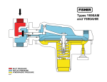
Figure 2. Y690A Series Operational Schematic
Principle of Operation
stem the valve disk moves closer to the orifice and
reduces gas flow. If demand downstream increases,
pressure under the diaphragm decreases. Spring
force pushes the pusher post assembly downward, the
valve disk moves away from the orifice, and the gas
flow increases.
Refer to Figure 2. When downstream demand
decreases, the pressure under the diaphragm
increases. This pressure overcomes the regulator
setting (which is set by a spring). Through the action
of the sliding pusher post assembly, lever, and valve
Table 3. Maximum Operating Inlet Pressures
Outlet Pressure Range, PSIG (bar)
Types Y690A and Y690AM
ORIFICE
SIZE,
1 to
INCHES (mm) 2.5-Inches w.c.
(2 to 6 mbar)
2.5 to
7-Inches w.c.
(6 to 17 mbar)
Types Y690AH and Y690AHM
5 to
7 to
10-Inches w.c. 16-Inches w.c.
(12 to 25 mbar) (17 to 40 mbar)
15-inches w.c.
to 1.2 Psig
(37 mbar to
0,08 bar)
1.2 to 2.5 Psig
(0,08 to
0,17 bar)
2.5 to 4.5 Psig
(0,17 to
0,31 bar)
4.5 to 7 Psig
(0,31 to
0,48 bar)
1/8 (3,2)
150 (10,3)
150 (10,3)
150 (10,3)
150 (10,3)
150 (10,3)
150 (10,3)
150 (10,3)
150 (10,3)
1/4 (6,4)
3/8 (9,5)
40 (2,8)
20 (1,4)
60 (4,1)
20 (1,4)
75 (5,2)
35 (2,4)
75 (5,2)
35 (2,4)
75 (5,2)
35 (2,4)
150 (10,3)
60 (4,1)
150 (10,3)
60 (4,1)
150 (10,3)
60 (4,1)
10 (0,69)
5 (0,34)
10 (0,69)
5 (0,34)
10 (0,69)
6 (0,41)
12 (0,83)
8 (0,55)
12 (0,83)
8 (0,55)
1/2 (13)
9/16 (14)
8 (0,55)
5 (0,34)
8 (0,55)
5 (0,34)
8 (0,55)
5 (0,34)
Table 4. Flow and Sizing Coefficients
ORIFICE SIZE,
INCHES (mm)
1/8
1/4
3/8
1/2
9/16
(3,2)
(6,4)
(9,5)
(13)
(14)
WIDE-OPEN COEFFICIENTS
(FOR RELIEF VALVE SIZING)
Cv
Cg
0.35
1.43
3.14
5.71
7.14
12.3
50
110
200
250
C1
Km
35
0.79
IEC SIZING COEFFICIENTS
XT
FD
FL
0.78
0.50
0.89
3
Y690A Series
HORIZONTAL PIPELINE
VENT POINTED DOWN
HORIZONTAL PIPELINE
VENT POINTED DOWN
DOWNSTREAM CONTROL LINE
TYPE Y690AH
B2626
TYPE Y690AHM
INLET PRESSURE
OUTLET PRESSURE
ATMOSPHERIC PRESSURE
DOWNSTREAM CONTROL PRESSURE
Figure 3. Types Y690AH and Y690AHM Actuator Casing Drainage Schematics
Installation
Note
!
Warning
Personal injury, property damage,
equipment damage, or leakage due to
escaping gas or bursting of pressurecontaining parts may result if this
regulator is overpressured or installed
where service conditions could exceed
the limits given in the Specifications
section (page 2), or where conditions
exceed any ratings of the adjacent
piping or piping connections. To
avoid such injury or damage, provide
pressure-relieving or pressure-limiting
devices (as required by the appropriate
code, regulation, or standard) to
prevent service conditions from
exceeding those limits.
Additionally, physical damage to the
regulator could cause personal injury
or property damage due to escaping
gas. To avoid such injury or damage,
install the regulator in a safe and well
ventilated location.
Regulator operation within ratings does not preclude
the possibility of damage from debris in the lines
or from external sources. A regulator should be
inspected for damage periodically and after any
overpressure condition beyond the emergency outlet
pressure limit specified in the Specifications section
(page 2). Key numbers referenced in this section are
shown in Figures 5, 6, and 7.
4
If the regulator is shipped mounted on
another unit, install that unit according
to the appropriate instruction manual.
1. Only personnel qualified through training and experience should install, operate, and maintain a regulator. For a regulator that is shipped
separately, make sure there is no damage to, or foreign material in the regulator. Also ensure that all tubing and piping are free of debris.
2. The regulator may be installed in any position
as long as the flow through the body is in the direction indicated by the arrow on the body. Normal installation is with the spring case
barrel vertical above or below the diaphragm case. However, when using a Type Y690A or
Y690AM regulator, for proper operation to achieve the published capacities, the spring case barrel should be installed pointed down as shown in
Figure 1. For complete actuator drainage of
Types Y690AH and Y690AHM, the regulator should be installed as shown in Figure 3. If continuous operation of the system is required during inspection or maintenance, install a three-
valve bypass around the regulator.
!
Warning
A regulator may vent some gas to
the atmosphere. In hazardous or
flammable gas service, vented gas may
accumulate and cause personal injury,
death, or property damage due to fire or
explosion. Vent a regulator in hazardous
gas service to a remote, safe location
Y690A Series
away from air intakes or any hazardous
area. The vent line or stack opening
must be protected against condensation
or clogging.
3. To keep the spring case vent from being plugged or the spring case from collecting moisture, corrosive chemicals, or other foreign material, point
the vent down or otherwise protect it. The diaphragm casing (key 4) may be rotated in order to
obtain desired positioning.
4. To remotely vent the regulator, remove the vent (key 26) and install obstruction-free tubing or piping into the 1/4 NPT vent tapping. Provide protection on a remote vent by installing a
screened vent cap into the remote end of the
vent pipe.
5. The Types Y690AM and Y690AHM require a downstream control line. Be sure to install the control line before putting the regulator into
operation. The control line pipe should be at least 1/2-inch (13 mm) in diameter and connected to
a straight section of outlet piping 5 to 10 pipe diameters downstream of the regulator. If turbulence exists, a hand valve can be installed in a straight section of the control line. This hand valve can be throttled down to dampen out pulsations which may cause instability or cycling of the regulator.
Startup and Adjustment
!
Warning
To avoid personal injury, property
damage, or equipment damage caused
by bursting of pressure containing
parts or explosion of accumulated
gas, never adjust the control spring to
produce an outlet pressure higher than
the upper limit of the outlet pressure
range for that particular spring. If the
desired outlet pressure is not within
the range of the control spring, install
a spring of the proper range according
to the Diaphragm and Spring Case Area
section of the maintenance procedure.
Y690A Series regulators can be placed in operation by
slowly introducing inlet pressure. The regulator takes
control when downstream pressure is established.
The regulator has been adjusted at the factory to
provide approximately the reduced pressure requested
on the order. With a spring-loaded regulator, the
pressure setting may be adjusted to a value within the
spring range shown in Table 3. To adjust the pressure
setting, perform the following steps (key numbers are
referenced in Figures 5, 6, and 7):
1. Remove the closing cap (key 22).
2. Use a 1-inch (25 mm) hex rod or flat screwdriver to turn the adjusting screw (key 35) either
clockwise to increase outlet pressure or counterclockwise to decrease outlet pressure.
Shutdown
First close the nearest upstream shutoff valve and
then close the nearest downstream shutoff valve to
vent the regulator properly. Next, open the vent valve
between the regulator and the downstream shutoff
valve nearest to it. All pressure between these shutoff
valves is released through the open vent valve, since
a Y690A Series remains open in response to the
decreasing downstream pressure. For a regulator
with a control line, the valve in the control line must
also be closed and the diaphragm casing vented to
the atmosphere.
Maintenance
Regulator parts are subject to normal wear and must be
inspected and replaced as necessary. The frequency
of inspection and replacement of parts depends upon
the severity of service conditions or the requirements
of local, state, and federal regulations. Due to the
care Emerson™ takes in meeting all manufacturing
requirements (heat treating, dimensional tolerances,
etc.), use only replacement parts manufactured or
furnished by Emerson.
!
Warning
To avoid personal injury, property
damage, or equipment damage caused
by sudden release of pressure or
explosion of accumulated gas, do not
attempt any maintenance or disassembly
without first isolating the regulator from
system pressure and relieving all internal
pressure from the regulator.
Body Area
This procedure is for gaining access to the disk
assembly, orifice, body O-ring, and pitot tube if used. All
pressure must be released from the diaphragm casing,
and the disk assembly must be open, before these
steps can be performed. Key numbers are referenced
5
Y690A Series
in Figures 5, 6, and 7.
Body Seal
o-ring (Key 11)
1. Remove the cap screws (key 2, Figure 7) and separate the diaphragm casing (key 4) from the body (key 1).
Backup ring (Key 50)
Body (Key 1)
2. Remove and inspect the body seal O-ring (key 11) and the backup ring (key 50). See Figure 4.
3. Inspect and replace the orifice (key 5) if necessary. Protect the orifice seating surface during disassembly and assembly. Lubricate the threads of the replacement orifice with a good grade of light grease and install with 29 to 37 foot-pounds (39 to 50 N•m) of torque.
4. Remove the cotter pin (key 15) to replace the
disk assembly (key 13) or to inspect the throat seal O-ring (key 31, Figure 6) on the
Types Y690AM and Y690AHM.
5. To replace the pitot tube (key 32, Figure 5) on the Types Y690A and Y690AH, remove the pitot tube screws (key 33), install the new pitot tube, and secure with the pitot tube screws (key 33). Position the pitot tube so that it points into the outlet of the body by rotating the guide insert
(key 18).
6. To inspect the throat seal O-ring (key 31, Figure 6)
on the Types Y690AM and Y690AHM, remove the
machine screw (key 33, Figure 6). Replace if necessary, and reassemble.
7. Install the disk assembly (key 13) and secure it with the cotter pin (key 15).
Figure 4. Expanded View of the Body Area
Showing the O-ring and Backup Ring Placement
before these steps can be performed.
1. Remove the closing cap (key 22), and turn the adjusting screw (key 35) counterclockwise to remove all the compression from the control spring (key 6).
2. Change the control spring (key 6) to match the desired spring range.
3. Replace the adjusting screw (key 35).
4. Install a replacement closing cap gasket (key 25), if necessary, and reinstall the closing cap (key 22).
5. If the spring range was changed, be sure to change the stamped spring range on the nameplate.
To Disassemble and Reassemble
Diaphragm Parts:
Key numbers are referenced in Figures 5, 6, and 7.
8. Place back-up ring (key 50) into the body (key 1). Then place the body seal O-ring (key 11) into the body. See Figure 4.
1. Remove the closing cap (key 22), and turn the adjusting screw (key 35) counterclockwise to remove the adjusting screw and the control
spring (key 6).
9. Place the diaphragm casing (key 4) on the body (key 1). Secure the diaphragm casing to the body with the cap screws (key 2, Figure 7).
2. Remove the spring case hex nuts (key 23, not shown), cap screws (key 24), and spring case assembly (key 3).
Diaphragm and Spring Case Area
This procedure is for gaining access to the spring,
diaphragm, lever assembly, and stem. All pressure
must be released from the diaphragm casing before
these steps can be performed.
To Change the Control Spring:
Note
Any remote control drive unit used
with a Y690A Series regulator must be
removed from the spring case (key 3)
6
3. Remove the diaphragm (key 10) plus attached parts by tilting them so that the pusher post (key 8) slips
off the lever assembly (key 16). To separate the diaphragm (key 10) from the attached parts, unscrew the spring holder screw (key 38) from the pusher post (key 8).
4. Inspect the pusher post (key 8) and the post seal O-ring (key 48), replace if required.
5. Remove hex nut (key 21) to separate the diaphragm (key 10) and attached parts.
6. To replace the lever assembly (key 16), remove
the machine screws (key 17). To replace the
Y690A Series
stem (key 14) or access the stem seal O-ring
(key 30, Types Y690AM and Y690AHM only), perform Body Area Maintenance procedure
steps 1 and 4. Then pull the stem out of the
lower diaphragm casing (key 4).
7. Install the stem (key 14) into the diaphragm casing (key 4) and perform Body Area Maintenance procedure steps 6 through 9 as necessary.
8. Install the lever assembly (key 16) into the stem (key 14) and secure the lever assembly with the machine screws (key 17).
9. Install the parts on the pusher post in the order listed below:
• Pusher Post (key 8)
• Pusher Post Connector (key 40)
• Connector Seal O-Ring (key 49)
• Diaphragm Head (key 7)
• Diaphragm (key 10), pattern side up
• Diaphragm Head (key 7)
• Hex Nut (key 21) — Torque the hex nut 9 to 11 foot-pounds (12 to 15 N•m) to secure parts to the pusher post connector (key 40)
• Overpressure Spring (key 39)
• Spring Holder (key 37)
• Machine Screw (key 38)
10. Insert and tighten the machine screw (key 38) with a torque of 1 to 3 foot-pounds (1 to 4 N•m) to secure the diaphragm parts to the pusher post (key 8).
11. Install the assembled parts in the diaphragm casing (key 4). Make sure that the lever
(key 16) fits in the pusher post (key 8) and that the holes in the diaphragm (key 10) align with the
holes in the diaphragm casing.
12. Install the spring case assembly (key 3) on the diaphragm casing (key 4) so that the vent assembly (key 26) is correctly oriented, and
secure with the cap screws (key 24, Figure 7) and hex nuts (key 23, not shown) fingertight only.
13. Insert the control spring (key 6) into the spring case (key 3), followed by the adjusting screw (key 35).
14. Turn the adjusting screw (key 35) clockwise
until there is enough spring (key 6) force to provide proper slack to the diaphragm (key 10).
Using a crisscross pattern, finish tightening the cap screws (key 24) and hex nuts (key 23) from 14 to 17 foot-pounds (19 to 23 N•m) of torque. To
adjust the outlet pressure, refer to the Startup and Adjustment section.
15. Install a replacement closing cap gasket (key 25) if necessary, and then install the closing cap
(key 22).
To Convert Constructions
The Type Y690A to the Type Y690AM:
New parts required: keys 30, 31, and 33
1. Remove pipe plug (key 27, Figure 5) from the diaphragm casing (key 4).
2. Refer to steps 1 and 5 in the Body Area Maintenance section to remove the four pitot tube screws (key 33) and pitot tube (key 32, Figure 5).
3. Insert the throat seal O-ring (key 31, Figure 6) and one machine screw (key 33).
4. Insert the stem seal O-ring (key 30, Figure 6) by following steps 1 through 6 of “To Disassemble
and Reassemble Diaphragm Parts” in the Diaphragm and Spring Case Area
Maintenance Section.
The Type Y690AM to the Type Y690A:
New parts required: keys 27, 32, and 33
1. Insert pipe plug (key 27, Figure 5) in the diaphragm
casing (key 4).
2. Follow steps 1 through 6 of “To Disassemble and Reassemble Diaphragm Parts” in the Diaphragm and Spring Case Area Maintenance Section to remove one machine screw (key 33, Figure 6),
the stem seal O-ring (key 30, Figure 6), and the throat seal O-ring (key 31, Figure 6) blocking the registration port.
3. Insert pitot tube (key 32) and four pitot tube screws (key 33) as outlined in step 5 of the Body Area Maintenance section.
Parts Ordering
When corresponding with tyour local Sales Office
about this regulator, include the type number and all
other pertinent information stamped on the nameplate.
Specify the eleven-character part number when
ordering new parts from the following parts list.
7
Y690A Series
Parts List
Key Description Part Number
Spare Parts Kit (Included are keys 10, 11,
12, 13, 15, 30, 31, 33, 48, and 49)
RY690AX0012
1 Body
See Table 5
2
Cap Screw
Ductile Iron
1C856228992
Stainless Steel
18B3456X012
3
Spring Case Assembly
Ductile iron 13B0109X042
Stainless steel 13B0109X032
4
Lower Diaphragm Casing
Ductile iron 47B3063X012
Stainless steel 47B3064X012
5
Orifice
Stainless Steel (standard)
1/8-inch (3,2 mm) 1A936735032
1/4-inch (6,4 mm) 0B042035032
3/8-inch (9,5 mm) 0B042235032
1/2-inch (13 mm) 1A928835032
9/16-inch (14 mm) 1C425235032
316 Stainless steel (NACE)
1/8-inch (3,2 mm) 1A9367X0022
1/4-inch (6,4 mm) 0B0420X0012
3/8-inch (9,5 mm) 0B0422X0012
1/2-inch (13 mm) 1A9288X0012
9/16-inch (14 mm) 1C4252X0022
6
Spring
Types Y690A and Y690AM
1 to 2.5-inches w.c. (2 to 6 mbar), Orange
1B558527052
2.5 to 7-inches w.c. (6 to 17 mbar), Red
1B653827052
Types Y690AH and Y690AHM
5 to 10-inches w.c. (12 to 25 mbar), Red
1B653827052
7 to 16-inches w.c. (17 to 40 mbar), Unpainted 1B653927022
15-inches w.c. to 1.2 psig (37 mbar to 0,08 bar), Yellow
1B537027052
1.2 to 2.5 psig (0,08 to 0,17 bar), Light Green
1B537127022
2.5 to 4.5 psig (0,17 to 0,31 bar), Light Blue
1B537227022
4.5 to 7 psig (0,31 to 0,48 bar), Black
1B537327052
7
Diaphragm Head
Stainless Steel
17B9723X032
8
Pusher Post
303 Stainless Steel (standard)
27B5354X012
316 Stainless Steel (NACE)
27B5354X022
Key Description Part Number
10* Diaphragm
Nitrile (NBR)
Fluorocarbon (FKM)
Nitrile (NBR) with Polytetrafluoroethylene (PTFE)
11* Body Seal O-Ring
Nitrile (NBR)
Fluorocarbon (FKM)
Perfluoroelastomer (FFKM)
Ethylenepropylene (EPDM)
12* Insert Seal
Nitrile (NBR)
Fluorocarbon (FKM)
Perfluoroelastomer (FFKM)
Ethylenepropylene (EPDM)
13* Disk Assembly
303 Stainless Steel with
Nitrile (NBR)
Fluorocarbon (FKM)
Ethylenepropylene (EPDM) 316 Stainless Steel with
Nitrile (NBR)
Fluorocarbon (FKM)
Perfluoroelastomer (FFKM)
Ethylenepropylene (EPDM) 14 Stem
303 Stainless steel (standard)
316 Stainless steel (NACE) 15 Cotter Pin Stainless Steel
16 Lever Assembly
Stainless steel 17 Machine Screw (2 required)
Stainless Steel
18 Guide Insert
Stainless Steel
21 Hex Nut
22 Closing Cap
Plastic (standard)
Steel
Stainless Steel 23 Hex Nut (8 required) Ductile Iron
Stainless Steel
37B9720X012
23B0101X052
34B4375X012
1H993806992
1H9938X0012
1H9938X0042
1H9938X0022
1B885506992
1B8855X0012
1B8855X0062
1B8855X0022
1C4248X0202
1C4248X0052
1C4248X0302
1C4248X0252
1C4248X0192
1C4248X0332
1C4248X0152
17B3423X012
17B3423X022
1A866537022
1B5375000B2
19A7151X022
27B4028X022
1A354024122
T13524T0062
1E422724092
1E422735072
1A352724122
1E9440X0352
Table 5. Body Materials and Part Numbers (Body, key 1)
BODY MATERIAL
END CONNECTION STYLE(1)
Ductile iron
Stainless steel with
Stainless steel flanges
Stainless steel with
Carbon steel flanges
PART NUMBER
NPS 3/4 (DN 20) Body
NPS 1 (DN 25) Body
NPT
17B5351X012
17B5351X022
NPT
17B5351X032
17B5351X042
CL150 RF
17B9733X072
17B9733X082
CL300 RF
17B9733X092
17B9733X102
PN 16/25/40
17B9733X112
17B9733X122
CL150 RF
17B9733X012
17B9733X022
CL300 RF
17B9733X032
17B9733X042
PN 16/25/40
17B9733X052
17B9733X062
1. All flanges are welded on except Hastelloy® C. Weld-on flange dimension is 14-inches (356 mm) face-to-face.
* Recommended spare part
8
Y690A Series
3
47B5832
Figure 5. Type Y690A or Y690AH Regulator Assembly
9
Y690A Series
47B5834
Figure 6. Type Y690AM or Y690AHM Regulator Assembly
10
Y690A Series
26
3
24
2
47B5834
Figure 7. Y690A Series Regulator Outer Assembly
Key Description 24 Diaphragm Case Cap Screw (8 required) Ductile Iron
Stainless Steel
25 Closing Cap Gasket, Neoprene (CR)
26 Vent Assembly
Spring Case Down (Type Y602-1)
Spring Case Up (Type Y602-11)
Spring Case Sideways (Type Y602-12)
27 Pipe Plug (Types Y690A and Y690AH only)
Steel
Stainless Steel
30* Stem Seal O-ring
(Types Y690AM and Y690AHM only)
Nitrile (NBR)
Fluorocarbon (FKM)
Perfluoroelastomer (FFKM)
Ethylenepropylene (EPDM)
31* Throat Seal O-ring
(Types Y690AM and Y690AHM only)
Nitrile (NBR)
Fluorocarbon (FKM)
Perfluoroelastomer (FFKM)
Ethylenepropylene (EPDM)
32 Pitot Tube (Types Y690A and Y690AH only)
Part Number
1A352524052
18B3455X012
1P753306992
17A6570X012
17A5515X012
27A5516X012
1A369224492
1A369235072
1H2926G0012
1H2926X0022
1H2926X0042
1H2926X0012
1D682506992
1D6825X0012
1D6825X0032
1D6825X0042
17B4479X012
Key Description 33 Pitot Tube Screw
Types Y690A and Y690AH (4 required)
Stainless Steel
33 Machine Screw
Types Y690AM and Y690AHM (1 required)
Stainless Steel
35 Adjusting Screw
37 Spring Holder
38 Machine Screw
39 Overpressure Spring
40 Pusher Post Connector
303 Stainless Steel (standard)
316 Stainless Steel (NACE) 48* Post Seal O-ring
Nitrile (NBR)
Fluorocarbon (FKM)
Perfluoroelastomer (FFKM)
Ethylenepropylene (EPDM)
49* Connector Seal O-ring
Nitrile (NBR)
Fluorocarbon (FKM)
Perfluoroelastomer (FFKM)
Ethylenepropylene (EPDM)
50 Backup Ring, Stainless Steel
Part Number
19A7151X022
18A0703X022
1B537944012
1R982025072
10B6189X022
1B541327022
27B7982X012
27B7982X022
1D687506992
1N430406382
1D6875X0082
1D6875X0032
13A1584X012
13A1584X022
13A1584X032
13A1584X042
18B3446X012
* Recommended spare part
11
Y690A Series
Industrial Regulators
Natural Gas Technologies
TESCOM
Emerson Process Management
Regulator Technologies, Inc.
Emerson Process Management
Regulator Technologies, Inc.
Emerson Process Management
Tescom Corporation
USA - Headquarters
McKinney, Texas 75069-1872 USA
Tel: 1-800-558-5853
Outside U.S. 1-972-548-3574
USA - Headquarters
McKinney, Texas 75069-1872 USA
Tel: 1-800-558-5853
Outside U.S. 1-972-548-3574
USA - Headquarters
Elk River, Minnesota 55330-2445 USA
Tel: 1-763-241-3238
Asia-Pacific
Shanghai, China 201206
Tel: +86 21 2892 9000
Asia-Pacific
Singapore, Singapore 128461
Tel: +65 6777 8211
Europe
Bologna, Italy 40013
Tel: +39 051 4190611
Europe
Bologna, Italy 40013
Tel: +39 051 4190611
Gallardon, France 28320
Tel: +33 (0)2 37 33 47 00
Middle East and Africa
Dubai, United Arab Emirates
Tel: +971 4811 8100
Europe
Selmsdorf, Germany 23923
Tel: +49 (0) 38823 31 0
For further information visit www.emersonprocess.com/regulators
The Emerson logo is a trademark and service mark of Emerson Electric Co. All other marks are the property of their prospective owners. Fisher is a mark owned by Fisher Controls, Inc., a
business of Emerson Process Management.
The contents of this publication are presented for informational purposes only, and while every effort has been made to ensure their accuracy, they are not to be construed as warranties or
guarantees, express or implied, regarding the products or services described herein or their use or applicability. We reserve the right to modify or improve the designs or specifications of such
products at any time without notice.
Emerson Process Management does not assume responsibility for the selection, use or maintenance of any product. Responsibility for proper selection, use and maintenance of any Emerson
Process Management product remains solely with the purchaser.
©Emerson Process Management Regulator Technologies, Inc., 1999, 2009; All Rights Reserved