1
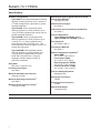
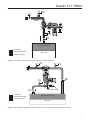
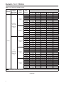
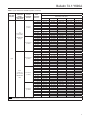
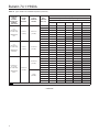
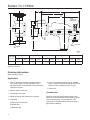
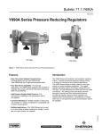
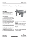
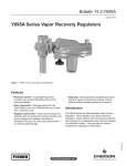
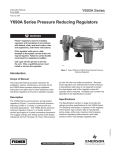
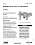
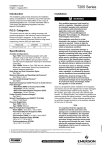
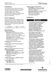
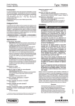
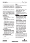
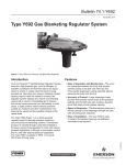
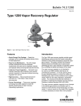
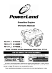
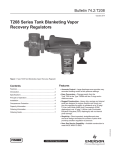
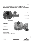
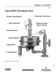
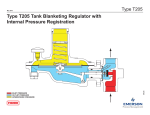
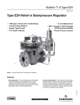
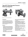
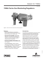
Bulletin 74.1:Y690A
January 2010
Y690A Series Gas Blanketing Regulators
W7293
Figure 1. Y690A Series Direct-Operated Gas Blanketing Regulators
Features
Introduction
• Easy Conversion Between Constructions—
Converts easily from Type Y690A to Type Y690AM
with two O-rings and one machine screw.
The Y690A Series Gas Blanketing Regulator System
reduces a high-pressure gas, such as nitrogen,
to maintain a protective environment above any
liquid stored in a tank or vessel. The regulator
system replaces the volume of vapors with a
volume of blanketing gas to prevent the internal
vessel pressure from decreasing, when liquid is
being pumped out or when the vessel is suddenly
cooled, causing vapors to contract. In both cases
a slight positive vessel pressure prevents outside
air, moisture and other contaminants from entering
the vessel. Type Y690A (Figure 1) is a direct-operated
regulator used for accurate pressure control on very
low-pressure blanketing systems. Downstream
pressure is sensed through a pitot tube installed in
the lower casing of the regulator, thus no external
control line is required. Type Y690AM uses a
control line to more accurately control the pressure
if the regulator is mounted away from the tank.
• Sour Gas Service Capability—For sour gas
applications, the Y690A Series regulators are
available in materials that comply with National
Association of Corrosion Engineers (NACE)
Standards MR0175 and MR0103.
• Inlet Pressure Equals Outlet Pressure—Full
inlet pressure capability on the downstream side
of the regulator.
• Corrosion Resistance—Multiple regulator
constructions are available in a variety of materials
for compatibility with corrosive process gases.
D102591X012
• Multiple Applications—Y690A Series can be used
for a wide variety of gases including air, nitrogen,
natural gas, sour gas, butane, and propane.
www.fisherregulators.com
Bulletin 74.1:Y690A
Specifications
Available Configurations
Type Y690A: Direct-operated pressure reducing regulator for outlet pressures up to 7-inches w.c. (17 mbar) equipped with a pitot tube for greater regulated capacities.
Type Y690AH: Direct-operated pressure
reducing regulator for outlet pressures up to
7 psig (0,48 bar) equipped with a pitot tube for greater regulated capacities.
Type Y690AM: Direct-operated pressure reducing regulator for outlet pressures up to
7-inches w.c. (17 mbar) equipped with a
blocked throat and O-ring stem seal. The lower diaphragm casing is tapped 1/2 NPT for control line connection.
Type Y690AHM: Direct-operated pressure reducing regulator for outlet pressures up to
7 psig (0,48 bar) equipped with a blocked
throat and O-ring stem seal. The lower diaphragm casing is tapped 1/2 NPT for control line connection.
Body Sizes
NPS 3/4 or 1 (DN 20 or 25)
End Connection Styles
See Table 1
Maximum Allowable Inlet Pressure(1)
150 psig (10,3 bar)
Maximum Operating Inlet Pressure(1)
See Table 4
Maximum Outlet Pressure (Casing)(1)
150 psig (10,3 bar)
Maximum Emergency Outlet Pressure to Avoid
Internal Parts Damage(1)
150 psig (10,3 bar)
Outlet Pressure Ranges(1)
See Table 5
Orifice Sizes and Flow and Sizing Coefficients
See Table 2
Pressure Registration
Types Y690A and Y690AH: Internal
Types Y690AM and Y690AHM: External
Flow Capacities
See Tables 9 and 10
Construction Materials
See Table 3
Material Temperature Capabilities(1)
Nitrile (NBR):
-20° to 180°F (-29° to 82°C)
Fluorocarbon (FKM):
40° to 300°F (4° to 149°C)
Ethylenepropylene (EPDM):
-20° to 275°F (-29° to 135°C)
Perfluoroelastomer (FFKM):
-20° to 300°F (-29° to 149°C)
Pressure Setting Adjustment
Adjusting Screw
Spring Case Connection
1/4 NPT
Diaphragm Case Connection
1/2 NPT
Approximate Weight
19 pounds (9 kg)
1. The pressure/temperature limits in this Bulletin and any applicable standard or code limitation should not be exceeded.
2
Bulletin 74.1:Y690A
Table 1. End Connection Styles
END CONNECTION STYLE
BODY SIZE,
NPS (DN)
3/4 or 1
(20 or 25)
Ductile Iron
Stainless Steel
NPT
NPT, SWE,
CL150 RF,
CL300 RF, or
PN 16/25/40
Table 2. Orifice Sizes and Flow and Sizing Coefficients
WIDE-OPEN FOR RELIEF
VALVE SIZING
ORIFICE SIZE,
INCHES (mm)
1/8
1/4
3/8
1/2
9/16
(3,2)
(6,4)
(9,5)
(13)
(14)
Cg
CV
12.3
50
110
200
250
0.35
1.43
3.14
5.71
7.14
IEC SIZING COEFFICIENTS
C1
35
XT
FD
FL
0.78
0.50
0.89
Table 3. Construction Materials
BODY
DIAPHRAGM CASE
Ductile iron or
CF8M Stainless steel
Ductile iron or
CF8M Stainless steel
SPRING CASE
Ductile iron or
CF8M Stainless steel
TRIM
DIAPHRAGM
DISK
303 Stainless steel,
316 Stainless steel
Nitrile (NBR),
Fluorocarbon (FKM), or
Polytetrafluoroethylene
(PTFE) bonded
Nitrile (NBR)
Nitrile (NBR),
Fluorocarbon (FKM),
Perfluoroelastomer (FFKM),
PTFE, or
Ethylenepropylene (EPDM)
Table 4. Maximum Operating Inlet Pressures in Psig (bar)
OUTLET PRESSURE RANGES
ORIFICE
SIZE,
INCHES (mm)
Type Y690A
Types Y690AH and Y690AM
1 to
2.5-Inches w.c.
(2 to 6 mbar)
2.5 to
7-Inches w.c.
(6 to 17 mbar)
1/8 (3,2)
150 (10,3)
150 (10,3)
150 (10,3)
150 (10,3)
150 (10,3)
150 (10,3)
150 (10,3)
150 (10,3)
1/4 (6,4)
3/8 (9,5)
40 (2,8)
20 (1,4)
60 (4,1)
20 (1,4)
75 (5,2)
35 (2,4)
75 (5,2)
35 (2,4)
75 (5,2)
35 (2,4)
150 (10,3)
60 (4,1)
150 (10,3)
60 (4,1)
150 (10,3)
60 (4,1)
10 (0,69)
5 (0,34)
10 (0,69)
5 (0,34)
10 (0,69)
6 (0,41)
12 (0,83)
8 (0,55)
12 (0,83)
8 (0,55)
1/2 (13)
9/16 (14)
5 to
7 to
10-Inches w.c. 16-Inches w.c.
(12 to 25 mbar) (17 to 40 mbar)
8 (0,55)
5 (0,34)
8 (0,55)
5 (0,34)
15-Inches w.c. 1.2 to 2.5 Psig
2.5 to 4.5 Psig
4.5 to 7 Psig
to 1.2 Psig
(83 mbar
(0,17 to 0,31 bar) (0,31 to 0,48 bar)
(37 to 83 mbar) to 0,17 bar)
8 (0,55)
5 (0,34)
Table 5. Outlet (Control) Pressure Ranges and Spring Part Numbers
TYPES
Y690A and
Y690AM
Y690AH and
Y690AHM
OUTLET (CONTROL)
PRESSURE RANGE
1 to 2.5-inches w.c. (2 to 6 mbar)
2.5 to 7-inches w.c. (6 to 17 mbar)
5 to 10-inches w.c. (12 to 25 mbar)
7 to 16-inches w.c. (17 to 40 mbar)
15-inches w.c. to 1.2 psig (37 to 83 mbar)
1.2 to 2.5 psig (83 mbar to 0,17 bar)
2.5 to 4.5 psig (0,17 to 0,31 bar)
4.5 to 7 psig (0,31 to 0,48 bar)
SPRING PART
NUMBER
SPRING
COLOR
SPRING WIRE DIAMETER,
INCHES (mm)
SPRING FREE LENGTH,
INCHES (mm)
1B558527052(1)(2)
1B653827052(1)
Orange
Red
0.072 (1,83)
0.085 (2,16)
3.78 (96,0)
3.63 (92,2)
1B653827052
1B653927022
1B537027052
Red
Unpainted
Yellow
0.085 (2,16)
0.105 (2,67)
0.114 (2,90)
3.63 (92,2)
3.75 (95,2)
4.31 (109)
1B537127022
1B537227022
1B537327052
Light green
Light blue
Black
0.156 (3,96)
0.187 (4,75)
0.218 (5,54)
4.06 (103)
3.94 (100)
3.98 (101)
1. To achieve the published outlet pressure range the spring case must be installed pointing down.
2. Do not use fluorocarbon (FKM) diaphragm with this spring at diaphragm temperatures lower than 60°F (16°C).
3
Bulletin 74.1:Y690A
VALVE DISK
DOWNSTREAM CONTROL LINE FOR
TYPES Y690AM AND Y690AHM
LEVER
PITOT TUBE FOR
TYPES Y690A
AND Y690AH
VALVE STEM
SLIDING PUSHER POST
INLET PRESSURE
OUTLET PRESSURE
OVERPRESSURE SPRING
ATMOSPHERIC PRESSURE
B2625
Figure 2. Y690A Series Operational Schematic
Principle of Operation
With Internal Registration
(Refer to Figure 3)
Types Y690A and Y690AH are direct-operated
regulators with internal registration (see Figures 2
and 3). It provides a constant set pressure for
accurate gas blanketing. When vessel pressure
decreases below the control spring setpoint, the force
of the spring moves the disk away from the orifice
allowing gas to flow into the vessel. As the vessel
pressure increases, the increase is sensed by the
diaphragm through the pitot tube. This movement
of the diaphragm causes the disk to move toward the
orifice, decreasing the flow of blanketing gas. When
the vessel pressure reaches the system setpoint,
the disk will seat against the orifice shutting off the
flow of gas.
With External Registration
(Refer to Figure 4)
Types Y690AM and Y690AHM Gas Blanketing
Regulators reduce a higher-pressure gas to maintain
a positive low pressure of blanket gas over a stored
liquid. Also when the vessel (or tank) is suddenly
cooled, causing vapors to contract, the regulator
4
replaces the volume of contracting vapors with a
volume of blanketing gas to prevent the internal vessel
pressure from decreasing. In both cases, a positive
vessel pressure prevents outside air from entering the
vessel and reduces the possibility of atmospheric
pressure collapsing the vessel.
Gas blanketing regulators respond to a slight decrease
in internal vessel pressure (caused by pump out or
atmospheric cooling) by throttling open to increase the
flow rate of gas into the vessel. When the vessel’s
liquid level has been lowered to the desired point
and the vapor pressure has been reestablished, the
regulator throttles close.
When the liquid level drops and vessel pressure
decreases below the setting of the control spring,
the spring force on the diaphragm opens the disk
assembly to supply the required flow of gas to the
vessel. When vessel pressure has been satisfied,
outlet pressure tends to increase slightly, acting on
the diaphragm. When the outlet pressure exceeds
the control spring setting, the diaphragm moves to
close the disk assembly.
Bulletin 74.1:Y690A
VENT
VALVE
BLOCK
VALVE
SUPPLY
PRESSURE
VENT
VALVE
BLOCK
VALVE
GAS BLANKETING PRESSURE
INLET PRESSURE
GAS BLANKETING PRESSURE
VESSEL/TANK
ATMOSPHERIC PRESSURE
Figure 3. Type Y690A or Y690AH with Internal Registration Operational Schematic
VENT
VALVE
VENT
VALVE
BLOCK
VALVE
BLOCK
VALVE
VENT
VALVE
BLOCK
VALVE
INLET PRESSURE
GAS BLANKETING PRESSURE
VENT POINTED DOWN
GAS BLANKETING PRESSURE
ATMOSPHERIC PRESSURE
VESSEL/TANK
Figure 4. Type Y690AM or Y690AHM Gas Blanketing Regulator with External Registration Operational Schematic
5
Bulletin 74.1:Y690A
Table 6. Vessel Capacity
Table 7. Correction Factors (for converting nitrogen flow rates
to other gas flow rates)
VESSEL CAPACITY
Barrels
Gallons
Liters
60
100
500
1000
2000
2500
4200
21 000
42 000
84 000
9500
16 000
79 500
159 000
318 000
SCFH (Nm3/h) AIR FLOW
RATE REQUIRED(1)
60
100
500
1000
2000
(1,6)
(2,7)
(13,4)
(26,8)
(53,6)
3000
4000
5000
10 000
15 000
126 000
168 000
210 000
420 000
630 000
477 000
636 000
795 000
1 590 000
2 385 000
3000
4000
5000
10 000
15 000
(80,4)
(107)
(134)
(268)
(402)
20 000
25 000
30 000
35 000
40 000
840 000
1 050 000
1 260 000
1 470 000
1 680 000
3 180 000
3 975 000
4 769 000
5 564 000
6 359 000
20 000
24 000
28 000
31 000
34 000
(536)
(643)
(750)
(831)
(911)
45 000
50 000
60 000
70 000
80 000
1 890 000
2 100 000
2 520 000
2 940 000
3 360 000
7 154 000
7 949 000
9 539 000
11 129 000
12 718 000
37 000
40 000
44 000
48 000
52 000
(992)
(1072)
(1179)
(1286)
(1394)
90 000
100 000
120 000
140 000
160 000
3 780 000
4 200 000
5 040 000
5 880 000
6 720 000
14 308 000
15 898 000
19 078 000
22 257 000
25 437 000
56 000
60 000
68 000
75 000
82 000
(1501)
(1608)
(1822)
(2010)
(2198)
180 000
7 560 000
28 616 000
90 000 (2412)
BLANKET GAS
SPECIFIC GRAVITY
CORRECTION FACTOR
Natural Gas
0.60
1.270
Air
1.00
0.985
Dry CO2
1.52
0.797
0.985
Correction Factor =
SG
Table 8. Flow Rate Conversion
MULTIPLY MAXIMUM
PUPM RATE IN
BY
TO OBTAIN
U.S. GPM
U.S. GPH
Barrels/hour
Barrels/day
8.021
0.1337
5.615
0.2340
SCFH air required(1)
1. To convert to Nm3/h multiply SCFH by 0.0268.
1. Flash point is below 100°F (38°C) or normal boiling point is below 300°F (149°C).
Product Description
Sliding Pusher Post
Y690A Series Pressure
Reducing Regulators
The diaphragm assembly of the regulator is equipped
with a sliding pusher post. During an overpressure
situation (outlet pressure above setpoint or lockup
pressure), the spring of the sliding pusher post is
compressed, allowing the diaphragm head to come
to rest on the spring case. This action prevents any
damage to internal parts.
Very low-pressure (Types Y690A and Y690AM)
and higher-pressure versions (Types Y690AH and
Y690AHM) are available for operating inlet pressures
up to 150 psig (10,3 bar) and outlet pressures settings
from 1-inch w.c. to 7 psig (2 mbar to 0,48 bar). Refer
to Table 5 for outlet pressure ranges of each type.
These regulators are available in NPS 3/4 and 1
(DN 20 and 25) body sizes with the end connections
as shown in Table 1.
Downstream Control Line
Types Y690AM and Y690AHM regulators have
a blocked throat stem seal with O-rings and a
1/2 NPT control line connection in the diaphragm
case (Figure 2). The control line can be used to
more accurately control the pressure in the tank if the
regulator is mounted an extended distance from the
control point. The stem seal separates the body outlet
pressure from the diaphragm case.
6
Sizing Blanketing Systems
When sizing a gas blanketing regulator system for
a low-pressure blanketing application, you must
consider the replacement of blanketing gas required
for the liquid loss during pump out of the vessel plus
the condensation/contraction of vessel vapors during
atmospheric thermal cooling. Using the established
procedures from American Petroleum Institute
Standard 2000 (API 2000), determine the flow rate of
blanketing gas required.
1. Determine the gas flow rate required to replace
the liquid being pumped out (see Table 8).
2. Determine the gas flow rate due to “inbreathing”
caused by atmospheric thermal cooling
(see Table 6).
Bulletin 74.1:Y690A
3. Add the requirements of 1 and 2 and select
regulator size, based on total capacity required
from Table 9 or 10.
Sample sizing problem for blanketing applications:
Vessel Capacity . . . . . . . . . . . . 12 500 gallons (47 318 l)
Pump In/Out Capacity . . . . . . . . . 120 GPM (454 l/min)
Inlet Pressure Source . . . . . . . 60 psig (4,1 bar) Nitrogen
Desired Blanket Setpoint . . . . . . 3.0-inches w.c. (7 mbar)
1. From Table 8, the desired air flow rate due to
pump out equals 120 GPM (454 l/min) x 8.021
= 963 SCFH (25,8 Nm³/h) air.
2. From Table 6, interpolate to determine the
required air flow due to thermal cooling
= 300 SCFH (8,0 Nm³/h) air.
3. Total flow required for pump out and thermal cooling
is 963 + 300 = 1263 SCFH (33,8 Nm³/h) air.
4. Convert to nitrogen by dividing the total air flow by
the square root of the specific gravity of nitrogen:
1263 divided by square root of 0.97 = 1282 SCFH
(34,4 Nm³/h) nitrogen.
5. From Table 9, an NPS 1 (DN 25) body size
Type Y690A with a 1/4-inch (6,4 mm) orifice will
flow 1323 SCFH (35,5 Nm³/h) nitrogen at 60 psig
(4,1 bar) inlet pressure. This will satisfy the
required flow of 1282 SCFH (34,4 Nm³/h) nitrogen.
Installation
Types Y690A and Y690AH
Install the regulator with the spring case barrel pointed
down. This will assure that the lowest set pressure
shown in Table 5 is achieved. Flow through the
regulator body is indicated by the flow arrow cast on
the body. If a block valve is required, install a full flow
valve between the regulator and the blanketed vessel.
Types Y690AM and Y690AHM
The regulator may be installed in any position as
long as the flow through the body is in the direction
indicated by the flow arrow attached to the body. Install
the regulator as close as possible to the blanketed
vessel using a straight run of pipe the same size as
or larger than the regulator body. Position the body
and/or diaphragm spring case so it will not collect
moisture or debris into the screened vent and also be
self draining (as shown in Figure 4). If a block valve is
required, install a full flow valve between the regulator
and the blanketed vessel.
Attach a downstream pressure control line to the
1/2 NPT connection in the lower diaphragm case.
Connect the other end of the control line to the vessel.
To allow for self-drainage, install the control line at an
angle so that any liquid material will drain away from
the regulator. See Figures 2 and 4 for the location
of the external control line connection. External
dimensions and connections are shown in Figure 5.
Universal NACE Compliance
Optional materials are available for applications
handling sour gases. These constructions comply
with the recommendations of National Association of
Corrosion Engineers (NACE) sour service standards.
The manufacturing processes and materials used
by Emerson assure that all products specified for
sour gas service comply with the chemical, physical,
and metallurgical requirements of NACE MR0175/
ISO 15156 and/or NACE MR0103. Customers
have the responsibility to specify correct materials.
Environmental limitations may apply and shall be
determined by the user.
Capacity Information
Capacity tables are based on 0.97 specific gravity
nitrogen. Nitrogen is the most common blanketing
gas. Should you use a different gas, convert the
tabular values as follows. For blanketing (pad) gases
other than nitrogen, multiply the given nitrogen flow
rate by the correction factors in Table 7. For gases
of other specific gravities, multiply the given nitrogen
flow rate by 0.985, and divide by the square root of the
appropriate specific gravity.
Q=
520
GT
CgP1Sin
3417
P
C1
P1
Deg
To determine wide-open flow capacities for relief
sizing, use the following formula:
where,
Cg = gas sizing coefficient from Table 2
C1 = Cg /Cv, or 35 from Table 2
G = gas specific gravity (air = 1.0)
P1abs = inlet pressure, psia (add 14.7 psi to gauge inlet
pressure to obtain absolute inlet pressure)
Q = flow rate, SCFH
T
= absolute temperature in °Rankine of gas at inlet
7
Bulletin 74.1:Y690A
Table 9. Types Y690A and Y690AM Capacities
BODY SIZE,
NPS (DN)
OUTLET
PRESSURE
RANGE,
PART NUMBER,
AND COLOR
OUTLET
PRESSURE
SETTING
1-inch w.c.
(2 mbar)
1 to
2.5-inches w.c.
(2 to 6 mbar)
1B558527052
Orange
2.5-inches w.c.
(6 mbar)
2.5-inches w.c.
(6 mbar)
3/4 (20)
2.5 to
7-inches w.c.
(6 to 17 mbar)
3-inches w.c.
(7 mbar)
1B653827052
Red
7-inches w.c.
(17 mbar)
INLET
PRESSURE,
PSIG (bar)
2
5
10
20
40
60
(0,14)
(0,34)
(0,69)
(1,4)
(2,8)
(4,1)
CAPACITIES IN SCFH (Nm3/h) OF NITROGEN(1)
Orifice Size, Inches (mm)
1/8 (3,2)
1/4 (6,4)
3/8 (9,5)
1/2 (13)
9/16 (14)
122
183
204
285
611
814
305
417
591
621
987
(8,2)
(11,2)
(15,8)
(16,6)
(26,4)
356
458
540
662
(9,5)
(12,3)
(14,5)
(17,7)
468 (12,5)
611 (16,4)
814 (21,8)
611 (16,4)
713 (19,1)
356
509
672
784
1038
(9,5)
(13,6)
(18,0)
(21,0)
(27,8)
407
611
764
967
(10,9)
(16,4)
(20,5)
(25,9)
652 (17,5)
835 (22,4)
1038 (27,8)
784 (21,0)
967 (25,9)
204
275
458
641
886
1273
(5,5)
(7,4)
(12,3)
(17,2)
(23,7)
(34,1)
234
540
713
916
(6,3)
(14,5)
(19,1)
(24,5)
458 (12,3)
611 (16,4)
825 (22,1)
499 (13,4)
692 (18,5)
193
275
458
641
875
1069
(5,2)
(7,4)
(12,3)
(17,2)
(23,5)
(28,6)
234
509
713
916
(6,3)
(13,6)
(19,1)
(24,5)
428 (11,5)
621 (16,6)
804 (21,5)
468 (12,5)
692 (18,5)
163
224
407
550
733
1018
(4,4)
(6,0)
(10,9)
(14,7)
(19,6)
(27,3)
193
448
672
957
(5,2)
(12,0)
(18,0)
(25,6)
316 (8,5)
529 (14,2)
774 (20,7)
407 (10,9)
611 (16,4)
(3,3)
(4,9)
(5,5)
(7,6)
(16,4)
(21,8)
80 (5,5)
916 (24,5)
100 (6,9)
1018 (27,3)
125 (8,6)
1222 (32,8)
150 (10,3)
1323 (35,5)
2
5
10
20
40
60
80
100
125
150
2
5
10
20
40
60
80
100
125
150
2
5
10
20
40
60
80
100
125
150
2
5
10
20
40
60
80
100
125
150
122
204
224
285
662
916
1069
1171
1222
1273
122
183
234
255
611
794
967
1028
1171
1232
112
132
193
255
590
723
1008
1150
1303
1354
122
193
204
224
499
611
682
804
855
1079
(0,14)
(0,34)
(0,69)
(1,4)
(2,8)
(4,1)
(5,5)
(6,9)
(8,6)
(10,3)
(0,14)
(0,34)
(0,69)
(1,4)
(2,8)
(4,1)
(5,5)
(6,9)
(8,6)
(10,3)
(0,14)
(0,34)
(0,69)
(1,4)
(2,8)
(4,1)
(5,5)
(6,9)
(8,6)
(10,3)
(0,14)
(0,34)
(0,69)
(1,4)
(2,8)
(4,1)
(5,5)
(6,9)
(8,6)
(10,3)
(3,3)
(5,5)
(6,0)
(7,6)
(17,7)
(24,5)
(28,6)
(31,4)
(32,8)
(34,1)
(3,3)
(4,9)
(6,3)
(6,8)
(16,4)
(21,3)
(25,9)
(27,6)
(31,4)
(33,0)
(3,0)
(3,5)
(5,2)
(6,8)
(15,8)
(19,4)
(27,0)
(30,8)
(34,9)
(36,3)
(3,3)
(5,2)
(5,5)
(6,0)
(13,4)
(16,4)
(18,3)
(21,5)
(22,9)
(28,9)
- Shaded areas indicate maximum allowable inlet pressure is exceeded.
1. Deviation from setpoint is -1 to 2-inches w.c. (-2 to 5 mbar).
- continued -
8
Bulletin 74.1:Y690A
Table 9. Types Y690A and Y690AM Capacities (continued)
BODY SIZE,
NPS (DN)
OUTLET
PRESSURE
RANGE,
PART NUMBER,
AND COLOR
OUTLET
PRESSURE
SETTING
1-inch w.c.
(2 mbar)
1 to
2.5-inches w.c.
(2 to 6 mbar)
1B558527052
Orange
2.5-inches w.c.
(6 mbar)
2.5-inches w.c.
(6 mbar)
1 (25)
2.5 to
7-inches w.c.
(6 to 17 mbar)
3-inches w.c.
(7 mbar)
1B653827052
Red
7-inches w.c.
(17 mbar)
INLET
PRESSURE,
PSIG (bar)
2
5
10
20
40
60
80
100
125
150
2
5
10
20
40
60
80
100
125
150
2
5
10
20
40
60
80
100
125
150
2
5
10
20
40
60
80
100
125
150
2
5
10
20
40
60
80
100
125
150
(0,14)
(0,34)
(0,69)
(1,4)
(2,8)
(4,1)
(5,5)
(6,9)
(8,6)
(10,3)
(0,14)
(0,34)
(0,69)
(1,4)
(2,8)
(4,1)
(5,5)
(6,9)
(8,6)
(10,3)
(0,14)
(0,34)
(0,69)
(1,4)
(2,8)
(4,1)
(5,5)
(6,9)
(8,6)
(10,3)
(0,14)
(0,34)
(0,69)
(1,4)
(2,8)
(4,1)
(5,5)
(6,9)
(8,6)
(10,3)
(0,14)
(0,34)
(0,69)
(1,4)
(2,8)
(4,1)
(5,5)
(6,9)
(8,6)
(10,3)
CAPACITIES IN SCFH (Nm3/h) OF NITROGEN(1)
Orifice Size, Inches (mm)
1/8 (3,2)
112
193
244
356
662
977
1191
1323
1395
1446
122
204
244
356
611
957
1191
1323
1415
1537
112
183
265
326
590
896
1028
1222
1303
1425
102
173
255
305
519
764
1018
1222
1303
1425
102
173
204
285
407
580
662
764
875
1150
(3,0)
(5,2)
(6,5)
(9,5)
(17,7)
(26,2)
(31,9)
(35,5)
(37,4)
(38,7)
(3,3)
(5,5)
(6,5)
(9,5)
(16,4)
(25,6)
(31,9)
(35,5)
(37,9)
(41,2)
(3,0)
(4,9)
(7,1)
(8,7)
(15,8)
(24,0)
(27,6)
(32,8)
(34,9)
(38,2)
(2,7)
(4,6)
(6,8)
(8,2)
(13,9)
(20,5)
(27,3)
(32,8)
(34,9)
(38,2)
(2,7)
(4,6)
(5,5)
(7,6)
(10,9)
(15,5)
(17,7)
(20,5)
(23,5)
(30,8)
1/2 (13)
9/16 (14)
316
356
814
947
1140
1/4 (6,4)
(8,5)
(9,5)
(21,8)
(25,4)
(30,6)
468
1008
1140
1344
3/8 (9,5)
(12,5)
(27,0)
(30,6)
(36,0)
489 (13,1)
1120 (30,0)
1547 (41,5)
967 (25,9)
1161 (31,1)
295
356
753
916
1252
(7,9)
(9,5)
(20,2)
(24,6)
(33,6)
346
753
957
1273
(9,3)
(20,2)
(25,6)
(34,1)
478 (12,8)
947 (25,4)
1262 (33,8)
804 (21,5)
1161 (31,1)
132
305
611
672
987
1323
(3,5)
(8,2)
(16,4)
(18,0)
(26,5)
(35,5)
275
601
814
1161
(7,4)
(16,1)
(21,8)
(31,1)
478 (12,8)
774 (20,7)
1099 (29,5)
641 (17,2)
875 (23,4)
153
305
540
672
987
1323
(4,1)
(8,2)
(14,5)
(18,0)
(26,5)
(35,5)
204
570
723
1028
(5,5)
(15,3)
(19,4)
(27,6)
448 (12,0)
570 (15,3)
855 (22,9)
509 (13,6)
682 (18,3)
153
305
387
621
794
1323
(4,1)
(8,2)
(10,4)
(16,6)
(21,3)
(35,5)
204
438
590
794
(5,5)
(11,7)
(15,8)
(21,3)
377 (10,1)
540 (14,5)
845 (22,6)
397 (10,6)
672 (18,0)
- Shaded areas indicate maximum allowable inlet pressure is exceeded.
1. Deviation from setpoint is -1 to 2.0-inches w.c. (-2 to 5 mbar).
9
Bulletin 74.1:Y690A
Table 10. Types Y690AH and Y690AHM Capacities
OUTLET
PRESSURE
RANGE,
CONTROL
SPRING PART
NUMBER,
AND COLOR
NPS 3/4 (DN 20) BODY SIZE
OFFSET
FROM
SETPOINT
OUTLET
PRESSURE
SETTING
1 (69 mbar)
5 to
10-inches w.c.
(12 to 25 mbar)
1B653827052
Red
1-inch w.c.
(2 mbar)
7-inches w.c.
(17 mbar)
1B653927022
Unpainted
15-inches w.c.
(37 mbar)
15-inches w.c.
to 1.2 psig
(37 mbar to
83 mbar)
5.5-inches w.c.
(14 mbar)
1B537027052
Yellow
1.2 psig
(83 mbar)
1/4 (6,4)
3/8 (9,5)
1/2 (13)
9/16 (14)
71 (1,9)
183 (4,9)
193 (5,2)
326 (8,7)
346 (9,3)
356 (9,5)
387 (10,4)
407 (10,9)
764 (20,5)
8 (0,55)
468 (12,5)
183 (4,9)
417 (11,2)
428 (11,5)
20 (1,4)
407 (10,9)
489 (13,1)
509 (13,6)
35 (2,4)
519 (13,9)
662 (17,7)
713 (19,1)
611 (16,4)
753 (20,2)
1 (69 mbar)
11-inches w.c.
(27 mbar)
1/8 (3,2)
173 (4,6)
75 (5,2)
1-inch w.c.
(2 mbar)
Orifice Size, Inches (mm)
5 (0,34)
150 (10,3)
7 to
16-inches w.c.
(17 to 40 mbar)
Capacities in SCFH (Nm³/h) of Nitrogen
INLET
PRESSURE,
PSIG (bar)
1323 (35,5)
71 (1,9)
122 (3,3)
153 (4,1)
183 (4,9)
193 (5,2)
5 (0,34)
122 (3,3)
224 (6,0)
275 (7,4)
417 (11,2)
590 (15,8)
8 (0,55)
428 (11,5)
132 (3,5)
336 (9,0)
356 (9,5)
20 (1,4)
275 (7,4)
468 (12,5)
478 (12,8)
35 (2,4)
407 (10,9)
489 (13,1)
509 (13,6)
75 (5,2)
509 (13,6)
743 (19,9)
150 (10,3)
1323 (35,5)
2 (0,14)
71 (1,9)
397 (10,6)
713 (19,1)
865 (23,2)
6 (0,41)
193 (5,2)
733 (19,6)
1293 (34,7)
1659 (44,5)
10 (0,69)
265 (7,1)
1089 (29,2)
1527 (40,9)
30 (2,1)
540 (14,5)
1883 (50,5)
1934 (51,8)
60 (4,1)
916 (24,5)
2749 (73,7)
150 (10,3)
2026 (54,3)
2 (0,14)
71 (1,9)
326 (8,7)
478 (12,8)
641 (17,2)
6 (0,41)
193 (5,2)
550 (14,7)
1018 (27,3)
1120 (30,0)
10 (0,69)
244 (6,5)
804 (21,5)
1120 (30,0)
30 (2,1)
529 (14,2)
1629 (43,7)
1914 (51,3)
60 (4,1)
896 (24,0)
2647 (70,9)
150 (10,3)
1955 (52,4)
- Shaded areas indicate inlet pressure is too high for orifice size.
- continued -
10
906 (24,3)
550 (14,7)
Bulletin 74.1:Y690A
Table 10. Types Y690AH and Y690AHM Capacities (continued)
OUTLET
PRESSURE
RANGE,
CONTROL
SPRING PART
NUMBER,
AND COLOR
1.2 to 2.5 psig
(83 mbar to
0,17 bar)
NPS 3/4 (DN 20) BODY SIZE
OFFSET
FROM
SETPOINT
OUTLET
PRESSURE
SETTING
1.2 psig
(83 mbar)
0.2 psig
(14 mbar)
1B537127022
Light green
2.5 psig
(0,17 bar)
2.5 psig
(0,17 bar)
2.5 to 4.5 psig
(0,17 to 0,31 bar)
1B537227022
Light blue
0.3 psig
(21 mbar)
4.5 psig
(0,31 bar)
4.5 psig
(0,31 bar)
4.5 to 7 psig
(0,31 to 0,48 bar)
1B537327052
Black
Capacities in SCFH (Nm³/h) of Nitrogen
INLET
PRESSURE,
PSIG (bar)
0.7 psig
(48 mbar)
7 psig
(0,48 bar)
Orifice Size, Inches (mm)
1/8 (3,2)
1/4 (6,4)
3/8 (9,5)
1/2 (13)
9/16 (14)
2 (0,14)
92 (2,5)
173 (4,6)
275 (7,4)
387 (10,4)
407 (10,9)
6 (0,41)
143 (3,8)
356 (9,5)
580 (15,5)
672 (18,0)
845 (22,7)
10 (0,69)
153 (4,1)
468 (12,5)
794 (21,3)
926 (24,8)
30 (2,1)
438 (11,7)
1222 (32,8)
1354 (36,3)
60 (4,1)
682 (18,3)
1955 (52,4)
1843 (49,4)
150 (10,3)
1568 (42,0)
4031 (108)
6 (0,41)
102 (2,7)
204 (5,5)
356 (9,5)
468 (12,5)
10 (0,69)
132 (3,5)
387 (10,4)
448 (12,0)
682 (18,3)
30 (2,1)
336 (9,0)
774 (20,7)
814 (21,8)
60 (4,1)
590 (15,8)
1527 (40,9)
1771 (47,5)
150 (10,3)
1171 (31,4)
2647 (70,9)
4 (0,28)
112 (3,0)
153 (4,1)
244 (6,5)
295 (7,9)
377 (10,1)
8 (0,55)
112 (3,0)
285 (7,6)
407 (10,9)
560 (15,0)
631 (16,9)
12 (0,83)
153 (4,1)
387 (10,4)
540 (14,5)
733 (19,6)
30 (2,1)
336 (9,0)
713 (19,1)
875 (23,5)
60 (4,1)
519 (13,9)
1364 (36,6)
1446 (38,8)
150 (10,3)
1242 (33,3)
3644 (97,7)
8 (0,55)
92 (2,5)
193 (5,2)
316 (8,5)
407 (10,9)
12 (0,83)
122 (3,3)
255 (6,8)
417 (11,2)
570 (15,3)
30 (2,1)
234 (6,3)
601 (16,1)
652 (17,5)
60 (4,1)
468 (12,5)
967 (25,9)
1059 (28,4)
150 (10,3)
967 (25,9)
2850 (76,4)
9 (0,62)
153 (4,1)
336 (9,0)
12 (0,83)
163 (4,4)
30 (2,1)
407 (10,9)
60 (4,1)
150 (10,3)
489 (13,1)
733 (19,6)
438 (11,7)
641 (17,2)
906 (24,3)
865 (23,2)
1425 (38,2)
682 (18,3)
1619 (43,4)
2138 (57,3)
1547 (41,5)
3980 (107)
9 (0,62)
122 (3,3)
214 (5,7)
407 (10,9)
489 (13,1)
12 (0,83)
153 (4,1)
295 (7,9)
509 (13,6)
682 (18,3)
30 (2,1)
305 (8,2)
713 (19,1)
1049 (28,1)
60 (4,1)
631 (16,9)
1354 (36,3)
1934 (51,8)
150 (10,3)
1507 (40,4)
3197 (85,7)
540 (14,5)
428 (11,5)
784 (21,0)
519 (13,9)
- Shaded areas indicate inlet pressure is too high for orifice size.
- continued -
11
Bulletin 74.1:Y690A
Table 10. Types Y690AH and Y690AHM Capacities (continued)
OUTLET
PRESSURE
RANGE,
CONTROL
SPRING PART
NUMBER,
AND COLOR
NPS 1 (DN 25) BODY SIZE
OFFSET
FROM
SETPOINT
OUTLET
PRESSURE
SETTING
1B653827052
Red
1-inch w.c.
(2 mbar)
7-inches w.c.
(17 mbar)
1B653927022
Unpainted
1-inch w.c.
(2 mbar)
11-inches w.c.
(27 mbar)
15-inches w.c.
(37 mbar)
15-inches w.c
to 1.2 psig
(37 to 83 mbar)
1B537027052
Yellow
5.5-inches w.c.
(14 mbar)
1.2 psig
(83 mbar)
3/8 (9,5)
1/2 (13)
9/16 (14)
71 (1,9)
193 (5,2)
234 (6,3)
326 (8,7)
417 (11,2)
173 (4,6)
356 (9,5)
896 (24,0)
1496 (40,1)
1517 (40,7)
8 (0,55)
1863 (49,9)
183 (4,9)
417 (11,2)
1690 (45,3)
20 (1,4)
407 (10,9)
1425 (38,2)
926 (24,8)
35 (2,4)
560 (15,0)
1812 (48,6)
733 (19,6)
75 (5,2)
814 (21,8)
1099 (29,5)
150 (10,3)
1323 (35,5)
71 (1,9)
132 (3,5)
163 (4,4)
183 (4,9)
193 (5,2)
5 (0,34)
122 (3,3)
244 (6,5)
407 (10,9)
489 (13,1)
916 (24,6)
8 (0,55)
1150 (30,8)
132 (3,5)
336 (9,0)
916 (24,6)
20 (1,4)
275 (7,4)
611 (16,4)
1283 (34,4)
35 (2,4)
438 (11,7)
1425 (38,2)
937 (25,1)
75 (5,2)
967 (25,9)
1191 (31,9)
150 (10,3)
1374 (36,8)
2 (0,14)
71 (1,9)
397 (10,6)
865 (23,2)
916 (24,6)
6 (0,41)
193 (5,2)
733 (19,6)
1975 (52,9)
2209 (59,2)
10 (0,69)
265 (7,1)
1252 (33,6)
2565 (68,7)
30 (2,1)
540 (14,5)
2229 (59,7)
4306 (115)
60 (4,1)
916 (24,6)
3644 (97,7)
150 (10,3)
2026 (54,3)
2 (0,14)
71 (1,9)
366 (9,8)
865 (23,2)
916 (24,6)
6 (0,41)
193 (5,2)
550 (14,7)
1222 (32,8)
1313 (35,2)
10 (0,69)
255 (6,8)
804 (21,6)
2107 (56,5)
30 (2,1)
529 (14,2)
2016 (54,0)
3624 (97,1)
60 (4,1)
896 (24,0)
3309 (88,7)
150 (10,3)
2026 (54,3)
- Shaded areas indicate inlet pressure is too high for orifice size.
- continued -
12
1/4 (6,4)
5 (0,34)
1 (69 mbar)
7 to
16-inches w.c.
(17 to 40 mbar)
Orifice Size, Inches (mm)
1/8 (3,2)
1 (69 mbar)
5 to
10-inches w.c.
(12 to 25 mbar)
Capacities in SCFH (Nm3/h) of Nitrogen
INLET
PRESSURE,
PSIG (bar)
1140 (30,6)
1018 (27,3)
Bulletin 74.1:Y690A
Table 10. Types Y690AH and Y690AHM Capacities (continued)
OUTLET
PRESSURE
RANGE,
CONTROL
SPRING PART
NUMBER,
AND COLOR
1.2 to 2.5 psig
(83 mbar to
0,17 bar)
NPS 1 (DN 25) BODY SIZE
OFFSET
FROM
SETPOINT
OUTLET
PRESSURE
SETTING
1.2 psig
(83 mbar)
0.2 psig
(14 mbar)
2.5 psig
(0,17 bar)
2.5 psig
(0,17 bar)
1B537227022
Light blue
0.3 psig
(21 mbar)
4.5 psig
(0,31 bar)
4.5 psig
(0,31 bar)
4.5 to 7 psig
(0,31 to 0,48 bar)
1B537327052
Black
Orifice Size, Inches (mm)
1/8 (3,2)
1B537127022
Light green
2.5 to 4.5 psig
(0,17 to 0,31 bar)
Capacities in SCFH (Nm3/h) of Nitrogen
INLET
PRESSURE,
PSIG (bar)
0.7 psig
(48 mbar)
7 psig
(0,48 bar)
1/4 (6,4)
3/8 (9,5)
1/2 (13)
9/16 (14)
2 (0,14)
92 (2,5)
183 (4,9)
366 (9,8)
489 (13,1)
519 (13,9)
6 (0,41)
143 (3,8)
356 (9,5)
865 (23,2)
692 (18,6)
855 (22,9)
10 (0,69)
153 (4,1)
509 (13,6)
1110 (29,8)
1384 (37,1)
30 (2,1)
499 (13,4)
1262 (33,8)
3186 (85,4)
60 (4,1)
794 (21,3)
2840 (76,1)
6067 (163)
150 (10,3)
1924 (51,6)
3054 (81,9)
6 (0,41)
112 (3,0)
214 (5,7)
519 (13,9)
529 (14,2)
10 (0,69)
143 (3,8)
387 (10,4)
611 (16,4)
682 (18,3)
30 (2,1)
448 (12,0)
814 (21,8)
1812 (48,6)
60 (4,1)
672 (18,0)
1985 (53,2)
5813 (156)
150 (10,3)
1731 (46,4)
2749 (73,7)
4 (0,28)
112 (3,0)
153 (4,1)
326 (8,7)
336 (9,0)
377 (10,1)
713 (19,1)
8 (0,55)
143 (3,8)
285 (7,6)
560 (15,0)
580 (15,5)
12 (0,83)
153 (4,1)
387 (10,4)
733 (19,6)
753 (20,2)
30 (2,1)
336 (9,0)
713 (19,1)
1446 (38,8)
60 (4,1)
519 (13,9)
1374 (36,8)
3217 (86,2)
150 (10,3)
1588 (42,6)
5253 (141)
8 (0,55)
92 (2,5)
193 (5,2)
387 (10,4)
407 (10,9)
12 (0,83)
122 (3,3)
255 (6,8)
478 (12,8)
672 (18,0)
30 (2,1)
305 (8,2)
601 (16,1)
1069 (28,7)
60 (4,1)
499 (13,4)
967 (25,9)
2443 (65,5)
150 (10,3)
1099 (29,5)
3940 (106)
9 (0,62)
163 (4,4)
336 (9,0)
12 (0,83)
183 (4,9)
30 (2,1)
407 (10,9)
60 (4,1)
150 (10,3)
662 (17,7)
764 (20,5)
438 (11,7)
794 (21,4)
1018 (27,3)
865 (23,2)
1639 (43,9)
692 (18,6)
1619 (43,4)
2881 (77,2)
1629 (43,7)
4734 (127)
9 (0,62)
122 (3,3)
214 (5,7)
468 (12,5)
489 (13,1)
12 (0,83)
163 (4,4)
295 (7,9)
611 (16,4)
702 (18,8)
30 (2,1)
295 (7,9)
713 (19,1)
1303 (34,9)
60 (4,1)
631 (16,9)
1354 (36,3)
2179 (58,4)
150 (10,3)
1588 (42,6)
3268 (87,6)
540 (14,5)
428 (11,5)
825 (22,1)
519 (13,9)
- Shaded areas indicate inlet pressure is too high for orifice size.
13
Bulletin 74.1:Y690A
G
F
D
8.38
(213)
1/2 NPT
CONTROL LINE
CONNECTION
B
14
(356)
A
NPT
OR
SWE
5.56
(141)
1/4 NPT VENT
FLANGED
INCHES
(mm)
A
BODY SIZE,
NPS (DN)
3/4, 1 (20, 25)
B
D
F
G
Ductile
Iron
Stainless
Steel
Ductile
Iron
Stainless
Steel
Ductile
Iron
Stainless
Steel
Ductile
Iron
Stainless
Steel
Ductile
Iron
Stainless
Steel
4.0 (102)
4.12 (105)
2.12 (54)
2.25 (57)
6.19 (157)
6.19 (157)
10.12 (257)
10.12 (257)
1.53 (39)
1.53 (39)
Figure 5. Dimensions
Ordering Information
When ordering, specify:
Application
1. Type of gas being controlled (nitrogen, fuel gas, etc.); list any factors such as impurities in the gas that may affect compatibility of the gas with the regulator trim parts.
2. Specific gravity of the gas
3. Temperature of the gas
4. Range of flowing inlet pressures to regulator
5. Flow rates
a) Minimum controlled flow
b) Normal flow
c) Maximum flow
14
6. Line size and end connection size of adjacent piping. Adjacent downstream piping must be the same size as the regulator body or longer.
7. Vessel size
Construction
Carefully review the Specifications section, then
specify the desired selection on the Ordering Guide
on the following page. If a pilot setpoint is not
requested, the regulator will be factory set at the
approximate midrange.
Bulletin 74.1:Y690A
Ordering Guide
Type (Select One)
Y690A (Internal registration)***
Y690AH (High-pressure with Internal registration)***
Y690AM (External registration)*** Y690AHM (High-pressure with External registration)***
Body Size (Select One)
NPS 3/4 (DN 20)***
NPS 1 (DN 25)***
Body Material and End Connection Style (Select One)
Ductile iron Body
NPT***
CF8M Stainless steel
NPT***
CL150 RF**
CL300 RF**
PN 16/25/40**
Disk Material (Select One)
Nitrile (NBR) (standard)***
Fluorocarbon (FKM)***
Ethylenepropylene (EPDM)**
PTFE**
Perfluoroelastomer (FFKM)*
Orifice Size (Select One)
1/8-inch (3,2 mm)***
1/4-inch (6,4 mm)***
3/8-inch (9,5 mm)***
1/2-inch (13 mm)***
9/16-inch (14 mm)***
Outlet (Control) Pressure Range (Select One)
Types Y690A and Y690AM
1 to 2.5-inches w.c. (2 to 6 mbar) Orange***
2.5 to 7-inches w.c. (6 to 17 mbar) Red***
Diaphragm Case Material (Select One)
Ductile iron***
CF8M Stainless steel***
Types Y690AH and Y690AHM
5 to 10-inches w.c. (12 to 25 mbar) Red***
7 to 16-inches w.c. (17 to 40 mbar) Unpainted***
15-inches w.c. to 1.2 psig (37 to 83 mbar) Yellow***
1.2 to 2.5 psig (83 mbar to 0,17 bar) Light Green***
2.5 to 4.5 psig (0,17 to 0,31 bar) Light Blue***
4.5 to 7 psig (0,31 to 0,48 bar) Black***
Trim Material (Select One)
303 Stainless steel***
316 Stainless steel**
Replacement Parts Kit (Optional)
Yes, send one replacement parts kit to match
this order.
Spring Case Material (Select One)
Ductile iron***
CF8M Stainless steel***
Diaphragm Material (Select One)
Nitrile (NBR) (standard)***
Fluorocarbon (FKM)**
Nitrile (NBR) with PTFE Protector**
To order this product, complete this page or complete the
Specification Worksheet and forward to your local
Sales Office.
If the construction you need is not offered on this page,
contact your local Sales Office.
To locate your local Sales Office log on to:
www.fisherregulators.com
Regulators Quick Order Guide
***
**
*
Readily Available for Shipment
Allow Additional Time for Shipment
Special Order, Constructed from Non-Stocked Parts.
Consult your local Sales Office for Availability.
Tank Blanketing Specification Worksheet
Application Specifications:
Tank Capacity
Pump In Rate
Pump Out Rate
Blanketing Gas (Type and Specific Gravity)
Conservation Vent Setpoint
Pressure Requirements:
Maximum Inlet Pressure (P1max)
Minimum Inlet Pressure (P1min)
Control Pressure Setting (P2)
Maximum Flow (Qmax)
Accuracy Requirements:
0.25-inch w.c. (0,6 mbar) 0.5-inch w.c. (1 mbar)
1-inch w.c. (2 mbar) 2-inches w.c. (5 mbar)
Others
Other Specifications:
Is a vapor recovery regulator required? Yes No
Special Material Requirements: Ductile Iron Steel
Stainless steel Hastelloy® C Others
Other Requirements:
Availability of the product being ordered is determined by the component with the
longest shipping time for the requested construction.
15
Bulletin 74.1:Y690A
Industrial Regulators
Natural Gas Technologies
TESCOM
Emerson Process Management
Regulator Technologies, Inc.
Emerson Process Management
Regulator Technologies, Inc.
Emerson Process Management
Tescom Corporation
USA - Headquarters
McKinney, Texas 75069-1872 USA
Tel: 1-800-558-5853
Outside U.S. 1-972-548-3574
USA - Headquarters
McKinney, Texas 75069-1872 USA
Tel: 1-800-558-5853
Outside U.S. 1-972-548-3574
USA - Headquarters
Elk River, Minnesota 55330-2445 USA
Tel: 1-763-241-3238
Asia-Pacific
Shanghai, China 201206
Tel: +86 21 2892 9000
Asia-Pacific
Singapore, Singapore 128461
Tel: +65 6777 8211
Europe
Bologna, Italy 40013
Tel: +39 051 4190611
Europe
Bologna, Italy 40013
Tel: +39 051 4190611
Gallardon, France 28320
Tel: +33 (0)2 37 33 47 00
Middle East and Africa
Dubai, United Arab Emirates
Tel: +971 4811 8100
Europe
Selmsdorf, Germany 23923
Tel: +49 (0) 38823 31 0
For further information visit www.fisherregulators.com
The Emerson logo is a trademark and service mark of Emerson Electric Co. All other marks are the property of their prospective owners. Fisher is a mark owned by Fisher Controls, Inc., a
business of Emerson Process Management.
The contents of this publication are presented for informational purposes only, and while every effort has been made to ensure their accuracy, they are not to be construed as warranties or
guarantees, express or implied, regarding the products or services described herein or their use or applicability. We reserve the right to modify or improve the designs or specifications of such
products at any time without notice.
Emerson Process Management does not assume responsibility for the selection, use or maintenance of any product. Responsibility for proper selection, use and maintenance of any Emerson
Process Management product remains solely with the purchaser.
©Emerson Process Management Regulator Technologies, Inc., 1998, 2010; All Rights Reserved