1
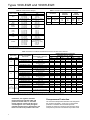
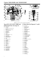
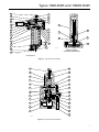
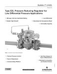
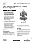
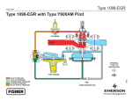
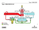
Types 1098-EGR and 1098H-EGR
Installation Guide
English – July 2011
Introduction
Installation
This installation guide provides instructions for
installation, startup, and adjustment. To receive a copy
of the instruction manual, contact your local Sales Office
or view a copy at www.fisherregulators.com. For further
information refer to: Types 1098-EGR and 1098H-EGR
Instruction Manual, form 5084, D100339X012.
Only qualified personnel should install or
service a regulator. Regulators should
be installed, operated, and maintained
in accordance with international and
applicable codes and regulations, and
Fisher instructions.
P.E.D. Categories
If the regulator vents fluid or a leak
develops in the system, it indicates that
service is required. Failure to take the
regulator out of service immediately may
create a hazardous condition.
This product may be used as a safety accessory with
pressure equipment in the following Pressure Equipment
Directive 97/23/EC categories. It may also be used
outside of the Pressure Equipment Directive using sound
engineering practice (SEP) per table below.
product sizes
categories
DN 25 / NPS 1
SEP
DN 50, 80, 100, 150, 200 x 150, 300 x 150 /
NPS 1, 2, 3, 4, 6, 8 x 6, 12 x 6
II
Warning
!
Personal injury, equipment damage, or
leakage due to escaping fluid or bursting of
pressure-containing parts may result if this
regulator is overpressured or is installed
where service conditions could exceed the
limits given in the Specifications section,
or where conditions exceed any ratings of
the adjacent piping or piping connections.
Specifications
To avoid such injury or damage, provide
pressure-relieving or pressure-limiting
devices (as required by the appropriate
code, regulation, or standard) to prevent
service conditions from exceeding limits.
Body Sizes and End Connection Styles
See Table 1
Main Valve Maximum Inlet Pressure(1)
27,6 bar / 400 psig or body rating limit whichever
is lower.
Additionally, physical damage to the
regulator could result in personal injury
and property damage due to escaping fluid.
To avoid such injury and damage, install
the regulator in a safe location.
Maximum Pilot Supply Pressure(1)
41,4 bar / 600 psig
Outlet Pressure Ranges(1)
See Table 2
Clean out all pipelines before installation of the regulator
and check to be sure the regulator has not been damaged
or has collected foreign material during shipping. For
NPT bodies, apply pipe compound to the external pipe
threads. For flanged bodies, use suitable line gaskets
and approved piping and bolting practices. Install the
regulator in any position desired, unless otherwise
specified, but be sure flow through the body is in the
direction indicated by the arrow on the body.
Actuator Sizes and Maximum Pressures(1)
See Table 3
Maximum and Minimum Differential Pressures(1)
See Table 4
Maximum Temperature Capabilities(1)
Nitrile (NBR): -20° to 180°F / -29° to 82°C
Fluorocarbon (FKM): 0° to 300°F / -18° to 149°C,
except water is limited to 0° to 200°F / -18° to 93°C
Ethylenepropylene (EPR): -20° to 275°F / -29° to 135°C
Note
It is important that the regulator be installed
so that the vent hole in the spring case
is unobstructed at all times. For outdoor
1. The pressure/temperature limits in this installation guide and any applicable standard or code limitation should not be exceeded.
BODY SIZES
CAST IRON
STEEL OR STAINLESS STEEL
1, 2
NPT, CL125 FF, or CL250 RF
NPT, CL150 RF, CL300 RF,
CL600 RF, BWE, SWE, or PN 16/25/40
80, 100, 150
3, 4, 6
CL125 FF or CL250 RF
CL150 RF, CL300 RF, CL600 RF,
BWE, or PN 16/25/40
200 x 150, 300 x 150
8 x 6, 12 x 6
----
CL150 RF, CL300 RF, CL600 RF,
or BWE
DN
NPS
25, 50
www.fisherregulators.com
D100339XUS2
Table 1. Body Sizes and End Connection Styles
Types 1098-EGR and 1098H-EGR
Table 2. Outlet Pressure Ranges
pilot types
6351
6352
6353
6354L(1)
6354M(2)
6354H
61L
61LD
61LE
61H
61HP
Y600AM
Table 3. Actuator Sizes and Maximum Pressures
outlet (control) pressure range
bar
psig
0,21 to 1,38
3 to 20
0,34 to 2,41
5 to 35
2,41 to 6,90
35 to 100
35 mbar to 0,14 bar
14-inches w.c. to 2 psig
0,14 to 0,69
2 to 10
0,21 to 2,76
3 to 40
2,41 to 8,62
35 to 125
5,86 to 13,8
85 to 200
12,1 to 15,2
175 to 220
13,8 to 20,7
200 to 300
0,02 to 0,14
0.25 to 2
0,07 to 0,34
1 to 5
0,14 to 0,69
2 to 10
0,34 to 1,03
5 to 15
0,69 to 1,38
10 to 20
0,69 to 4,48
10 to 65
1,03 to 3,10
15 to 45
2,41 to 6,90
35 to 100
6,90 to 20,7
100 to 300
10 to 20 mbar
4 to 8-inches w.c.
7 to 16-inches w.c.
17 to 40 mbar
15-inches w.c. to 1.2 psig
37 to 83 mbar
0,83 to 0,17
1.2 to 2.5
0,17 to 0,31
2.5 to 4.5
0,31 to 0,48
4.5 to 7
Outlet
(CONTROL)
pressure
Actuator
Emergency
casing
pressure
Type
Size
bar
psig
bar
psig
1098
30
40 (standard)
70
6,90
5,17
3,45
100
75
50
7,93
5,65
4,48
115
82
65
1098H
30
24,1
350
27,6
400
1. Without diaphragm limiter.
2. With diaphragm limiter.
Table 4. Maximum and Minimum Differential Pressures for Main Valve Selection
BODY SIZEs
DN
25
NPS
1
SPRING PART NUMBER
AND COLOR
14A9687X012, Green
14A9680X012, Blue
15A2253X012, Yellow
14A9686X012, Green
4,14 / 60
8,62 / 125
27,6 / 400 or body rating limit,
whichever is lower
1,38 / 20
4,14 / 60
8,62 / 125
27,6 / 400 or body rating limit,
whichever is lower
1,38 / 20
4,14 / 60
8,62 / 125
27,6 / 400 or body rating limit,
whichever is lower
1,38 / 20
4,14 / 60
8,62 / 125
27,6 / 400 or body rating limit,
whichever is lower
1,38 / 20
4,14 / 60
14A9685X012, Blue
15A2615X012, Red
14A9679X012, Red
50
2
14A6768X012, Yellow
14A6626X012, Green
14A6627X012, Blue
3
14A6771X012, Yellow
14A6629X012, Green
14A6630X012, Blue
4
14A6770X012, Yellow
14A6632X012, Green
14A6633X012, Blue
14A6628X012, Red
80
14A6631X012, Red
100
14A6634X012, Red
150,
200 x 150,
300 x 150
6,
8 x 6,
12 x 6
Maximum allowable
differential pressure,
bar / psig(1)
Minimum differential pressure
required For full Stroke
Size 30 Actuator
Size 40 Actuator
Size 70 Actuator
bar
psig
bar
psig
bar
psig
0,24
0,34
3.5
5
0,17
0,21
2.5
3
0,07
0,10
1
1.5
0,48
7
0,34
5
0,17
2.5
---0,28
0,41
---4
6
---0,21
0,34
---3
5
0,07
0,10
0,14
1
1.5
2
0,76
11
0,69
10
0,21
3
---0,34
0,55
---5
8
---0,28
0,41
---4
6
0,07
0,14
0,17
1
2
2.5
0,97
14
0,76
11
0,28
4
---0,69
0,90
---10
13
---0,34
0,55
---5
8
0,09
0,17
0,21
1.3
2.5
3
1,52
22
0,90
13
0,34
5
---0,90
---13
---0,66
---9.5
0,15
0,28
2.2
4
8,62 / 125
1,31
19
0,97
14
0,41
6
27,6 / 400 or body rating limit,
whichever is lower
1,93(2)
28(2)
1,31
19
0,55
8
1. Maximum inlet pressure is equal to set pressure plus maximum differential.
2. Requires special 6300 Series pilot construction without integral relief valve and with external Type 1806 2,76 bar d / 40 psid relief valve.
installations, the regulator should be
located away from vehicular traffic and
positioned so that water, ice, and other
foreign materials cannot enter the spring
case through the vent. Avoid placing the
regulator beneath eaves or downspouts, and
be sure it is above the probable snow level.
2
Overpressure Protection
The recommended pressure limitations are stamped on
the regulator nameplate. Some type of overpressure
protection is needed if the actual inlet pressure
exceeds the maximum operating outlet pressure rating.
Overpressure protection should also be provided if the
Types 1098-EGR and 1098H-EGR
21
27
19
10
18
INDICATOR PLUG ASSEMBLY
37
22
7
8
21
35
6
36
3
5
2
31
24
4
26
20
14
23
15
28
9
17
11
16
13
12
24
1
25
35A3167
COMPLETE CAST IRON
FULL-CAPACITY MAIN VALVE ASSEMBLY
Figure 1. Type EGR Main Valve Assembly
regulator inlet pressure is greater than the safe working
pressure of the downstream equipment.
Taking Out of Service (Shutdown)
!
Regulator operation below the maximum pressure
limitations does not preclude the possibility of damage from
external sources or debris in the line. The regulator should
be inspected for damage after any overpressure condition.
Startup
The regulator is factory set at approximately the midpoint
of the spring range or the pressure requested, so an
initial adjustment may be required to give the desired
results. With proper installation completed and relief
valves properly adjusted, slowly open the upstream and
downstream shutoff valves.
Adjustment
To change the outlet pressure, remove the closing cap or
loosen the locknut and turn the adjusting screw clockwise
to increase outlet pressure or counterclockwise to
decrease outlet pressure. Monitor the outlet pressure with
a test gauge during the adjustment. Replace the closing
cap or tighten the locknut to maintain the desired setting.
Warning
To avoid personal injury resulting from
sudden release of pressure, isolate
the regulator from all pressure before
attempting disassembly.
Type EGR Parts List (Figure 1)
Key Description
1
2
3
4
5
6
7
8
9
10
11
12
13
14
15
16
17
18
19
Valve Body
Body Flange
Cap Screw or Stud Bolt
Gasket
Travel Indicator Fitting
O-ring Retainer
Travel Indicator Stem O-Ring
Travel Indicator Hex Nut
Spring
Travel Indicator Stem
Cage
Port Seal
Seat Ring
Piston Ring
Upper Seal
Valve Plug
Cage O-Ring
Travel Indicator Scale
Travel Indicator Protector
Key Description 20
21
Plug O-Ring
Travel Indicator Fitting or
Indicator Plug O-Ring
22 Travel Indicator Flange Nut
23 E-Ring
24 Drive Screw
25 Flow Arrow
26 Body Rating Plate (not shown)
27 Indicator Plug
28 Spring Seat
29 Hex Nut (not shown)
31 Pipe Plug
32 Travel Stop
33 NACE Tag (not shown)
34 Tag Wire (not shown)
35 Fitting
36 Back-up Ring
37 O-Ring
3
Types 1098-EGR and 1098H-EGR
6
8 28
3
56 12
57
28
5
27
56
57
12
27
2
8
29 13
9
1
7
11
10
6
2
57
6
56
6
56
36A8540
Type 1098H
34A5692
13
7
4
9
1
11 10
Type 1098
Figure 2. Types 1098 and 1098H Actuator Assemblies
6
5
2
5
P590 Series Parts List (Figure 3)
Key Description
7
1
4
3
1
2
3
4
5
6
7
11
12
Filter Body
Filter Element
Filter Head
Machine Screw
Washer
Spring Washer
Gasket
NACE Tag (not shown)
Tag Wire (not shown)
A7008
Figure 3. Standard P590 Series Filter Assembly
Types 1098 and 1098H Actuators
Parts List (Figure 2)
Key Description
1
Lower Casing
2
Upper Casing
3
Bonnet
4
Cap Screw
5
Casing O-Ring 6
Stem O-Ring
7 Diaphragm
8
Diaphragm Plate
9
Cap Screw
10 Cap Screw Stud
11 Hex Nut
12 Stem
13 Nameplate (not shown)
27 Vent Insert
28 Zerk Fitting
56 Bearing
54 NACE Tag (not shown)
55 Tag Wire (not shown)
57 Wiper
4
Type 6351 Parts List (Figure 4)
Key Description
1
2
3
4
6
7
8
9
10 11 12 13
14
22 24 28
35 42 43
Body Assembly
Bonnet
Body Plug Assembly
Inner Valve Assembly
Valve Spring
Diaphragm Assembly
Upper Spring Seat
Control Spring
Adjusting Screw
Locknut
Machine Screw
Hex Lock Plate
Threaded Lock Plate
Pipe Nipple
P590 Series Filter
Closing Cap
Vent Assembly
Relief Valve Assembly
Closing Cap Gasket
Types 1098-EGR and 1098H-EGR
10
11
2
8
9
12
7
1
22
24
34A6635-B
4
42
6
3B
3
23
3
CB7988
OLD TYPE 6351 ASSEMBLY DRAWING
SHOWING OLD BODY PLUG AND BODY PLUG GASKET
NEW TYPE 6351 ASSEMBLY DRAWING
SHOWING NEW BODY PLUG AND BODY PLUG o-ring
Figure 4. Type 6351 Pilot Assembly
11
2
14
15
10
7
5
8
1
23
13
9
20
6
22
4
16
3
19
35A8889
21
12
17
35A6236
Detail of Type 6354M or 6354H pilot
Complete Type 6352, 6353, or 6354L pilot
Figure 5. Types 6352 through 6354H Pilot Assemblies
5
Types 1098-EGR and 1098H-EGR
26
3
13
11
16
35
14
1
10
28
20A6328
12
Detail of Capped
Adjusting Screw OPTION
4
24
9
8
1
2
18
17
20
15
25
19
7
50
27
6
5
28
28
35
40
5
22
34
6
33
44
1
43
30A6327
20A6326
Types 61L, 61LD, and 61LE pilot
Detail Handwheel Option
Figure 6. Types 61L, 61LD, and 61LE Pilot Assemblies
Types 6352, 6353, 6354L, 6354M, and
6354H Pilots Parts List (Figure 5)
61 Series Parts List (Figures 6, 7, and 8)
Key Description
1 Relay Spring Case
2 Relay Valve Body
3
Bottom Cover
4 Relay Yoke
5 Closing Cap Assembly
6 Adjusting Screw
7 Control Spring
8 Relay Orifice
9 Disc Holder Assembly
10 Bleed Orifice
11 Diaphragm Nut
12 O-ring Seal
13 Relay Spring
14 Upper Relay Diaphragm
15 Lower Relay Diaphragm
16 Upper Relay Head
17 Lower Relay Head
18 Spring Seat
19 Hex Nut
20 Cap Screw
23 Pipe Plug or Vent Assembly
24 Pipe Nipple
25 Filter Assembly
26 Bleed Valve
27 Nameplate
28 Gasket
30 Pipe Plug
33 Handwheel
34 Hex Nut
35 Spring Seat
40 O-ring
41 Adaptor
42 Yoke Cap
43 Lockwasher
44 Machine Screw
45 Valve Spring Seat
46 Cap Screw
47 Machine Screw
48 Cap Screw
50 Drive Screw
51 Diaphragm Insert
52 Lower Yoke Cap
53 Bleed Plug
54 Vent Assembly
1
2
3
4
5
6
7
8
9
10 11 12 13 14 15 16 17 19 20 21 22 23 26 27 28 29 30 31 32 33 34 35 36 37 38 39 40 6
Pilot Body
Spring Case or Regulator Bonnet
Body Plug
Valve Plug and Stem Assembly
Diaphragm Assembly
Control Spring
Spring Seat
Stem Guide
Adjusting Screw
Locknut
Closing Cap
Body Plug Gasket / O-ring
Vent Assembly
Machine Screw
Relief Valve Assembly
Bellows Assembly
O-ring
Filter
Closing Cap Gasket
Pipe Nipple
Restriction
Diaphragm Limiter
NACE Tag
Tag Wire
Packing Bonnet
Handwheel
Closing Cap
Washer
Screw
Packing Spring
Packing Box Gasket
Packing Follower
External Adaptor
Internal Adaptor
Packing Washer
Packing Ring
Adjusting Screw
Key Description
Types 1098-EGR and 1098H-EGR
30
3
26
10
13
11
14
16
25
5
4
24
20
2
12
15
9
34
28
8
18
7
50
1
27
35
34
23
6
41
17
19
35
30A6330
Detail of Capped
Adjusting Screw OPTION
6
32A2068
Type 61H pilot
Figure 7. Type 61H Pilot Assembly
6
34
7
35
50
1
27
48
16
42
14
10
4
45
26
13
47
2
15
52
51
53
3
19
46
34A0396
Figure 8. Type 61HP Pilot Assembly
7
Types 1098-EGR and 1098H-EGR
Industrial Regulators
Natural Gas Technologies
TESCOM
Emerson Process Management
Regulator Technologies, Inc.
Emerson Process Management
Regulator Technologies, Inc.
Emerson Process Management
Tescom Corporation
USA - Headquarters
McKinney, Texas 75069-1872, USA
Tel: +1 800 558 5853
Outside U.S. +1 972 548 3574
USA - Headquarters
McKinney, Texas 75069-1872, USA
Tel: +1 800 558 5853
Outside U.S. +1 972 548 3574
USA - Headquarters
Elk River, Minnesota 55330-2445, USA
Tels: +1 763 241 3238
+1 800 447 1250
Asia-Pacific
Shanghai 201206, China
Tel: +86 21 2892 9000
Asia-Pacific
Singapore 128461, Singapore
Tel: +65 6770 8337
Europe
Selmsdorf 23923, Germany
Tel: +49 38823 31 287
Europe
Bologna 40013, Italy
Tel: +39 051 419 0611
Europe
Bologna 40013, Italy
Tel: +39 051 419 0611
Gallardon 28320, France
Tel: +33 2 37 33 47 00
Asia-Pacific
Shanghai 201206, China
Tel: +86 21 2892 9499
Middle East and Africa
Dubai, United Arab Emirates
Tel: +971 4811 8100
For further information visit www.fisherregulators.com
The Emerson logo is a trademark and service mark of Emerson Electric Co. All other marks are the property of their prospective owners. Fisher is a mark owned by Fisher Controls, Inc., a
business of Emerson Process Management.
The contents of this publication are presented for informational purposes only, and while every effort has been made to ensure their accuracy, they are not to be construed as warranties or
guarantees, express or implied, regarding the products or services described herein or their use or applicability. We reserve the right to modify or improve the designs or specifications of such
products at any time without notice.
Emerson Process Management does not assume responsibility for the selection, use or maintenance of any product. Responsibility for proper selection, use and maintenance of any Emerson
Process Management product remains solely with the purchaser.
©Emerson Process Management Regulator Technologies, Inc., 2002, 2011; All Rights Reserved