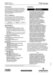
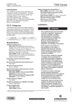
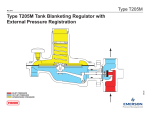
1
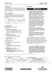
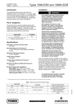
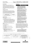
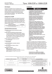
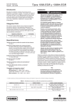
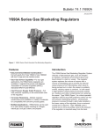
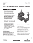
Bulletin 74.1:1190 April 2012 Type 1190 Low-Pressure Gas Blanketing Regulator W7428 Figure 1. Type 1190 Low-Pressure Gas Blanketing Regulator Introduction Features A Type 1190 low-pressure gas blanketing regulator reduces a high-pressure gas, such as Nitrogen, to maintain a protective environment above any liquid stored in a tank or vessel while the liquid is being pumped out. Also, when the vessel cools suddenly causing the vapors inside the vessel to condense, the gas blanketing regulator replaces the condensed vapors with the blanketing gas to prevent the internal vessel pressure from decreasing. In both cases a slight positive vessel pressure prevents outside air, moisture, and other contaminants from entering the vessel and the possible collapse of the vessel walls. • Quick-Change Trim Package—Tested trim packages can be made up and stocked ahead of time for fast replacement. • In-Service Travel Inspection—Standard indicator assembly with protective cover permits periodic inspection of plug travel without removing regulators from service. • Easy In-Line Maintenance—Top-entry design reduces maintenance time and manpower requirements; trim parts can be inspected, cleaned, and replaced without removing the main valve body from the pipeline. • Factory-Piped Pilot Supply—Supply pressure to pilot is supplied from inlet side of the main valve body through tubing furnished with the regulator. www.fisherregulators.com D101962X012 The Type 1190 low-pressure gas blanketing regulator is used for extremely accurate pressure control on very low-pressure blanketing systems. The regulator helps to control emissions and provides protection against any contamination from atmospheric conditions by providing a flushing action. The Type 1190 gas blanketing regulator maintains a positive vessel pressure thereby reducing the possibility of vessel wall collapse during pump-out operations. Bulletin 74.1:1190 Specifications Body Sizes(1) See Table 1 Control Line Connection Maximum Main Valve Inlet Pressures(2) 400 psig / 27.6 bar Vent Connection on Pilot Spring Case Maximum Operating Inlet Pressures(2) 200 psig / 13.8 bar with cast iron construction or 300 psig / 20.7 bar with a steel or stainless steel construction Temperature Capabilities(2) Maximum Outlet (Casing) Pressure(2) 75 psig / 5.2 bar Maximum Operating Outlet Pressure to Avoid Internal Part Damage(2) 75 psig / 5.2 bar Outlet Pressure Ranges (Type Y191A Pilot)(2) See Table 2 Main Valve Orifice Diameters and Travels See Table 3 Proportional Bands See Table 4 Maximum and Minimum Differential Pressures See Table 5 Flow Coefficients for Relief Valve Sizing See Table 8 Flow Coefficients for Fixed Restriction Cg: 3; Cv: 11.7; C1: 35 Supply Pressure Settings Required for the Type 95H Supply Pressure Regulator See Table 9 Flow Capacities See Table 10 Pressure Registration External Main Valve Flow Characteristic Linear 3/4 NPT 1/4 NPT Nitrile (NBR): -20 to 180°F / -29 to 82°C Fluorocarbon (FKM): 40 to 300°F / 4 to 149°C Ethylenepropylene (EPDM): -20 to 275°F / -29 to 135°C Perfluoroelastomer (FFKM): -20 to 300°F / -29 to 149°C Approximate Weights NPS 1 / DN 25: 85 pounds / 39 kg NPS 2 / DN 50: 100 pounds / 45 kg NPS 3 / DN 80: 145 pounds / 66 kg NPS 4 / DN 100: 195 pounds / 88 kg NPS 6 / DN 150: 380 pounds / 172 kg NPS 8 x 6 / DN 200 x 150: 740 pounds / 336 kg NPS 12 x 6 / DN 300 x 150: 1265 pounds / 574 kg Construction Materials Type EGR Main Valve Body and Body Flange: Cast iron, WCC steel (standard), or CF8M Stainless steel (optional) Seat Ring and Valve Plug: 416 Stainless steel (standard) or 316 Stainless steel (optional) Spring: Steel (standard) or Inconel® X750 (NACE) O-Rings and Seals: Nitrile (NBR) (standard), Fluorocarbon (FKM), Perfluoroelastomer (FFKM) (optional) Cage: Linear CF8M Stainless steel (standard), 416 Stainless steel Whisper Trim™ Cage (optional), or 316 Stainless steel Whisper Trim Cage (NACE) Type 1098 Actuator Lower Diaphragm Case: Steel (standard) or Stainless steel Upper Diaphragm Case: Steel (standard) or Stainless steel Bonnet: Steel (standard) or Stainless steel (NACE) Diaphragm and O-Rings: Nitrile (NBR) (standard), Fluorocarbon (FKM), or Ethylenepropylene (EPDM) (optional) 1. End connections other than U.S. standard can usually be provided; consult your local Sales Office. 2. The pressure/temperature limits in this Bulletin and any applicable standard or code limitation should not be exceeded. Inconel® is a mark owned by Special Metals Corporation. - continued - 2 Bulletin 74.1:1190 Specifications (continued) Type Y191A Pilot Type 95H Supply Pressure Regulator Body, Spring Case, and Diaphragm Casing: Ductile iron (standard) or Stainless steel (optional) Orifice: 303 Stainless steel (standard) or 316 Stainless steel (NACE) Spring: Steel (standard) Diaphragm: Nitrile (NBR) (standard) Fluorocarbon (FKM), or Nitrile (NBR) with Polytetrafluoroethylene (PTFE) diaphragm protector (optional) O-Rings, Gaskets, and Seals: Nitrile (NBR) (standard), Fluorocarbon (FKM), Perfluoroelastomer (FFKM), or Ethylenepropylene (EPDM) (optional) Disk: Nitrile (NBR) (standard), Fluorocarbon (FKM), or Ethylenepropylene (EPDM) (optional) Disk Holder: 303 Stainless steel (standard) or 316 Stainless steel (NACE) Body and Spring Case: Cast iron (standard), steel, steel (NACE), and Stainless steel (optional) Orifice: 416 Stainless steel (standard) or 316 Stainless steel (NACE) Valve Plug: 416 Stainless steel with Nitrile (NBR) (standard), 416 Stainless steel with Fluorocarbon (FKM), or 316 Stainless steel with Neoprene (CR) (NACE) Stem Assembly: 416 Stainless steel (standard) or 316 Stainless steel (NACE) Lower Spring Seat: Aluminum Upper Spring Seat: Steel Spring: Steel Diaphragm: Neoprene (CR) (standard) or Fluorocarbon (FKM) (optional) 1. End connections for other than U.S. standard can usually be provided; consult your local Sales Office. 2. The pressure/temperature limits in this Bulletin and any applicable standard or code limitation should not be exceeded. Table 1. Main Valve Body Sizes and End Connection Styles MAIN VALVE BODY SIZES MAIN VALVE END CONNECTION STYLE NPS DN Cast Iron WCC Steel or CF8M Stainless Steel 1, 2 25, 50 NPT, CL125 FF, or CL250 RF flanged NPT, SWE, BWE, CL150 RF, CL300 RF, CL600 RF, or PN 16/25/40 flanged 3, 4, 6 80, 100, 150 CL125 FF or CL250 RF flanged BWE, CL150 RF, CL300 RF, CL600 RF, or PN 16 flanged 8 x 6, 12 x 6 200 x 150, 300 x 150 ---- BWE, CL150 RF, CL300 RF, CL600 RF flanged, or PN 25 Table 2. Outlet Pressure Ranges (Type Y191A Pilot) OUTLET PRESSURE RANGE(1) Inches w.c. 0.25 to 2.5 2 to 7(2) 5 to 16 (2) 0.5 to 1.2 psig 1.1 to 2.5 psig 2.5 to 4.5 psig 4.5 to 7.0 psig SPRING PART NUMBER SPRING COLOR 0.6 to 6 5 to 17(2) 12 to 40 1B558527052 1B653827052 1B653927022 34 to 83 76 to 172 172 mbar to 0.31 bar 0.31 to 0.48 bar 1B537027052 1B537127022 1B537227022 1B537327052 mbar (2) SPRING WIRE DIAMETER SPRING FREE LENGTH Inches mm Inches mm Orange Red Unpainted 0.072 0.085 0.105 1.83 2.16 2.67 3.78 3.63 3.75 96.0 92.1 95.3 Yellow Green Light blue Black 0.114 0.156 0.187 0.218 2.90 3.96 4.75 5.54 4.19 4.06 3.94 3.98 106 103 100 101 1. Outlet pressure ranges based on pilot being installed with the spring case pointed down. 2. Do not use Fluorocarbon (FKM) diaphragm with this spring at diaphragm temperatures lower than 60°F / 16°C. 3 Bulletin 74.1:1190 TYPE 1098-EGR MAIN VALVE TYPE 95H SUPPLY REGULATOR CONTROL LINE TYPE Y191A PILOT SETPOINT ADJUSTMENT FIXED RESTRICTION B2328_3 INLET PRESSURE OUTLET PRESSURE DOWNSTREAM BLEED LINE GAS BLANKETING PRESSURE LOADING PRESSURE PILOT SUPPLY PRESSURE ATMOSPHERIC PRESSURE Figure 2. Operational Schematic Principle of Operation The Type 1190 gas blanketing regulator reduces a high-pressure inert gas to maintain a positive low-pressure of blanket gas over a stored liquid while liquid is being pumped out of the tank. Also, when the tank suddenly cools causing tank vapors to condense, the Type 1190 regulator replaces the condensing vapors with an inert gas to prevent the internal tank pressure from decreasing. In both cases, a positive tank pressure prevents outside air from entering the vessel preventing contamination and reducing the possibility of atmospheric pressure collapsing the vessel. The Type 1190 regulator is pilot-operated. It responds to slight decreases in internal tank pressure by throttling open to increase the flow rate of inert gas into the vessel. When the vessel’s liquid level has been lowered to the desired point and the vapor pressure re-established, the Type 1190 regulator throttles closed. 4 The Type 1190 regulator utilizes a Type 1098-EGR main valve actuator (Type EGR main valve and Type 1098 actuator), a Type Y191A sensing pilot, and a Type 95H supply pressure regulator. The Type Y191A pilot uses the high-pressure inlet gas, reduced by a Type 95H supply pressure regulator, as loading pressure to operate the Type 1098-EGR main valve actuator. The outlet or vessel pressure is sensed through a control line on the Type 1098-EGR main valve actuator and also on the Type Y191A pilot diaphragm. When the liquid level is decreased and vessel pressure decreases below the pilot control spring setting, the pilot spring force on the pilot diaphragm opens the pilot valve plug, allowing additional loading pressure to the main valve actuator diaphragm. The loading pressure opens the main valve plug to supply the required flow of gas to the vessel. Bulletin 74.1:1190 Table 3. Main Valve Orifice Diameters and Valve Plug Travels TRAVEL BODY SIZES ORIFICE DIAMETER Restricted Capacity Standard NPS DN Inches mm Inches mm 1 25 1-5/16 33 3/4 19.1 2 50 2-3/8 60 1-1/8 28.6 3 80 3-3/8 86 1-1/2 38.1 4 100 4-3/8 111 6, 8 x 6, 12 x 6 150, 200 x 150, 300 x 150 7-3/16 183 2 50.8 Percent Travel Inches mm ---- ---- ---- 30 3/8 9.5 70 5/8 16 40 7/8 22 40 1 25 Table 4. Proportional Bands PROPORTIONAL BAND OUTLET PRESSURE RANGES Green Main Valve Spring Blue Main Valve Spring Red Main Valve Spring 60 psig / 4.1 bar Maximum Inlet Pressure 60 to 125 psig / 4.1 to 8.6 bar Maximum Inlet Pressure Range 125 to 300 psig / 8.6 to 20.7 bar Maximum Inlet Pressure Range Inches w.c. mbar Inches w.c. mbar Inches w.c. mbar Inches w.c. mbar 0.25 to 2.5 2 to 7 5 to 16 0.5 to 1.2 psig 1.1 to 2.5 psig 2.5 to 4.5 psig 4.5 to 7.0 psig 0.6 to 6 5 to 17 12 to 40 34 to 83 76 to 172 172 mbar to 0.31 bar 0.31 to 0.48 bar 0.25 0.25 0.25 0.05 psig 0.10 psig 0.15 psig 0.20 psig 0.6 0.6 0.6 3 7 10 14 0.5 0.5 0.5 0.10 psig 0.15 psig 0.20 psig 0.25 psig 1 1 1 7 10 14 17 1 1 1 0.15 psig 0.20 psig 0.25 psig 0.30 psig 2 2 2 10 14 17 21 When downstream demand has been satisfied, outlet pressure tends to increase slightly, acting on the pilot and main valve diaphragms. When the outlet pressure exceeds the pilot control spring setting, the pilot diaphragm moves to close the pilot valve plug. The loading pressure reduces by exhausting downstream through the fixed restriction, allowing the main valve spring to close the main valve plug. The combination of main valve spring force and main valve plug unbalance provides positive shutoff of the valve plug. Sizing Blanketing Systems When sizing a gas blanketing regulator for a lowpressure blanketing application, you must consider the replacement of blanketing gas required for the liquid loss during pump out of the vessel plus the condensation and contraction of the vessel vapors during atmospheric thermal cooling. Using procedures such as those established by the American Petroleum Institute Standard 2000 (API 2000), determine the flow of blanketing gas required. 1. Determine the gas flow rate required to replace the liquid being pumped out (see Table 6). 2. Determine the gas flow rate due to “inbreathing” caused by atmospheric thermal cooling (see Table 7). 3. Add results from steps 1 and 2, then select regulator size, based on total capacity required (see Table 10). Sample sizing problem: Vessel Capacity ................... 50,000 barrels Pump In/Out Capacity ............. 100 GPM / 378 LPM Inlet Pressure Source ... 60 psig / 4.1 bar of Nitrogen Desired Blanket Setpoint ... 0.5 inch w.c. / 1.2 mbar 1. From Table 6 the desired air flow rate due to pump-out is 800 SCFH / 21 Nm3/h of air (100 GPM / 378 LPM x 8.021 = 802). 2. From Table 7 the desired air flow rate is 40,000 SCFH / 1072 Nm3/h of air due to thermal cooling. Total required flow rate of 40,800 SCFH / 1093 Nm3/h of air converts to 41,600 SCFH / 1115 Nm3/h of Nitrogen (40,800 x 1.018 = 41,534). 5 Bulletin 74.1:1190 Table 5. Maximum and Minimum Differential Pressures for Main Valve Spring Selection BODY SIZES NPS 1 2 3 4 6, 8 x 6, 12 x 6 DN 25 50 80 100 150, 200 x 150, 300 x 150 MAIN VALVE SPRING PART NUMBER SPRING COLOR 14A9687X012 Green 14A9680X012 Blue 14A9679X012 Red 14A6626X012 Green 14A6627X012 Blue 14A6628X012 Red 14A6629X012 14A6630X012 MINIMUM DIFFERENTIAL PRESSURE REQUIRED FOR FULL STROKE MAXIMUM ALLOWABLE DIFFERENTIAL PRESSURE psig bar psig bar 60 4.1 2.5 0.17 125 8.6 4 0.28 300 or body rating limit, whichever is lower 20.7 or body rating limit, whichever is lower 5 0.34 60 4.1 3 0.21 125 8.6 5 0.34 300 or body rating limit, whichever is lower 20.7 or body rating limit, whichever is lower 10 0.69 Green 60 4.1 4 0.28 Blue 125 8.6 6 0.41 14A6631X012 Red 300 or body rating limit, whichever is lower 20.7 or body rating limit, whichever is lower 11 0.76 14A6632X012 Green 60 4.1 5 0.34 14A6633X012 Blue 125 8.6 8 0.55 14A6634X012 Red 300 or body rating limit, whichever is lower 20.7 or body rating limit, whichever is lower 13 0.90 14A9686X012 Green 60 4.1 9.5 0.66 14A9685X012 Blue 125 8.6 14 1.0 Red 300 or body rating limit, whichever is lower 20.7 or body rating limit, whichever is lower 19 1.3 15A2615X012 Table 6. Flow Rate Conversion (Gas Flow required to replace or displace Blanketing Gas with Pump-Out or Pump-In of Liquid) MULTIPLY MAXIMUM PUMP RATE IN: BY TO OBTAIN(1): U.S. GPM U.S. GPH 8.021 0.1337 Barrels/hour Barrels/day 5.615 0.2340 SCFH of air required 1. To obtain Nm3/h, multiply SCFH by 0.0268. 3. From Table 10, an NPS 1 / DN 25 body size would flow 45,500 SCFH / 1219 Nm3/h of Nitrogen at 60 psig / 4.1 bar inlet pressure. This would satisfy the desired flow rate of 41,600 SCFH / 1115 Nm3/h of Nitrogen. Capacity Information Table 10 gives typical Nitrogen regulating capacities at selected inlet pressures and outlet pressure settings. Flows are in SCFH (at 60°F and 14.7 psia) and Nm3/h (at 0°C and 1.01325 bar) of 0.97 specific gravity Nitrogen. For gases of other specific gravities, multiply the given capacity of Nitrogen by 0.985, and divide by the square root of the appropriate specific gravity of the gas required. 6 To determine wide-open flow capacities for relief sizing, use the following formula: where, C1 =Cg/Cv or 35 as shown in Table 8 Cg =gas sizing coefficient from Table 8 G =gas specific gravity (air = 1) P1abs =inlet pressure, psia (psig + 14.7 psi = psia) ∆P =pressure drop across the regulator, psi (P1 - P2) Q =gas flow rate, SCFH T =absolute gas temperature at inlet, °Rankine P2 =outlet pressure, psig Q= 520 3417 C P SIN GT g 1abs C1 ∆P P1 DEG Bulletin 74.1:1190 Table 7. Gas Flow Required for Thermal Heating (Outbreathing) or Cooling (Inbreathing) per American Petroleum Institute Standard 2000 (API 2000) (Interpolate for Intermediate sizes) VESSEL CAPACITY AIR FLOW RATE REQUIRED Barrels Gallons Liters SCFH Nm3/h 60 100 500 1000 2000 2500 4200 21,000 42,000 84,000 9500 16,000 79,500 159,000 318,000 60 100 500 1000 2000 1.6 2.7 13.4 26.8 53.6 3000 4000 5000 10,000 15,000 126,000 168,000 210,000 420,000 630,000 477,000 636,000 795,000 1,590,000 2,385,000 3000 4000 5000 10,000 15,000 80.4 107 134 268 402 20,000 25,000 30,000 35,000 40,000 840,000 1,050,000 1,260,000 1,470,000 1,680,000 3,180,000 3,975,000 4,769,000 5,564,000 6,359,000 20,000 24,000 28,000 31,000 34,000 536 643 750 831 911 45,000 50,000 60,000 70,000 80,000 1,890,000 2,100,000 2,520,000 2,940,000 3,360,000 7,154,000 7,949,000 9,539,000 11,129,000 12,718,000 37,000 40,000 44,000 48,000 52,000 992 1072 1179 1286 1394 90,000 100,000 120,000 140,000 160,000 3,780,000 4,200,000 5,040,000 5,880,000 6,720,000 14,308,000 15,898,000 19,078,000 22,257,000 25,437,000 56,000 60,000 68,000 75,000 82,000 1501 1608 1822 2010 2198 180,000 7,560,000 28,616,000 90,000 2412 Table 8. Flow Coefficients PIPING STYLE Line Size Equals Body Size Piping BODY SIZES Linear Cage Cg Drilled Hole Whisper Trim™ Cage Cv Regulating Wide-Open Regulating Wide-Open C1 Cg Cv Regulating Wide-Open Regulating Wide-Open C1 NPS DN 1 25 600 632 16.8 17.7 35.7 576 607 16.7 17.6 34.5 2 50 2280 2400 63.3 66.7 36.0 1970 2080 54.7 57.8 36.0 3 80 4630 4880 132 139 35.1 3760 3960 107 113 35.0 4 100 7320 7710 202 213 36.2 6280 6610 180 190 34.8 6 150 12,900 13,600 397 418 32.5 9450 9950 295 310 32.0 8x6 200 x 150 18,480 19,450 578 608 32.0 10,660 11,220 305 321 35.0 12 x 6 300 x 150 21,180 22,290 662 697 32.0 11,050 11,630 316 332 35.0 2:1 Line Size to Body Size Piping BODY SIZES Standard Linear Cage Cg Drilled Hole Whisper Trim™ Cage Cv Regulating Wide-Open Regulating Wide-Open C1 Cg Cv Regulating Wide-Open Regulating Wide-Open C1 NPS DN 1 25 568 598 17.2 18.1 33.0 529 557 15.6 16.4 34.0 2 50 2050 2160 59.6 62.8 34.4 1830 1930 52.3 55.1 35.0 3 80 4410 4650 128 135 34.4 3630 3830 106 110 34.2 4 100 6940 7310 198 209 35.0 6020 6340 171 180 35.2 6 150 12,100 12,800 381 404 31.7 9240 9730 291 306 31.7 8x6 200 x 150 17,370 18,280 543 571 32.0 10,020 10,550 286 301 35.0 12 x 6 300 x 150 19,900 20,950 622 655 32.0 10,380 10,930 297 312 35.0 7 Bulletin 74.1:1190 Table 9. Supply Pressure(1) Settings Required for the Type 95H Regulator TYPE EGR SPRING COLOR BODY SIZES NPS DN 1 4 6, 8 x 6, 12 x 6 Unpainted Yellow Green Light Blue Black psig bar psig bar psig bar psig bar psig bar psig bar Green 6 0.41 6 0.41 6 0.41 7 0.48 8 0.55 11 0.76 13 0.90 Blue 7 0.48 7 0.48 7 0.48 8 0.55 10 0.69 13 0.90 14 1.0 Red 8 0.55 8 0.55 8 0.55 9 0.62 11 0.76 14 0.97 15 1.0 Green 6 0.41 6 0.41 6 0.41 7 0.48 9 0.62 12 0.83 13 0.90 Blue 8 0.55 8 0.55 8 0.55 9 0.62 11 0.76 14 0.97 15 1.0 Red 13 0.90 13 0.90 13 0.90 14 1.0 16 1.1 19 1.3 20 1.4 Green 7 0.48 7 0.48 7 0.48 8 0.55 10 0.69 13 0.90 14 1.0 Blue 9 0.62 9 0.62 9 0.62 10 0.69 12 0.83 15 1.0 16 1.1 Red 14 1.0 14 1.0 14 1.0 15 1.0 17 1.2 20 1.4 21 1.5 Green 8 0.55 8 0.55 8 0.55 9 0.62 11 0.76 14 1.0 15 1.0 Blue 11 0.76 11 0.76 11 0.76 12 0.83 14 1.0 17 1.2 18 1.3 Red 16 1.1 16 1.1 16 1.1 17 1.2 19 1.3 22 1.5 23 1.6 Green 13 0.90 13 0.90 13 0.90 14 1.0 15 1.0 18 1.2 20 1.4 Blue 17 1.2 17 1.2 17 1.2 18 1.2 20 1.4 23 1.6 24 1.7 Red 22 1.5 22 1.5 22 1.5 23 1.6 25 1.7 28 1.9 29 2.0 80 100 150, 200 x 150, 300 x 150 Red bar 50 3 Orange psig 25 2 SUPPLY PRESSURE Type Y191A Spring Color 1. The pressures shown in the table are the minimum supply pressures required by the pilot. If the inlet pressure is less than shown, an external pilot supply is necessary. Table 10. Flow Capacities in SCFH / Nm3/h of 0.97 Specific Gravity Nitrogen INLET PRESSURE OUTLET PRESSURE CAPACITIES IN SCFH / Nm3/h OF 0.97 SPECIFIC GRAVITY NITROGEN NPS 1 / DN 25 Body NPS 2 / DN 50 Body NPS 3 / DN 80 Body NPS 4 / DN 100 Body NPS 6 / DN 150 Body psig bar psig bar SCFH Nm /h SCFH Nm /h SCFH Nm /h SCFH Nm3/h SCFH Nm3/h 30 2.1 4 or less 0.28 or less 27,300 732 103,900 2785 204,000 5467 322,000 8630 580,000 15,544 40 50 60 70 80 90 2.8 3.5 4.1 4.8 5.5 6.2 0.48 or less 33,300 39,400 45,500 51,600 57,700 64,000 892 1056 1219 1383 1546 1715 126,600 149,800 173,000 196,000 220,000 243,000 3393 4015 4636 5253 5896 6512 257,000 304,000 351,000 398,000 444,900 491,900 6888 8147 9407 10,666 11,923 13,183 406,300 480,600 554,900 629,200 703,500 777,800 10,889 12,880 14,871 16,863 18,854 20,845 716,100 847,100 978,000 1,108,900 1,239,900 1,370,800 19,191 22,702 26,210 29,719 33,229 36,737 100 120 140 160 180 200 6.9 8.3 9.7 11.0 12.4 13.8 0.48 or less 70,100 82,300 94,500 107,000 119,000 131,000 1879 2206 2533 2868 3189 3511 266,000 312,000 359,000 406,000 452,000 490,000 7129 8362 9621 10,881 12,114 13,132 538,900 632,900 726,900 820,900 914,800 1,008,800 14,443 16,962 19,481 22,000 24,517 27,036 852,100 1,000,600 1,149,200 1,297,800 1,446,400 1,595,000 22,836 26,816 30,799 34,781 38,764 42,746 1,501,700 1,763,600 2,025,400 2,287,347 2,549,200 2,811,000 40,246 47,264 54,281 61,301 68,319 75,335 7 or less 7 or less 3 3 3 Installation Ordering Information Install the Type 1190 regulator as shown in Figure 1 so that flow through the main valve body matches the flow arrow cast on the body. A downstream control line as shown in Figure 2 is required. Please complete the specifications worksheet at the bottom of the Ordering Guide on page 11. Refer to the Specifications section on pages 2 and 3. Carefully review each specification, then complete the Ordering Guide on pages 10 and 11. Right-side pilot mounting will be provided as standard unless left-side mounting is specified. External dimensions and connections are shown in Figure 3. 8 Bulletin 74.1:1190 16.06 / 408 A CAP Z REMOVAL CLEARANCE A/2 TYPE 95H G 3/4 NPT DOWNSTREAM CONTROL CONNECTION D 8.19 / 208 SIZE 40 ACTUATOR TYPE Y191 PILOT A/R B2416 ACTUATOR REMOVAL CLEARANCE 13.12 / 333 INCHES / mm Figure 3. Dimensions Table 11. Dimensions DIMENSIONS A MAIN VALVE BODY SIZES CL125 FF Cast Iron, or CL150 RF Steel, or Stainless Steel NPT CL250 FF Cast Iron, CL600 or CL300 RF RF Steel / Steel, Stainless Steel or Stainless Steel D G Z A/R NPS DN Inch mm Inch mm Inch mm Inch mm Inch mm Inch mm Inch mm Inch mm 1 2 3 4 6 25 50 80 100 150 8.25 11.25 ---------- 210 286 ---------- 7.25 10.00 11.75 13.88 17.75 184 254 298 353 451 7.75 10.50 12.50 14.50 18.62 197 267 317 368 473 8.25 11.25 13.25 15.50 20.00 210 286 337 394 508 3.88 4.56 5.31 6.50 7.25 98.6 116 135 165 184 8.62 9.12 11.25 12.62 13.69 219 232 286 321 348 11.38 12.62 16.25 18.88 20.00 289 321 413 480 508 3.00 3.12 3.88 5.12 6.38 76.2 79.2 98.6 130 162 9 Bulletin 74.1:1190 Ordering Guide Construction (Select One) Standard NACE Type EGR Main Valve Main Valve Body Size (Select One) NPS 1 / DN 25*** NPS 2 / DN 50*** NPS 3 / DN 80*** NPS 4 / DN 100*** NPS 6 / DN 150** NPS 8 x 6 / DN 200 x 150* NPS 12 x 6 / DN 300 x 150* Main Valve Body Material (Select One) Cast Iron*** WCC Steel*** CF8M Stainless steel (NACE)*** Main Valve End Connection Style (Select One) Cast Iron Body NPT [Available for 1 or 2 NPT body sizes only]*** CL125 FF*** CL250 RF*** WCC Steel or CF8M Stainless Steel Body NPT [Available for 1 or 2 NPT body sizes only]*** SWE* CL150 RF*** CL300 RF*** CL600 RF*** BWE 40** BWE 80* PN 16/25/40** __________ please specify rating Main Valve Body Flange Material (Select One) Cast iron*** WCC Steel*** CF8M Stainless steel (NACE)** Travel Stop (Select One) 100 percent (standard)*** 60 percent** 30 percent** Main Valve Cage Type and Material (Select One) Linear, CF8M Stainless steel (NACE)*** Whisper Trim™ Cage, 416 Stainless steel*** Whisper Trim Cage, 316 Stainless steel (NACE)*** Type EGR (continued) Main Valve Spring Range (Select One) 60 psig / 4.1 bar maximum drop, Green** 125 psig / 8.6 bar maximum drop, Blue*** 400 psig / 27.6 bar maximum drop, Red*** Main Valve Spring Material Steel*** Inconel® X750 (NACE)*** O-ring and Seal Material (Select One) Nitrile (NBR)*** Fluorocarbon (FKM)*** Perfluoroelastomer (FFKM)*** Ethylenepropylene (EPDM)** Type Y191A Pilot Body Material (Select One) Ductile iron*** Stainless steel (NACE)*** Spring Case Material (Select One) Ductile iron*** Stainless steel (NACE)*** Outlet Pressure Range (Select One) 0.25 to 2.5 inches w.c. / 0.6 to 6 mbar*** 2 to 7 inches w.c. / 5 to 17 mbar*** 5 to 16 inches w.c. / 12 to 40 mbar*** 0.5 to 1.2 psig / 34 to 83 mbar*** 1.1 to 2.5 psig / 76 to 172 mbar 2.5 to 4.5 psig / 172 mbar to 0.31 bar*** 4.5 to 7.0 psig / 0.31 to 0.48 bar*** Diaphragm Material (Select One) Nitrile (NBR)*** Fluorocarbon (FKM)** Nitrile (NBR) with Polytetrafluoroethylene (PTFE) diaphragm protector** O-ring and Seal Material (Select One) Nitrile (NBR)*** Fluorocarbon (FKM)** Ethylenepropylene (EPDM)** Perfluoroelastomer (FFKM)* Closing Cap Material (Select One) Plastic*** Steel** Stainless steel** NACE Required Yes*** 10 Bulletin 74.1:1190 Ordering Guide (continued) Type 1098 Actuator Parts Kit Lower Diaphragm Case Material (Select One) Replacement Parts Kit (Optional) Bonnet Material (Select One) Quick-Change Trim Package (Optional) O-ring Material (Select One) Wireless Position Monitor Mounting Kit (Optional) Steel*** Stainless steel (NACE)** Steel*** Stainless steel (NACE)** Nitrile (NBR)*** Fluorocarbon (FKM)*** Ethylenepropylene (EPDM)** Yes, send one replacement parts kit to match this order for each unit. Yes, send one main valve Quick-Change Trim Package to match this order. Yes, send one mounting kit for mounting the Topworx® 4310 or the Fisher® 4320 wireless position monitor Diaphragm Material (Select One) Nitrile (NBR)*** Fluorocarbon (FKM)*** Ethylenepropylene (EPDM)** Type 95H Supply Pressure Regulator Body Material (Select One) Cast iron*** Steel*** Stainless steel (NACE)*** Spring Case Material (Select One) Cast iron*** Steel*** Stainless steel*** Valve Plug Material (Select One) 416 Stainless Steel with Nitrile (NBR)*** 416 Stainless Steel with Fluorocarbon (FKM)*** 316 Stainless Steel with Neoprene (CR) (NACE)** Outlet Pressure Range (Select One) 5 to 30 psig / 0.34 to 2.1 bar, Yellow*** Diaphragm Material (Select One) Neoprene (CR)*** Fluorocarbon (FKM)*** Regulators Quick Order Guide *** ** * Readily Available for Shipment Allow Additional Time for Shipment Special Order, Constructed from Non-Stocked Parts. Consult your local Sales Office for Availability. Specification Worksheet Application Specifications: Tank Size Pump In Rate Pump Out Rate Blanketing Gas (Type and Specific Gravity) Pressure Requirements (Please Designate Units): Maximum Inlet Pressure (P1max) Minimum Inlet Pressure (P1min) Control Pressure Setting (P2) Maximum Flow (Qmax) Accuracy Requirements: 0.5 inch w.c. / 1 mbar 0.25 inch w.c. / 0.6 mbar 1 inch w.c. / 2 mbar 2 inches w.c. / 5 mbar Others Other Specifications: Is a vapor recovery regulator required? Yes No Special Material Requirements: Ductile Iron Steel Other Stainless Steel Other Requirements: Availability of the product being ordered is determined by the component with the longest shipping time for the requested construction. 11 Bulletin 74.1:1190 Industrial Regulators Natural Gas Technologies TESCOM Emerson Process Management Regulator Technologies, Inc. Emerson Process Management Regulator Technologies, Inc. Emerson Process Management Tescom Corporation USA - Headquarters McKinney, Texas 75069-1872, USA Tel: +1 800 558 5853 Outside U.S. +1 972 548 3574 USA - Headquarters McKinney, Texas 75069-1872, USA Tel: +1 800 558 5853 Outside U.S. +1 972 548 3574 USA - Headquarters Elk River, Minnesota 55330-2445, USA Tels: +1 763 241 3238 +1 800 447 1250 Asia-Pacific Shanghai 201206, China Tel: +86 21 2892 9000 Asia-Pacific Singapore 128461, Singapore Tel: +65 6770 8337 Europe Selmsdorf 23923, Germany Tel: +49 38823 31 287 Europe Bologna 40013, Italy Tel: +39 051 419 0611 Europe Bologna 40013, Italy Tel: +39 051 419 0611 Chartres 28000, France Tel: +33 2 37 33 47 00 Asia-Pacific Shanghai 201206, China Tel: +86 21 2892 9499 Middle East and Africa Dubai, United Arab Emirates Tel: +971 4811 8100 For further information visit www.fisherregulators.com The Emerson logo is a trademark and service mark of Emerson Electric Co. All other marks are the property of their prospective owners. Fisher is a mark owned by Fisher Controls International LLC, a business of Emerson Process Management. The contents of this publication are presented for informational purposes only, and while every effort has been made to ensure their accuracy, they are not to be construed as warranties or guarantees, express or implied, regarding the products or services described herein or their use or applicability. We reserve the right to modify or improve the designs or specifications of such products at any time without notice. Emerson Process Management does not assume responsibility for the selection, use or maintenance of any product. Responsibility for proper selection, use and maintenance of any Emerson Process Management product remains solely with the purchaser. ©Emerson Process Management Regulator Technologies, Inc., 1993, 2012; All Rights Reserved