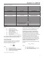
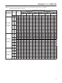
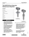
1
Bulletin 71.1:MR105
January 2015
Type MR105 Direct-Operated Pressure
Reducing Regulators
P1205
P1204
TYPE MR105 DIRECT-OPERATED REGULATOR WITH
LOW-PRESSURE ACTUATOR
TYPE MR105 DIRECT-OPERATED REGULATOR WITH
HIGH-PRESSURE ACTUATOR
Contents
Features
Introduction................................................................... 2
• Travel Indicator
• Large Flow
• Stability
• Fast Response
• Steel and Stainless Steel Constructions
Meet API 614 Requirements
• Available Constructions to Meet
NACE MR0175-2003 and NACE MR0103
Requirements for Sour Gas Service Capability
• Multiple Trim Materials Available
• ANSI/FCI 70-3-2004 Class VI Shutoff
• Multiple End Connection Options
• P1 = P2 on High-Pressure Actuator
• Suitable for High-Temperature Applications
up to 250°F / 121°C
• Easy Access to Trim Parts
• Drain Valve
• Pressure-Loaded Actuator
• Bleed valve (for High-Pressure Actuator only)
Specifications............................................................... 2
Features....................................................................... 3
Principle of Operation................................................... 4
Overpressure Protection.............................................. 4
Installation.................................................................... 6
Applications.................................................................. 6
Universal NACE Compliance....................................... 8
Capacity Information.................................................... 8
Ordering Information.................................................. 27
Ordering Guide .......................................................... 27
www.fisherregulators.com
D103256X012
Figure 1. Type MR105 Direct-Operated Pressure Reducing Regulators
Bulletin 71.1:MR105
Specifications
The Specifications section on this page provides the ratings and other specifications for the Type MR105. The
following information is stamped on the nameplate fastened on the regulator at the factory: type; body size;
maximum inlet, outlet and differential pressure; maximum pressure above setpoint; maximum casing pressure;
maximum temperature; spring range; cage type; and trim and diaphragm material.
Body Sizes and End Connection Styles
See Table 1
Downstream Control Line Connection Size 1/2 NPT
Shutoff Classification per ANSI/FCI 70-3-2004
Class VI (Soft Seat)
Maximum Pressure Over Setpoint to Avoid Internal
Parts Damage(1)
Low-Pressure Actuator: 20 psig / 1.4 bar
High-Pressure Actuator: 120 psig / 8.3 bar
Maximum Inlet, Outlet and Emergency Casing
Pressure(1)
See Table 3
Outlet Pressure Ranges
5 to 300 psig / 0.34 to 20.7 bar; see Table 2
(1)
Maximum Setpoint
Low-Pressure Actuator: 43 psig / 3.0 bar
High-Pressure Actuator:
Nitrile (NBR) and Ethylene Propylene (EPDM)
Diaphragm: 300 psig / 20.7 bar
Fluorocarbon (FKM) Diaphragm:
150 psig / 10.3 bar
(1)
Construction Materials
See Table 6
Maximum Differential Pressures(1)
See Table 4
Flow and Sizing Coefficients
See Table 5
Temperature Capabilities(1)
Nitrile (NBR): -20 to 180°F / -29 to 82°C
Fluorocarbon (FKM): 20 to 250°F / -7 to 121°C(2)
Ethylene Propylene (EPDM)(3): -20 to 225°F /
-29 to 107°C
Pressure Registration
External
Spring Case Vent
Type Y602-12
Pressure-Loaded Spring Case Vent Connection
1/2 NPT
Approximate Weights
For Type MR105 with Low-Pressure Actuator
NPS 1 / DN 25: 86 lbs / 39 kg
NPS 2 / DN 50: 116 lbs / 53 kg
NPS 3 / DN 80: 165 lbs / 75 kg
NPS 4 / DN 100: 174 lbs / 79 kg
For Type MR105 with High-Pressure Actuator
NPS 1 / DN 25: 76 lbs / 34 kg
NPS 2 / DN 50: 105 lbs / 48 kg
NPS 3 / DN 80: 155 lbs / 70 kg
NPS 4 / DN 100: 164 lbs / 74 kg
Options
• Visual Travel Indicator
• Drain Valve
• Pressure-Loaded Actuator
• NACE Construction
• Bleed Valve (for High-Pressure Actuator Only)
• Ethylene Propylene (EPDM) Elastomer
Trim Parts
1. The pressure/temperature limits in this Bulletin or any applicable standard limitation should not be exceeded.
2. Fluorocarbon (FKM) is limited to 200°F / 93°C in hot water.
3. Ethylene Propylene (EPDM) is limited to 20 to 250°F / -7 to 121°C when used with Low Pressure Actuator.
Introduction
The Type MR105 regulators are direct-operated, pressure
reducing, high-capacity, multi-purpose regulators.
They are designed to handle pressures up to 400 psig /
27.6 bar and temperatures up to 250°F / 121°C.
This product provides a simple, fast, reliable and
economical way to control and reduce pressure in multipurpose applications suitable for different flow media
such as liquid, air and gas. Applications include lube oil
2
systems and any application where speed of response is
critical, minimum differential pressure is a concern or fluid
is not free of impurities. Type MR105 regulator with a
low-pressure actuator can be set up to 43 psig / 3.0 bar
and the high-pressure actuator version can be set up
to 300 psig / 20.7 bar.
The units are available in 4 sizes, NPS 1 through 4 /
DN 25 through 100 and are available in several
end connection configurations to meet demands on
application requirements.
Bulletin 71.1:MR105
Table 1. Body Sizes and End Connection Styles
END CONNECTION STYLE
Body Size
NPS 1 and 2 / DN 25 and 50
NPS 3 and 4 / DN 80 and 100
BODY MATERIAL
Cast Iron
NPT, CL125 FF, CL250 RF
CL125 FF, CL250 RF
WCC steel(1)(2)
NPT, CL150 RF, CL300 RF, CL600 RF
or PN 16/25/40 RF
CL150 RF, CL300 RF, CL600 RF
or PN 16 RF
CF8M Stainless steel(1)(2)
NPT, CL150 RF, CL300 RF, CL600 RF
or PN 16/25/40 RF
CL150 RF, CL300 RF, CL600 RF
or PN 16 RF
CF3M Stainless steel(1)(2)
NPT, CL150 RF, CL300 RF, CL600 RF
or PN 16/25/40 RF
CL150 RF, CL300 RF, CL600 RF
or PN 16 RF
1. Optional NACE construction available.
2. Constructions meet API 614 requirements.
Table 2. Outlet Pressure Ranges
BODY SIZE, NPS 1 AND 2 / DN 25 AND 50
Actuator Type
Low Pressure
High Pressure
Spring Range
psig
5 to 12
10 to 24
14 to 32
18 to 43
25 to 60(1)
43 to 100
75 to 175(2)
110 to 300(2)
bar
0.34 to 0.83
0.69 to 1.6
0.96 to 2.2
1.2 to 3.0
1.7 to 4.1(1)
3.0 to 6.9
5.2 to 12.1(2)
7.6 to 20.7(2)
Spring Part
Number
Spring Color
Code
GE42909X012
GE42910X012
GE42911X012
GE43002X012
GE42907X012
GE42909X012
GE42910X012
GE42911X012
White
Silver
Orange
Red
Green
White
Silver
Orange
Spring Wire Diameter
In.
0.437
0.500
0.562
0.625
0.375
0.437
0.500
0.562
mm
11.1
12.7
14.3
15.9
9.52
11.1
12.7
14.3
Spring Free Length
In.
9.70
mm
Maximum Pressure
Over Setpoint to Avoid
Internal Parts Damage
psig
bar
20
1.4
120
8.3
246
BODY SIZE, NPS 3 AND 4 / DN 80 AND 100
Actuator Type
Low Pressure
High Pressure
Spring Range
psig
5 to 8
8 to 20
12 to 30
18 to 39
39 to 72
71 to 175(2)
110 to 250(2)
bar
0.34 to 0.55
0.55 to 1.4
0.83 to 2.1
1.2 to 2.7
2.7 to 5.0
4.9 to 12.1(2)
7.6 to 17.2(2)
Spring Part
Number
Spring Color
Code
GE42909X012
GE42910X012
GE42911X012
GE43002X012
GE42909X012
GE42910X012
GE42911X012
White
Silver
Orange
Red
White
Silver
Orange
Spring Wire Diameter
In.
0.437
0.500
0.562
0.625
0.437
0.500
0.562
mm
11.1
12.7
14.3
15.9
11.1
12.7
14.3
Spring Free Length
In.
mm
9.70
246
Maximum Pressure
Over Setpoint to Avoid
Internal Parts Damage
psig
bar
20
1.4
120
8.3
1. NPS 2 / DN 50 body size spring range is limited to 45 psig / 3.1 bar.
2. Maximum setpoint is limited to 150 psig / 10.3 bar for constructions with Fluorocarbon (FKM) diaphragm.
Available in linear and quick opening trim cages for gas
and liquid applications, respectively. The cage-guided
metal plug provides superior control and stability.
Fast Response—Direct-operated allows for fast
response to meet the most demanding pressure and
flow requirements.
The Type MR105 with steel or stainless steel body
construction has been designed to meet API 614 as
required by lube oil manufacturers.
Steel and Stainless Steel Constructions Meet
API 614 Requirements—Steel and Stainless steel
body constructions comply with the recommendations of
API Standard 614.
Features
Available Constructions to Meet
NACE MR0175-2003 and NACE MR0103
Requirements for Sour Gas Service Capability—
Optional materials are available for applications
handling sour gases. These constructions comply
with the recommendations of NACE International
Standards MR0175 and MR0103.
Travel Indicator—Travel indicator option provides
visual indication of the valve movement from the
closed to open position.
Large Flow—Able to pass large flow rates with
minimal offset from setpoint.
Stability—The Type MR105 regulator’s cage-guided
metal plug design provides superior control stability of
delivery pressure.
Multiple Trim Materials Available—416, 316 and
316L Stainless steel options are available to meet
wider application requirements including demands on
lube oil and cooling water applications.
3
Bulletin 71.1:MR105
Table 3. Maximum Inlet, Outlet and Emergency Casing Pressures(1)
BODY
MATERIAL
Cast Iron
WCC steel
CF8M
Stainless steel
CF3M
Stainless steel
END
CONNECTION
NPT
CL125 FF
CL250 RF
NPT
CL150 RF
CL300 RF
CL600 RF
PN 16 RF
PN 16/25/40 RF
NPT
CL150 RF
CL300 RF
CL600 RF
PN 16 RF
PN 16/25/40 RF
NPT
CL150 RF
CL300 RF
CL600 RF
PN 16 RF
PN 16/25/40 RF
MAXIMUM INLET PRESSURE
psig
bar
340
175
400
400
245
23.4
12.1
27.6
27.6
16.9
400
27.6
245
400
400
225
16.9
27.6
27.6
15.5
400
27.6
225
400
400
185
15.5
27.6
27.6
12.7
400
27.6
185
400
12.7
27.6
MAXIMUM OUTLET PRESSURE
Low-Pressure
High-Pressure
Actuator
Actuator(2)
psig
bar
psig
bar
340
23.4
70
4.8
175
12.1
400
27.6
400
27.6
245
16.9
70
70
70
4.8
4.8
4.8
400
27.6
245
400
400
225
16.9
27.6
27.6
15.5
400
27.6
225
400
400
185
15.5
27.6
27.6
12.7
400
27.6
185
400
12.7
27.6
MAXIMUM EMERGENCY CASING
Low-Pressure
High-Pressure
Actuator
Actuator(2)
psig
bar
psig
bar
340
23.4
70
4.8
175
12.1
400
27.6
400
27.6
245
16.9
70
70
70
4.8
4.8
4.8
400
27.6
245
400
400
225
16.9
27.6
27.6
15.5
400
27.6
225
400
400
185
15.5
27.6
27.6
12.7
400
27.6
185
400
12.7
27.6
1. Based on a maximum temperature of 250°F / 121°C.
2. Maximum outlet and emergency casing pressures for constructions with Fluorocarbon (FKM) diaphragm are limited to 230 psig / 15.8 bar or the body rating limit, whichever is lower.
ANSI/FCI 70-3-2004 Class VI Shutoff—Soft-seat
valve plug disks for tight shutoff.
Multiple End Connection Options—Type MR105 is
available in several end connection configurations to
meet demands on application requirements.
P1 = P2 on High-Pressure Actuator—Inlet pressure
rating equals outlet pressure rating on high-pressure
actuator constructions up to 400 psig / 27.6 bar.
Easy Drain—Feature allows you to drain the system
without expensive spool pieces saving you time
and space.
Easy Bleed—Feature allows you to purge the air
trapped underneath the diaphragm when the highpressure regulator is installed in the upright position,
which improves speed of response.
Principle of Operation
Refer to Figure 2. The Type MR105 is a directoperated pressure reducing regulator. Downstream
pressure is registered externally through a 1/2 NPT
control line tapped in the low-pressure actuator bonnet
or in the high-pressure actuator lower casing. When
downstream demand decreases, the pressure under
the actuator diaphragm increases. This pressure
overcomes the regulator setting (which is set by
the regulator control spring). Through the action of
4
the actuator stem and valve spring, the valve plug
moves closer to the seat ring and reduces flow. When
demand downstream increases, pressure under the
actuator diaphragm decreases. Spring force pushes
the actuator stem downward, the valve plug moves
away from the seat ring and the flow increases
downstream as the regulator opens in response to
the decreased pressure underneath the diaphragm.
The downward motion of the plug allows gas to flow
through the cage into the downstream system.
Increased downstream pressure permits the regulator
to close. The combination of valve spring force and
valve plug unbalance provides positive valve plug
shutoff against the port and upper seals.
Overpressure Protection
Type MR105 regulator with the low-pressure actuator
has outlet pressure ratings lower than the inlet
pressure ratings. Complete downstream overpressure
protection is needed if the actual inlet pressure
exceeds the outlet pressure rating.
Overpressuring any portion of a regulator or
associated equipment may cause personal injury,
leakage or property damage due to bursting
of pressure-containing parts or explosion of
accumulated gas. Provide appropriate pressurerelieving or pressure-limiting devices to ensure
Bulletin 71.1:MR105
VALVE SPRING
VALVE PLUG
CAGE
SEAT RING
ACTUATOR STEM
ACTUATOR
DIAPHRAGM
CONTROL SPRING
M1178
TYPE MR105 WITH LOW-PRESSURE ACTUATOR
VALVE SPRING
VALVE PLUG
SEAT RING
CAGE
ACTUATOR STEM
DIAPHRAGM
ACTUATOR
CONTROL SPRING
TYPE MR105 WITH HIGH-PRESSURE ACTUATOR
M1181
INLET PRESSURE
OUTLET PRESSURE
ATMOSPHERIC PRESSURE
INTERMEDIATE PRESSURE
Figure 2. Type MR105 Operational Schematic
5
Bulletin 71.1:MR105
FILTER 2
PUMP 2
TYPE MR105
PRESSURE REDUCING
REGULATOR
TO EQUIPMENT
BEARINGS, SEALS OR
SERVO-CONTROLS
PUMP 1
FILTER 1
OIL TANK
M1202
TYPE MR108
BACKPRESSURE REGULATOR
Figure 3. Lube Oil Skid Diagram
that the limits in the Specifications section are not
exceeded. Regulator operation within ratings does
not prevent the possibility of damage from external
sources or from debris in the pipeline. A regulator
should be inspected for damage periodically and after
any overpressure condition. Refer to the relief sizing
coefficients in the Specifications and the Capacity
Information section to determine the required relief
valve capacity.
Installation
Vertical installation with the actuator installed directly
above or below the main valve is recommended but for
optimal performance the actuator should be installed
below the main valve. The use of a bleed valve is
recommended for liquid installations that require the
high pressure actuator to be mounted above the main
valve. The unit will operate in horizontal installations
with the actuator on the side, however, this could result
in premature wear of parts. Make sure that flow will
be in the same direction as that indicated by the body
arrow. Orientation of the two vents should always be
down. Vents may be rotated after regulator installation
so that the vent screens are down.
A control line must be installed to allow outlet pressure
to register on the actuator’s diaphragm. The size of the
control line is indicated in the Specifications section,
and should be installed four to eight pipe diameter
downstream of the regulator and in an area of pipe that
is free of turbulence.
An instruction manual is provided with every regulator
shipped. Refer to this for detailed installation,
operation, adjustment and maintenance instructions.
Included is a complete listing of individual parts and
recommended spare parts.
6
Applications
Note
A linear cage is recommended for
applications where low flow stability
is a concern but it will limit the overall
capacity of the regulator.
Lube Oil Skids (Figure 3)
Lube oil skids maintain oil flow to bearings, seals and
servo-controls on critical turbomachinery assets such as
air and gas compressors, steam turbines, power recovery
turbines and power generating equipment. These skids
are essential in keeping lube oil clean at all times and
ensure maximum service life for the equipment. Because
it is critical to maintain a constant flow and pressure of
oil to the equipment, it is normally equipped with two
pumps – the main pump and the auxiliary pump, which
will take over in case of main pump failure – and filters.
In normal condition, the skids operate in the
following manner:
• Lube oil is stored in the tank at atmospheric pressure.
• It is then fed to the main pump (Pump 1) which
pressurizes the lube oil.
• Oil then goes through a filter.
• After filtration, oil flow is split such that a fraction
is sent to a backpressure regulator to limit the supply
pressure to the pressure reducing regulator. 20%
of the pump rate flows through the backpressure
regulator, sending back oil to the oil tank.
• The pressure reducing regulator decreases the
pressure to a safe and allowable range. Flow
through this regulator is 80% of pump rate.
Bulletin 71.1:MR105
WORKER CONTROL LINE
SET HIGHER THAN
WORKER REGULATOR
MONITOR CONTROL LINE
TYPE MR105
MONITOR REGULATOR
M1203
TYPE MR105
WORKER REGULATOR
INLET PRESSURE
OUTLET
PRESSURE
INLET
PRESSURE
ATMOSPHERIC PRESSURE
OUTLET
PRESSURE
INTERMEDIATE
PRESSURE
ATMOSPHERIC PRESSURE
INTERMEDIATE PRESSURE
Figure 4. Type MR105 Monitor Regulator Operational Schematic
• Oil flows to large rotating equipment lubricating
bearings, e.g. turbines and compressors.
The loss of pressure or flow to the bearings or these
turbomachinery assets may shut down the equipment or
even the whole plant. Failure of the main pump or filter
results in the following upset operation:
• Auxiliary pump (Pump 2) and filter system is
brought into operation while main pump is
in operation.
• Auxiliary pump ramp up rate is one second.
• Auxiliary pump produces a pressure spike
that is beyond the limitations of the pressure
reducing regulator.
• The backpressure regulator relieves the excess
pressure back to the oil tank. Flow rate is 120% of
total pump rate.
Main pump can now be shut down to allow repair of
the system. High capacity direct-operated regulators
are recommended for this type of application where
speed of response is critical. The Type MR105 can
provide fast response to the pressure spikes as
described above while maintaining a constant delivery
pressure of oil to the bearing.
Wide-Open Monitoring System
Refer to Figure 4. Monitoring system provides
overpressure protection by containment and therefore
does not vent to the atmosphere. It involves a specific
arrangement of two regulators in series which are
configured such that if one regulator fails wide open,
the other regulator assumes control to maintain
the downstream pressure at a set limit. During an
overpressure situation, monitoring systems keep the
customer on line. Testing is also relatively easy. To
perform a periodic test on a monitoring regulator, increase
the outlet set pressure of the worker regulator and watch
the outlet pressure gauge to determine if the monitor
regulator takes over at the appropriate outlet pressure.
In such systems, both regulators are sensing downstream
pressure. During normal operation of a wide-open monitor
configuration, one regulator (worker) is set at the desired
downstream pressure. The other regulator (monitor) is set
at a higher pressure and remains wide open. The lock-up
pressure will be the worker regulator lock-up pressure.
If the worker regulator fails open, the monitor regulator
controls the downstream pressure at its setpoint and the
lock-up pressure will be the monitor lock-up pressure.
7
Bulletin 71.1:MR105
Table 4. Maximum Differential Pressures
ACTUATOR TYPE
Low Pressure
High Pressure
MAXIMUM DIFFERENTIAL PRESSURE
Gas Service (Linear Cage)
Liquid Service (Quick Opening Cage)
psid
bar d
psid
bar d
200
13.6
400 or maximum
27.6 or maximum
200
13.6
inlet pressure,
inlet pressure,
225
15.5
whichever is lower
whichever is lower
225
15.5
250
17.2
400 or maximum
27.6 or maximum
200
13.6
inlet pressure,
inlet pressure,
225
15.5
whichever is lower
whichever is lower
250
17.2
BODY SIZE
NPS
1
2
3
4
1
2
3
4
DN
25
50
80
100
25
50
80
100
Table 5. Wide-Open Flow and IEC Sizing Coefficients
Body Size
NPS
1
2
3
4
DN
25
50
80
100
Body Size
NPS
1
2
3
4
DN
25
50
80
100
Body Size
NPS
2
DN
50
LINEAR CAGE
Wide-Open Flow Coefficient
Line Size Equals Body Size
Cg
Cv
463
13.7
761
22.5
997
30.5
934
27.5
Wide-Open Flow Coefficient
Line Size Equals Body Size
Cg
Cv
597
17.5
1740
48.2
3540
103.1
4300
135.9
Wide-Open Flow Coefficient
Line Size Equals Body Size
Cg
Cv
1570
43.8
C1
IEC Sizing Coefficient
Km
34.0
0.81
33.8
0.75
32.7
0.78
34.0
0.77
QUICK OPENING CAGE
C1
FL
XT
Fd
0.90
0.87
0.88
0.88
0.73
0.72
0.68
0.75
0.36
0.24
0.22
0.18
IEC Sizing Coefficient
Km
FL
34.1
0.81
0.90
36.1
0.81
0.90
34.4
0.76
0.87
31.6
0.72
0.85
REDUCED PORT QUICK OPENING CAGE
IEC Sizing Coefficient
XT
Fd
0.73
0.82
0.75
0.65
0.43
0.34
0.32
0.30
C1
Km
FL
XT
Fd
35.9
0.81
0.90
0.72
0.36
Universal NACE Compliance
For Critical Pressure Drops
Optional materials are available for applications
handling sour gases. These constructions comply with
the recommendations of NACE International Sour
Service Standards.
Use this equation for critical pressure drops (absolute
outlet pressure equal to one-half or less than one-half
the absolute inlet pressure).
The manufacturing processes and materials used
by Emerson Process Management Regulator
Technologies, Inc. assure that all products specified
for sour gas service comply with the chemical,
physical and metallurgical requirements of NACE
MR0175 and/or NACE MR0103. Customers have
the responsibility to specify correct materials.
Environmental limitations may apply and shall be
determined by the user.
Capacity Information
Air Capacities
To determine wide-open flow capacity for relief valve
sizing, use one of the following equations:
8
Q = P1(abs)Cg
where,
Q = gas flow rate, SCFH
Cg = gas sizing coefficient
P1 = absolute inlet pressure, psia
For Non-Critical Pressure Drops
Use this equation for pressure drops lower than critical
(absolute outlet pressure greater than one-half of
absolute inlet pressure).
Q=
520
3417 ΔP
C P SIN
DEG
GT g 1
C1
P1
Bulletin 71.1:MR105
Table 6. Construction Materials
PART NAME
STANDARD
OPTIONAL
Body
WCC steel(1)
Cast Iron, CF8M, CF3M Stainless steel
Body Flange
WCC steel(1)
CF8M, CF3M Stainless steel
Actuator Casings - Low Pressure
AISI 1010 steel(1)
316/316L Stainless steel
Actuator Casings - High Pressure
WCC steel(1)
CF3M/CF8M Stainless steel
Internal Stiffener Plate
AISI 1010 steel(1)
316/316L Stainless steel
Spring Case
WCC steel
CF3M/CF8M Stainless steel
Spring Case Spacer
Zinc-Plated steel
Stainless steel
Cage
CF3M/CF8M (Quick Opening), CF8M (Linear) Stainless Steel
Valve Plug and Seat Ring
316, 316L,
S20910 (Nitronic 50) Stainless steel
(NPS 1 / DN 25 body size only)
416 Stainless steel
Closing Spring
Inconel® X750
Stem
S17400 H1075 Stainless steel
Lower Diaphragm Support
S20910 (Nitronic 50) Stainless steel
S17400 H1075 Stainless steel
Diaphragm and Seals
Nitrile (NBR)
Fluorocarbon (FKM), Ethylene Propylene (EPDM)
Upper Diaphragm Plate
Cast Iron
Control/Set Spring
Steel Alloy(1)
Spring Seats
Zinc-Plated steel
Bolting
SA194 Grade B7/NCF (Body to Bonnet),
SAE Grade 5/NCF (Actuator)
Stainless steel
Adjusting Screw
Zinc-Plated steel
Stainless steel
1. Powder coated.
where,
Maximum Allowable Pressure Drop for Liquid
Q = gas flow rate, SCFH
G = specific gravity of the gas
T =absolute temperature of gas
at inlet, °Rankine
Cg = gas sizing coefficient
P1 = absolute inlet pressure, psia
C1 = flow coefficient
ΔP = pressure drop across the regulator, psi
Pressure drops in excess of allowable will result in
choked flow and possible cavitation damage.
Then, if capacity is desired in normal cubic meters per hour
at 0°C and 1.01325 bar, multiply SCFH by 0.0268.
Cavitation and flashing are physical changes in the
process fluid. The change is from the liquid state to
the vapor state and results from the increase in fluid
velocity at or just downstream of the greatest flow
restriction, normally the regulator orifice.
Liquid Capacities
To determine regulating capacities or to determine
wide-open capacities for relief sizing at any inlet
pressure, use the following equation.
Q = Cv
ΔP
G
where,
Q =
ΔP =
CV =
G =
liquid flow rate, GPM
pressure drop across the regulator, psi
regulating or wide-open flow coefficient
specific gravity of the liquid
Choked flow is the formation of vapor bubbles in
the liquid flowstream causing a condition at the
vena contracta which tends to limit flow through
the regulator. The vena contracta is the minimum
cross-sectional area of the flow stream occurring just
downstream of the actual physical restriction.
To determine the maximum allowable pressure drop
for water:
ΔP(allow) = Km (P1)
where,
ΔP = Valve differential in psi
Km = Valve recovery coefficient from Table 5
P1 = Valve inlet pressure in psia
Inconel® is a mark owned by Special Metals Corporation.
9
Bulletin 71.1:MR105
Table 7. Typical Air CV Coefficient with Linear Cage - Setpoint Made at 10% Flow (for Type MR105 with Low-Pressure Actuator)
SPRING RANGE,
PART NUMBER
AND COLOR
5 to 12 psig /
0.34 to 0.83 bar
GE42909X012
White
SET
PRESSURE
INLET
PRESSURE
psig
bar
psig
25
5
0.34
10
10
10 to 24 psig /
0.69 to 1.6 bar
GE42910X012
Silver
15
20
15
14 to 32 psig /
0.96 to 2.2 bar
GE42911X012
Orange
20
25
30
18 to 43 psig /
1.2 to 3.0 bar
GE43002X012
Red
0.69
0.69
1.0
1.4
1.0
1.4
1.7
2.1
20
1.4
25
1.7
30
35
40
2.1
2.4
2.8
CV AT % DROOP
bar
1.7
10%
2.58
NPS 1 / DN 25 Body
20%
3.69
10%
2.97
NPS 2 / DN 50 Body
20%
4.52
40%
9.08
75
5.2
2.55
4.02
8.50
3.52
4.50
9.04
150
10.3
2.78
3.98
8.95
3.24
4.97
10.3
250
17.2
2.05
3.24
8.50
3.14
4.81
10.5
25
1.7
2.56
6.04
13.6
4.66
9.56
20.3
75
5.2
3.96
7.72
13.7
4.63
8.68
21.9
150
10.3
3.64
6.80
13.7
3.89
8.39
21.8
250
17.2
3.84
8.45
13.7
4.34
8.26
20.4
25
1.7
2.57
4.88
10.9
3.75
6.47
13.1
75
5.2
2.82
5.05
11.3
3.38
6.06
12.8
150
10.3
2.80
5.01
11.6
3.56
6.15
14.3
250
17.2
3.25
5.12
12.7
3.46
6.48
14.3
25
1.7
3.67
7.36
13.7
4.64
9.99
21.6
75
5.2
3.81
7.38
13.7
5.03
9.36
22.1
150
10.3
3.91
7.77
13.7
5.13
9.84
22.1
250
17.2
3.84
7.85
13.7
4.53
9.84
21.5
50
3.4
4.68
10.4
13.7
5.98
12.3
22.5
75
5.2
4.48
9.64
13.7
5.71
11.9
22.5
150
10.3
4.76
11.0
13.7
4.83
10.5
22.5
250
17.2
4.89
10.1
13.7
5.92
13.6
22.5
25
1.7
2.95
5.58
12.1
4.27
7.34
16.5
75
5.2
2.81
5.54
12.1
3.67
6.49
15.4
150
10.3
2.86
5.18
11.7
4.05
7.50
16.4
250
17.2
3.01
5.77
13.3
3.87
7.08
18.3
25
1.7
3.87
7.67
13.2
4.77
10.4
19.8
75
5.2
3.42
6.69
13.7
4.51
8.77
21.9
150
10.3
3.52
6.99
13.7
5.15
9.67
22.0
250
17.2
3.73
7.26
13.7
4.34
8.94
21.8
50
3.4
4.68
9.18
13.7
5.12
11.1
22.3
75
5.2
3.73
8.46
13.7
4.83
11.9
22.3
150
10.3
4.05
8.79
13.7
5.2
11.4
22.5
250
17.2
4.06
9.73
13.7
4.78
10.9
22.5
50
3.4
5.18
11.1
13.7
5.77
13.8
22.3
75
5.2
4.99
11.2
13.7
6.33
14.1
22.5
150
10.3
4.78
11.1
13.7
6.23
14.5
22.4
250
17.2
5.53
12.7
13.7
5.29
13.6
22.5
50
3.4
2.69
5.46
11.2
3.74
7.43
15.5
75
5.2
2.59
5.13
11.1
4.66
6.60
15.3
150
250
50
10.3
17.2
3.4
3.03
2.83
3.18
5.36
5.03
6.49
11.9
12.0
13.0
4.19
4.06
4.97
7.44
7.00
8.82
16.2
16.8
20.4
75
5.2
3.67
6.90
13.7
4.11
8.98
20.6
150
10.3
3.22
6.73
13.7
4.80
8.97
21.0
250
17.2
3.46
6.66
13.7
4.59
8.76
20.3
50
3.4
4.41
8.24
13.7
4.77
10.9
21.5
75
5.2
4.18
8.24
13.7
5.82
10.2
22.1
150
10.3
3.96
8.30
13.7
5.89
10.9
22.0
250
17.2
3.79
7.89
13.7
5.04
10.7
22.1
50
3.4
4.70
9.42
13.7
5.93
12.5
21.9
75
5.2
4.64
9.11
13.7
6.19
13.1
22.3
150
10.3
4.44
9.42
13.7
6.28
12.9
22.4
250
17.2
4.41
9.14
13.7
5.69
12.5
22.5
50
3.4
5.34
11.1
13.7
6.31
15.2
21.7
75
5.2
4.55
10.5
13.7
7.17
14.8
22.1
150
10.3
4.52
11.0
13.7
5.53
12.1
22.5
250
17.2
5.11
11.0
13.7
6.29
14.9
22.5
- continued 10
40%
7.51
Bulletin 71.1:MR105
Table 7. Typical Air CV Coefficient with Linear Cage - Setpoint Made at 10% Flow (for Type MR105
with Low-Pressure Actuator) (continued)
SPRING RANGE,
PART NUMBER
AND COLOR
5 to 8 psig /
0.34 to 0.55 bar
GE42909X012
White
8 to 20 psig /
0.55 to 1.4 bar
GE42910X012
Silver
12 to 30 psig /
0.83 to 2.1 bar
GE42911X012
Orange
18 to 39 psig /
1.2 to 2.7 bar
GE43002X012
Red
SET
PRESSURE
INLET
PRESSURE
psig
bar
5
0.34
8
0.55
10
0.69
15
1.0
20
1.4
15
1.0
20
1.4
25
1.7
30
2.1
20
1.4
25
1.6
30
2.1
35
2.4
psig
25
75
150
250
25
75
150
250
25
75
150
250
25
75
150
250
50
75
150
250
25
75
150
250
25
75
150
250
50
75
150
250
50
75
150
250
50
75
150
250
50
75
150
250
50
75
150
250
50
75
150
250
bar
1.7
5.2
10.3
17.2
1.7
5.2
10.3
17.2
1.7
5.2
10.3
17.2
1.7
5.2
10.3
17.2
3.4
5.2
10.3
17.2
1.7
5.2
10.3
17.2
1.7
5.2
10.3
17.2
3.4
5.2
10.3
17.2
3.4
5.2
10.3
17.2
3.4
5.2
10.3
17.2
3.4
5.2
10.3
17.2
3.4
5.2
10.3
17.2
3.4
5.2
10.3
17.2
CV AT % DROOP
10%
4.96
4.63
4.43
3.97
6.47
5.72
5.22
5.50
5.54
5.79
5.28
5.18
7.06
7.06
6.33
6.68
6.51
8.53
8.19
8.41
5.84
5.71
5.39
5.51
7.94
6.68
6.36
5.72
9.28
7.34
5.83
8.30
9.98
10.3
8.45
8.39
5.86
5.77
5.46
5.89
7.28
6.87
5.26
6.59
6.57
8.02
7.09
7.25
10.6
7.36
7.05
7.89
NPS 3 / DN 80 Body
20%
6.90
6.63
6.60
5.81
10.5
9.35
8.82
9.05
9.22
8.79
8.07
8.34
13.2
12.9
11.9
12.3
13.7
16.8
16.7
16.8
9.95
9.19
9.13
9.10
14.2
12.0
11.4
10.9
15.8
14.6
12.4
15.9
17.3
19.6
16.8
18.2
9.73
9.40
9.05
9.60
12.7
12.1
9.59
11.6
13.0
14.6
13.6
13.5
17.5
14.8
14.5
16.0
40%
12.2
12.2
11.3
11.1
21.7
20.2
19.1
20.1
17.6
17.3
16.9
17.4
29.1
29.1
28.0
27.7
30.5
30.5
30.5
30.5
20.4
19.9
19.5
19.9
28.1
27.7
27.6
26.9
30.5
30.5
30.5
30.5
30.5
30.5
30.5
30.5
20.3
20.6
19.9
20.4
26.5
27.1
23.1
26.7
30.5
30.2
29.7
30.5
30.5
30.5
30.5
30.5
10%
4.72
4.47
4.24
4.39
5.58
5.23
5.32
4.55
4.08
4.75
4.58
4.13
5.78
6.06
5.45
5.28
7.20
7.75
6.71
8.00
4.79
5.00
5.10
5.05
5.15
6.54
6.20
5.37
6.78
6.60
6.76
6.30
7.54
8.23
7.94
7.87
4.63
4.94
5.00
5.30
6.02
6.06
6.02
5.67
6.42
6.64
6.49
6.87
7.45
7.97
7.27
7.25
NPS 4 / DN 100 Body
20%
6.55
6.02
6.06
5.97
8.64
8.25
9.08
7.95
7.67
7.29
6.95
6.69
11.0
10.6
9.91
9.73
13.7
13.9
13.1
13.2
7.80
8.10
8.29
8.28
9.96
11.2
10.8
9.58
12.8
13.3
13.0
12.3
16.3
16.7
16.1
16.0
7.98
8.54
8.25
8.59
10.3
10.4
10.3
10.2
11.9
12.1
12.2
12.5
14.2
15.2
14.3
15.0
40%
10.0
10.6
10.8
10.6
17.5
16.8
17.1
17.2
15.0
15.1
13.8
13.9
23.9
23.3
23.0
23.0
25.3
24.8
27.1
27.4
17.0
16.3
17.1
17.2
22.6
24.5
24.4
22.7
25.3
25.2
25.3
25.5
25.1
25.2
25.2
25.4
16.7
16.8
17.1
18.0
22.8
22.4
23.3
23.5
25.8
26.1
25.5
26.8
26.3
26.3
26.6
26.7
11
Bulletin 71.1:MR105
Table 8. Typical Air CV Coefficient with Linear Cage - Setpoint Made at 10% Flow (for Type MR105 with High-Pressure Actuator)
SET
PRESSURE
INLET
PRESSURE
psig
bar
25
1.7
30
2.1
40
2.8
50
3.4
60
4.1
25
1.7
30
2.1
40
2.8
45
3.1
50
3.4
43 to 100 psig /
3.0 to 6.9 bar
60
4.1
GE42909X012
White
75
5.2
100
6.9
75
5.2
100
6.9
125
8.6
150
10.3
175
12.1
125
8.6
150
10.3
200
13.8
250
17.2
300
20.7
psig
50
75
150
250
50
75
150
250
50
75
150
250
75
150
250
75
150
250
50
75
150
250
50
75
150
250
50
75
150
250
75
150
250
75
150
250
75
150
250
100
150
250
150
250
100
250
150
250
200
300
200
300
200
300
150
250
200
300
250
300
300
350
350
SPRING RANGE,
PART NUMBER
AND COLOR
25 to 60 psig /
1.7 to 4.1 bar
GE42907X012
Green
25 to 45 psig /
1.7 to 3.1 bar
GE42907X012
Green
75 to 175 psig /
5.2 to 12.1 bar
GE42910X012
Silver
110 to 300 psig /
7.6 to 20.7 bar
GE42911X012
Orange
bar
3.4
5.2
10.3
17.2
3.4
5.2
10.3
17.2
3.4
5.2
10.3
17.2
5.2
10.3
17.2
5.2
10.3
17.2
3.4
5.2
10.3
17.2
3.4
5.2
10.3
17.2
3.4
5.2
10.3
17.2
5.2
10.3
17.2
5.2
10.3
17.2
5.2
10.3
17.2
6.9
10.3
17.2
10.3
17.2
6.9
17.2
10.3
17.2
13.8
20.7
13.8
20.7
13.8
20.7
10.3
17.2
13.8
20.7
17.2
20.7
20.7
24.1
24.1
CV AT % DROOP
10%
2.01
2.10
2.17
2.00
2.17
2.73
2.33
2.28
2.48
2.82
2.50
2.72
2.77
3.01
3.07
3.10
3.62
3.50
2.48
2.61
2.49
2.71
2.77
2.75
2.71
3.33
3.15
3.64
3.57
2.60
2.59
2.71
3.00
3.34
3.50
3.94
3.90
4.06
4.55
2.38
2.94
2.97
3.08
3.82
4.23
3.90
5.06
5.11
NPS 1 / DN 25 Body
20%
2.74
3.13
3.24
2.99
3.47
3.64
3.66
3.72
4.14
4.64
4.34
4.89
5.11
5.55
6.03
5.69
6.83
7.21
4.05
4.12
4.07
4.63
4.85
5.01
5.21
6.23
5.93
7.53
7.50
4.35
4.17
5.14
5.46
6.50
6.63
7.93
8.06
8.86
9.82
4.55
5.07
5.58
5.85
7.75
8.35
9.76
10.2
11.5
- Spring range is not available for the body size.
- continued 12
40%
5.26
5.83
6.30
7.61
6.61
7.13
8.14
10.1
8.86
9.73
10.6
13.6
11.6
13.6
13.7
13.7
13.7
13.7
8.07
9.19
10.8
10.1
10.9
13.3
12.2
13.7
13.7
13.7
13.7
9.01
9.72
11.5
12.7
13.7
13.7
13.7
13.7
13.7
13.7
9.87
11.2
12.7
13.6
13.7
13.7
13.7
13.7
13.7
10%
NPS 2 / DN 50 Body
20%
40%
3.17
2.74
3.18
2.95
2.96
3.37
3.30
3.09
3.41
3.86
3.44
3.60
3.71
3.67
3.92
3.46
3.35
3.30
3.75
3.71
3.69
4.21
4.24
3.89
4.16
4.37
3.50
3.76
3.62
4.17
4.13
4.45
4.90
4.98
5.34
5.70
3.52
3.86
4.10
4.37
4.94
5.62
5.66
6.75
6.56
4.27
3.77
4.01
3.89
4.15
4.44
4.62
4.35
5.39
5.66
5.31
5.46
5.86
5.63
6.01
5.05
4.99
5.12
5.94
5.75
5.81
6.84
7.29
6.84
8.26
8.73
5.02
5.63
6.13
6.72
7.88
8.13
9.21
9.43
11.0
11.3
5.89
6.56
7.14
7.33
9.20
10.5
11.4
13.7
14.2
6.43
6.24
6.81
6.64
7.35
8.00
8.10
7.74
9.80
10.8
10.5
10.4
11.6
11.3
12.4
9.51
9.34
9.71
11.6
11.3
11.7
14.9
15.4
14.8
20.0
21.0
9.72
10.1
13.2
14.2
17.7
18.5
21.8
21.8
22.1
22.5
12.3
12.9
15.3
16.3
21.3
22.1
22.5
22.5
22.5
Bulletin 71.1:MR105
Table 8. Typical Air CV Coefficient with Linear Cage - Setpoint Made at 10% Flow (for Type MR105
with High-Pressure Actuator) (continued)
SET
PRESSURE
INLET
PRESSURE
psig
bar
40
2.8
39 to 72 psig /
2.7 to 5.0 bar
50
3.4
GE42909X012
White
60
4.1
70
4.8
75
5.2
100
6.9
125
8.6
150
10.3
175
12.1
psig
75
150
250
75
150
250
75
150
250
100
150
250
100
150
250
150
250
200
300
200
300
200
300
150
250
200
300
250
300
300
350
SPRING RANGE,
PART NUMBER
AND COLOR
71 to 175 psig /
4.9 to 12.1 bar
GE42910X012
Silver
125
8.6
110 to 250 psig /
7.6 to 17.2 bar
150
10.3
GE42911X012
Orange
200
13.8
250
17.2
bar
5.2
10.3
17.2
5.2
10.3
17.2
5.2
10.3
17.2
6.9
10.3
17.2
6.9
10.3
17.2
10.3
17.2
13.8
20.7
13.8
20.7
13.8
20.7
10.3
17.2
13.8
20.7
17.2
20.7
20.7
24.1
CV AT % DROOP
10%
3.57
4.00
3.87
4.00
3.91
3.89
4.35
3.96
4.54
4.24
4.52
4.51
4.22
4.53
4.30
3.56
4.76
5.49
5.36
5.80
5.91
4.86
6.86
4.40
4.56
5.08
4.16
6.42
6.83
7.58
8.40
NPS 3 / DN 80 Body
20%
4.93
5.45
5.22
5.46
5.49
5.50
6.74
6.06
6.52
6.85
7.11
6.90
6.23
6.56
6.21
6.26
7.42
9.09
8.78
10.3
10.3
9.89
12.4
7.06
6.81
8.27
7.07
11.1
11.5
13.5
15.1
40%
7.96
8.86
8.48
9.98
10.0
9.74
12.4
11.8
12.3
14.0
14.0
14.0
11.4
11.8
11.0
13.4
14.5
19.5
18.7
23.4
22.7
26.3
28.4
14.3
13.5
17.4
15.2
24.4
25.1
29.6
29.5
10%
3.48
3.82
3.68
3.93
3.75
3.70
4.30
3.82
4.32
4.17
4.38
4.30
4.16
4.39
4.11
3.49
4.58
5.37
5.16
5.71
5.72
4.82
6.68
4.35
4.41
5.00
4.03
6.33
6.69
7.49
8.24
NPS 4 / DN 100 Body
20%
4.79
5.20
4.97
5.34
5.25
5.24
6.63
5.82
6.21
6.71
6.86
6.57
6.11
6.35
5.92
6.11
7.11
8.84
8.42
10.1
9.97
9.74
12.0
6.95
6.57
8.10
6.82
10.9
11.2
13.3
14.7
40%
7.68
8.44
8.08
9.68
9.57
9.28
12.1
11.3
11.7
13.6
13.4
13.4
11.0
11.4
10.5
13.0
13.8
18.8
17.8
22.7
21.7
25.6
27.3
13.9
12.9
16.9
14.6
23.7
24.3
27.5
27.5
13
Bulletin 71.1:MR105
Table 9. Typical Water CV Coefficient with Quick Opening Cage - Setpoint Made at 10% Flow (for Type MR105
with Low-Pressure Actuator)
SPRING RANGE,
PART NUMBER
AND COLOR
5 to 12 psig /
0.34 to 0.83 bar
GE42909X012
White
SET
PRESSURE
psig
5
10
10
10 to 24 psig /
0.69 to 1.6 bar
GE42910X012
Silver
15
20
15
14 to 32 psig /
0.96 to 2.2 bar
GE42911X012
Orange
20
25
30
20
25
18 to 43 psig /
1.2 to 3.0 bar
GE43002X012
Red
30
35
40
bar
0.34
0.69
0.69
1.0
1.4
1.0
1.4
1.7
2.1
1.4
1.7
2.1
2.4
2.8
INLET
PRESSURE
CV AT % DROOP
NPS 1 / DN 25 Body
NPS 2 / DN 50 Body
psig
bar
10%
20%
40%
10%
20%
40%
10%
20%
40%
25
1.7
5.30
10.9
17.5
8.17
14.3
24.6
11.9
22.7
39.5
75
5.2
5.00
10.5
17.5
8.81
14.3
21.5
11.0
21.2
33.2
150
10.3
4.51
9.86
16.8
8.59
12.4
17.4
11.5
19.0
31.8
25
1.7
8.75
17.1
17.5
12.5
23.2
42.9
18.3
37.5
48.2
75
5.2
9.11
17.5
17.5
12.2
20.6
35.5
17.8
31.4
48.2
150
10.3
9.45
16.9
17.5
11.9
17.1
29.8
16.9
26.8
44.2
25
1.7
7.25
14.6
17.5
10.0
18.8
33.1
15.3
30.0
48.2
75
5.2
6.52
14.0
17.5
10.3
17.4
28.6
14.6
25.8
41.5
150
10.3
6.68
14.5
17.5
9.71
14.9
24.1
14.7
24.0
36.3
25
1.7
10.9
17.5
17.5
13.6
28.5
43.8
20.9
44.0
48.2
75
5.2
8.29
16.0
17.5
14.2
26.7
42.6
18.1
33.9
48.2
150
10.3
8.33
16.8
17.5
12.2
20.1
33.9
17.3
30.8
48.2
50
3.4
9.90
17.5
17.5
14.8
30.2
43.8
23.3
44.4
48.2
75
5.2
10.7
17.5
17.5
15.9
29.1
43.8
22.3
42.6
48.2
150
10.3
11.4
17.5
17.5
13.7
25.7
43.2
19.5
37.8
48.2
25
1.7
7.08
15.2
17.5
10.6
20.2
36.7
15.6
33.5
48.2
75
5.2
7.65
15.0
17.5
11.2
19.2
33.1
15.7
28.8
47.8
150
10.3
7.11
14.7
17.5
10.7
16.8
28.1
14.8
26.9
46.5
25
1.7
9.07
17.5
17.5
14.0
31.2
43.8
20.0
47.0
48.2
75
5.2
9.93
17.3
17.5
14.3
27.1
43.3
19.9
40.1
48.2
150
10.3
9.40
17.1
17.5
12.3
21.0
36.3
19.3
38.4
48.2
50
3.4
9.53
17.5
17.5
16.6
33.2
43.8
24.2
47.2
48.2
75
5.2
12.4
17.5
17.5
16.3
32.4
43.8
22.1
42.1
48.2
150
10.3
9.92
17.5
17.5
14.0
25.6
43.8
20.3
39.9
48.2
50
3.4
11.7
17.5
17.5
16.7
34.7
43.8
25.0
48.2
48.2
75
5.2
11.8
17.5
17.5
17.6
33.9
43.8
23.7
47.1
48.2
150
10.3
11.8
17.5
17.5
15.5
29.3
43.8
22.0
40.8
48.2
50
3.4
6.89
14.4
17.5
10.8
20.3
35.2
15.9
29.8
48.2
75
5.2
7.55
14.9
17.5
11.3
19.6
34.1
15.9
29.4
48.2
150
10.3
6.88
14.4
17.5
11.0
18.2
29.5
15.7
28.2
44.9
50
3.4
8.77
16.4
17.5
12.8
26.0
43.8
19.1
39.6
48.2
75
5.2
8.28
16.8
17.5
13.5
24.4
41.6
19.0
35.8
48.2
150
10.3
8.86
16.8
17.5
12.0
19.5
33.3
18.2
32.4
48.2
50
3.4
9.80
17.5
17.5
14.4
30.0
43.8
22.7
46.8
48.2
75
5.2
9.53
17.5
17.5
15.0
27.7
43.8
20.5
39.2
48.2
150
10.3
10.5
17.5
17.5
12.8
22.6
39.5
19.4
38.3
48.2
50
3.4
10.2
17.5
17.5
17.0
34.6
43.8
25.1
48.2
48.2
75
5.2
10.3
17.5
17.5
16.8
31.6
43.8
23.7
45.6
48.2
150
10.3
11.5
17.5
17.5
14.1
26.3
43.8
21.8
40.6
48.2
50
3.4
10.7
17.5
17.5
17.4
38.6
43.8
25.1
48.2
48.2
75
5.2
11.2
17.5
17.5
18.9
35.3
43.8
25.3
48.2
48.2
150
10.3
12.2
17.5
17.5
15.5
29.9
43.8
24.3
44.3
48.2
- continued -
14
NPS 2 / DN 50 - Reduced Port
Bulletin 71.1:MR105
Table 9. Typical Water CV Coefficient with Quick Opening Cage - Setpoint Made at 10% Flow (for Type MR105
with Low-Pressure Actuator) (continued)
SPRING RANGE,
PART NUMBER
AND COLOR
5 to 8 psig /
0.34 to 0.55 bar
GE42909X012
White
SET
PRESSURE
psig
5
8
10
8 to 20 psig /
0.55 to 1.4 bar
0.34
0.55
0.69
NPS 4 / DN 100 Body
psig
bar
10%
20%
40%
10%
20%
40%
25
1.7
19.2
32.7
55.3
24.3
44.4
75.2
75
5.2
17.4
27.8
43.0
23.8
38.0
61.1
150
10.3
17.3
22.6
37.2
24.2
34.8
49.5
25
1.7
23.5
46.1
80.5
28.7
65.4
113
75
5.2
21.6
36.8
61.9
29.7
52.1
86.9
150
10.3
19.9
29.3
50.3
27.2
44.8
71.0
25
1.7
22.5
43.2
75.3
29.8
57.5
100
75
5.2
20.9
35.6
62.6
28.9
50.6
84.4
150
10.3
20.4
31.6
51.9
27.8
43.5
71.7
25
1.7
29.8
62.4
103
36.9
82.1
136
75
5.2
27.7
51.3
85.0
33.7
71.0
124
10.3
23.2
40.9
72.2
35.0
58.9
99.9
50
3.4
32.9
68.7
103
40.8
92.5
136
75
5.2
30.6
64.7
103
40.3
86.8
136
150
10.3
28.3
51.6
91.2
38.4
70.1
127
25
1.7
25.4
50.4
91.1
30.7
64.5
119
75
5.2
23.6
42.2
72.7
28.4
55.2
94.8
150
10.3
21.5
36.0
62.1
29.5
51.0
83.1
25
1.7
30.6
70.3
103
38.6
91.0
136
75
5.2
28.0
54.6
94.0
34.6
68.1
124
12 to 30 psig /
0.83 to 2.1 bar
150
10.3
23.8
43.6
77.6
35.4
62.4
103
50
3.4
32.6
67.4
103
42.9
90.1
136
GE42911X012
Orange
75
5.2
32.6
66.0
103
39.9
82.8
136
150
10.3
28.9
54.9
92.3
39.4
73.7
126
250
17.2
27.1
46.8
79.3
36.0
61.3
106.9
50
3.4
38.2
81.7
103
47.1
107
136
75
5.2
38.4
76.8
103
46.5
98.2
136
150
10.3
32.5
64.1
103
43.8
86.0
136
250
17.2
29.6
52.6
84.3
40.8
73.2
124.2
50
3.4
24.6
46.3
80.3
30.6
57.4
105
75
5.2
24.1
43.8
77.1
29.7
57.0
99.8
150
10.3
21.8
38.1
65.0
29.0
50.2
87.2
50
3.4
28.4
56.4
103
36.4
70.1
127
75
5.2
29.5
54.2
94.0
32.9
68.2
121
150
10.3
24.0
45.4
78.8
33.2
61.1
104
18 to 39 psig /
1.2 to 2.7 bar
250
17.2
23.9
39.9
66.1
31.9
53.8
91.0
GE43002X012
Red
50
3.4
31.7
65.8
103
38.8
83.4
136
75
5.2
32.5
64.2
103
37.2
79.0
136
150
10.3
27.5
54.9
92.8
36.0
71.0
121
250
17.2
25.6
45.4
79.0
34.7
60.9
106.3
50
3.4
36.0
77.2
103
42.8
99.4
136
75
5.2
37.0
74.6
103
41.1
88.9
136
150
10.3
31.1
61.8
103
38.7
80.4
136
250
17.2
28.7
52.4
88.5
39.5
71.3
122
20
15
20
25
30
20
25
30
35
1.0
NPS 3 / DN 80 Body
150
GE42910X012
Silver
15
bar
CV AT % DROOP
INLET
PRESSURE
1.4
1.0
1.4
1.7
2.1
1.4
1.7
2.1
2.4
15
Bulletin 71.1:MR105
Table 10. Typical Water CV Coefficient with Quick Opening Cage - Setpoint Made at 10% Flow (for Type MR105
with High-Pressure Actuator)
SET
PRESSURE
INLET
PRESSURE
psig
bar
25
1.7
30
2.1
40
2.8
50
3.4
60
4.1
25
1.7
25 to 45 psig /
1.7 to 3.1 bar
30
2.1
GE42907X012
Green
40
2.8
45
3.1
50
3.4
43 to 100 psig /
3.0 to 6.9 bar
60
4.1
GE42909X012
White
75
5.2
100
6.9
75
5.2
100
6.9
125
8.6
150
10.3
175
12.1
125
8.6
110 to 300 psig /
7.6 to 20.7 bar
150
10.3
GE42911X012
Orange
200
13.8
250
17.2
300
20.7
psig
50
75
150
250
50
75
150
250
50
75
150
250
75
150
250
75
150
250
50
75
150
50
75
150
50
75
150
75
150
75
150
250
75
150
250
100
250
150
250
100
250
150
250
200
300
200
300
200
300
150
250
200
300
250
300
300
350
350
SPRING RANGE,
PART NUMBER
AND COLOR
25 to 60 psig /
1.7 to 4.1 bar
GE42907X012
Green
75 to 175 psig /
5.2 to 12.1 bar
GE42910X012
Silver
bar
3.4
5.2
10.3
17.2
3.4
5.2
10.3
17.2
3.4
5.2
10.3
17.2
5.2
10.3
17.2
5.2
10.3
17.2
3.4
5.2
10.3
3.4
5.2
10.3
3.4
5.2
10.3
5.2
10.3
5.2
10.3
17.2
5.2
10.3
17.2
6.9
17.2
10.3
17.2
6.9
17.2
10.3
17.2
13.8
20.7
13.8
20.7
13.8
20.7
10.3
17.2
13.8
20.7
17.2
20.7
20.7
24.1
24.1
CV AT % DROOP
NPS 1 / DN 25 Body
10%
20%
40%
4.39
8.73
15.5
4.83
9.38
16.4
4.87
11.7
17.5
4.10
17.5
17.5
4.80
10.0
17.3
5.34
10.8
17.5
5.59
14.0
17.5
5.33
17.5
17.5
5.88
13.2
17.5
7.05
13.7
17.5
7.68
16.8
17.5
9.43
17.5
17.5
7.30
15.3
17.5
9.17
17.5
17.5
15.9
17.5
17.5
8.07
17.1
17.5
10.9
17.5
17.5
15.8
17.5
17.5
6.02
6.73
8.03
6.76
7.76
8.36
7.89
12.4
10.1
13.0
5.79
6.22
7.23
8.54
8.66
10.9
9.92
11.9
10.6
12.4
6.53
7.68
7.44
9.65
9.44
11.7
11.2
14.1
13.0
12.4
13.8
17.5
14.4
15.6
17.5
16.2
17.5
17.5
17.5
12.5
13.9
15.2
16.7
17.4
17.5
17.5
17.5
17.5
17.5
14.7
15.0
15.7
17.5
17.5
17.5
17.5
17.5
17.5
17.5
17.5
17.5
17.5
17.5
17.5
17.5
17.5
17.5
17.5
17.5
17.5
17.5
17.5
17.5
17.5
17.5
17.5
17.5
17.5
17.5
17.5
17.5
17.5
17.5
17.5
17.5
17.5
17.5
- Spring range is not available for the body size.
- continued 16
NPS 2 / DN 50 - Reduced Port
10%
20%
40%
7.25
8.14
7.35
7.30
8.66
7.48
8.82
10.9
8.71
8.68
9.27
8.40
8.78
8.45
9.60
9.80
8.93
9.82
10.2
11.9
13.0
8.07
9.18
9.30
11.1
11.1
12.1
12.8
14.4
14.4
15.7
9.47
11.1
10.3
12.1
12.5
15.8
14.3
18.3
16.9
12.1
12.8
11.3
13.3
14.1
12.4
17.7
18.4
15.2
16.9
16.1
15.9
15.2
13.9
19.0
17.1
15.6
20.9
18.1
24.7
23.5
15.8
15.6
18.7
19.5
22.4
22.0
26.5
26.1
33.5
29.8
19.7
19.3
21.4
21.5
27.4
29.4
32.3
35.5
38.6
19.6
19.5
17.3
23.4
22.9
20.5
31.9
30.8
26.0
31.2
29.4
28.6
26.3
23.2
35.0
30.7
26.6
39.5
32.6
43.8
43.1
29.6
26.2
35.9
34.0
40.8
39.6
43.8
43.8
43.8
43.8
37.2
33.2
41.1
38.5
43.8
43.8
43.8
43.8
43.8
NPS 2 / DN 50 Body
10%
20%
40%
9.73
11.2
10.3
10.2
12.3
11.0
13.4
15.4
13.9
13.1
12.6
11.9
13.1
11.9
13.5
15.3
13.9
15.3
15.5
17.0
19.1
11.9
12.4
14.7
15.7
16.6
16.7
19.0
21.7
21.0
24.5
13.6
16.2
15.1
17.6
19.0
23.6
22.7
28.4
25.5
16.2
17.8
16.0
18.9
20.4
18.3
27.6
26.8
23.0
25.4
24.8
23.6
23.4
20.4
28.0
27.9
25.7
32.5
29.7
38.7
40.0
24.5
22.1
29.8
28.1
33.9
35.5
40.5
43.3
48.2
48.2
29.7
30.0
33.4
35.1
42.3
46.5
48.2
48.2
48.2
28.9
27.9
24.8
33.7
32.6
29.5
48.2
45.4
39.8
46.6
43.0
43.0
41.5
37.4
48.2
48.2
46.8
48.2
48.2
48.2
48.2
45.1
41.6
48.2
48.2
48.2
48.2
48.2
48.2
48.2
48.2
48.2
48.2
48.2
48.2
48.2
48.2
48.2
48.2
48.2
Bulletin 71.1:MR105
Table 10. Typical Water CV Coefficient with Quick Opening Cage - Setpoint Made at 10% Flow (for Type MR105
with High-Pressure Actuator) (continued)
SPRING RANGE,
PART NUMBER
AND COLOR
INLET
PRESSURE
psig
psig
bar
10%
20%
40%
10%
20%
40%
75
5.2
16.2
26.6
42.4
19.5
33.1
53.1
150
10.3
16.6
24.6
36.0
21.7
33.4
47.9
250
17.2
15.3
20.9
29.6
20.7
28.3
38.0
40
39 to 72 psig /
2.7 to 5.0 bar
GE42909X012
White
50
60
70
75
bar
2.8
3.4
4.1
4.8
5.2
71 to 175 psig /
4.9 to 12.1 bar
100
6.9
GE42910X012
Silver
125
8.6
110 to 250 psig /
7.6 to 17.2 bar
GE42911X012
Orange
CV AT % DROOP
SET
PRESSURE
150
10.3
175
12.1
125
8.6
150
10.3
200
250
13.8
17.2
NPS 3 / DN 80 Body
NPS 4 / DN 100 Body
75
5.2
17.3
31.2
51.5
23.4
42.5
70.0
150
10.3
18.6
28.5
43.2
24.4
39.2
56.8
250
17.2
16.0
23.4
34.8
21.9
31.6
44.7
75
5.2
18.8
37.1
64.0
26.0
50.1
87.3
150
10.3
20.5
32.8
50.6
26.6
43.5
65.4
250
17.2
16.9
26.4
39.6
22.7
34.6
51.0
100
6.9
20.2
39.2
67.4
26.5
51.4
87.9
150
10.3
22.7
37.6
59.4
30.2
50.8
78.0
250
17.2
18.4
29.5
45.3
24.3
39.2
58.4
100
6.9
18.8
34.8
60.0
24.4
46.0
77.1
150
10.3
21.8
35.2
55.3
29.1
47.9
71.8
250
17.2
17.5
28.1
42.8
23.8
38.2
55.8
150
10.3
20.8
37.8
67.4
26.6
51.1
86.2
250
17.2
21.1
35.0
55.5
28.2
46.7
71.3
200
13.8
22.2
41.5
73.1
28.3
55.0
92.2
300
20.7
22.9
38.2
65.5
30.4
50.8
81.0
200
13.8
25.2
51.3
92.5
32.7
68.6
118
300
20.7
26.3
45.7
76.4
35.5
62.7
93.6
200
13.8
29.6
64.4
103
37.4
83.3
136
300
20.7
30.1
55.2
90.1
40.0
71.8
114.5
150
10.3
21.1
41.8
74.0
26.3
55.1
95.2
250
17.2
22.5
37.8
60.1
30.4
49.7
80.5
200
13.8
23.4
44.7
78.4
28.5
56.6
98.4
300
20.7
24.4
41.4
65.1
31.4
53.3
89.4
250
17.2
26.7
54.8
95.2
32.4
69.4
123
300
20.7
32.3
57.9
94.7
39.1
73.5
119
300
20.7
28.9
64.2
103.1
36.0
81.6
136
350
24.1
36.9
67.9
103.1
47.9
92.5
135.9
17
Bulletin 71.1:MR105
Table 11. Typical Air Capacities with Linear Cage - Setpoint Made at 10% Flow (for Type MR105 with Low-Pressure Actuator)
SET
SPRING RANGE,
PART NUMBER PRESSURE
AND COLOR
psig bar
5 to 12 psig /
0.34 to 0.83 bar
GE42909X012
White
10 to 24 psig /
0.69 to 1.6 bar
GE42910X012
Silver
14 to 32 psig /
0.96 to 2.2 bar
GE42911X012
Orange
18 to 43 psig /
1.2 to 3.0 bar
GE43002X012
Red
5
0.34
10
0.69
10
0.69
15
1.0
20
1.4
15
1.0
20
1.4
25
1.7
30
2.1
20
1.4
25
1.7
30
2.1
35
2.4
40
2.8
INLET
PRESSURE
psig
25
75
150
250
25
75
150
250
25
75
150
250
25
75
150
250
50
75
150
250
25
75
150
250
25
75
150
250
50
75
150
250
50
75
150
250
50
75
150
250
50
75
150
250
50
75
150
250
50
75
150
250
50
75
150
250
bar
1.7
5.2
10.3
17.2
1.7
5.2
10.3
17.2
1.7
5.2
10.3
17.2
1.7
5.2
10.3
17.2
3.4
5.2
10.3
17.2
1.7
5.2
10.3
17.2
1.7
5.2
10.3
17.2
3.4
5.2
10.3
17.2
3.4
5.2
10.3
17.2
3.4
5.2
10.3
17.2
3.4
5.2
10.3
17.2
3.4
5.2
10.3
17.2
3.4
5.2
10.3
17.2
3.4
5.2
10.3
17.2
CAPACITIES IN SCFH / Nm3/h OF AIR
NPS 1 / DN 25 Body
10% Droop
SCFH
3300
7700
15,500
18,400
3100
12,000
20,300
34,500
3100
8600
15,600
29,200
4000
11,600
21,900
34,500
9800
13,500
26,600
44,000
3300
8500
16,000
27,000
3500
10,300
19,700
33,500
9500
11,200
22,600
36,400
10,000
14,700
26,700
49,700
5600
7800
16,900
25,400
6400
11,000
18,000
31,100
8500
12,300
22,100
34,000
8400
13,400
24,800
39,700
8600
12,800
25,200
46,000
Nm3/h
89
210
420
490
84
320
540
930
84
230
420
780
110
310
590
920
260
360
710
1200
87
230
430
720
94
280
530
900
250
300
610
980
270
390
720
1300
150
210
450
680
170
290
480
830
230
330
590
910
230
360
660
1100
230
340
680
1200
NPS 2 / DN 50 Body
20% Droop
40% Droop
10% Droop
20% Droop
SCFH Nm3/h
4800
130
12,200
330
22,200
600
29,100
780
7500
200
23,400
630
38,000 1000
76,000 2000
6100
160
15,300
410
28,000
750
46,000 1200
8400
230
22,400
600
43,400 1200
70,500 1900
21,900
590
29,200
780
61,200 1600
90,800 2400
6400
170
16,800
450
28,900
780
51,800 1400
7700
210
20,200
540
39,000 1000
65,300 1700
18,900
510
25,500
680
49,100 1300
87,500 2300
22,000
590
33,200
890
62,100 1700
114,000 3100
11,600
310
15,500
420
30,000
800
45,200 1200
13,400
360
20,700
560
37,600 1000
59,800 1600
16,400
440
24,500
660
46,400 1200
70,900 1900
17,900
480
26,800
720
52,600 1400
82,200 2200
19,600
530
30,300
810
61,600 1700
99,300 2700
SCFH Nm3/h
9800
260
25,800
690
50,000
1300
76,400
2000
17,300
460
41,600
1100
79,700
2100
128,000 3400
13,900
370
34,200
920
64,700
1700
114,000 3100
16,700
450
43,200
1200
79,100
2100
128,000 3400
30,600
820
42,500
1100
79,400
2100
127,000 3400
14,700
390
36,800
990
65,100
1700
120,000 3200
15,100
400
42,000
1100
77,900
2100
127,000 3400
29,900
800
43,000
1200
79,100
2100
129,000 3400
29,700
800
42,300
1100
78,900
2100
128,000 3400
24,100
640
33,600
900
66,400
1800
108,000 2900
27,700
740
41,600
1100
76,600
2100
125,000 3300
29,800
800
42,600
1100
79,200
2100
125,000 3300
28,600
770
42,800
1100
78,700
2100
124,000 3300
27,600
740
42,500
1100
79,700
2100
127,000 3400
SCFH Nm3/h
3800
100
10,600
280
18,000
480
28,000
750
5700
150
14,000
370
21,600
580
38,800 1000
4600
120
10,200
270
19,700
530
30,900
830
5100
140
15,200
410
28,500
760
40,400 1100
12,500
330
17,100
460
26,800
720
52,800 1400
4700
130
11,100
300
22,500
600
34,500
920
4300
120
13,500
360
28,600
770
38,700 1000
10,300
280
14,400
390
28,900
770
42,700 1100
11,100
300
18,600
500
34,600
930
47,200 1300
7800
210
14,000
370
23,200
620
36,300
970
10,000
270
12,200
330
26,600
710
41,000 1100
9100
240
17,100
460
32,700
880
45,000 1200
10,600
280
17,800
480
34,900
930
50,800 1400
10,200
270
20,200
540
30,700
820
56,200 1500
SCFH Nm3/h
5800
160
13,600
360
27,600
740
43,000
1200
11,800
320
26,200
700
46,600
1200
73,700
2000
8000
210
18,300
490
34,200
920
57,800
1500
11,400
310
28,200
760
54,600
1500
87,800
2400
26,000
700
35,900
960
58,000
1600
121,000 3200
8400
230
19,600
520
41,600
1100
63,200
1700
10,400
280
26,400
710
53,700
1400
79,800
2100
22,900
610
35,500
950
63,400
1700
97,300
2600
27,300
730
41,900
1100
80,700
2200
121,000 3300
15,700
420
19,900
530
41,300
1100
62,500
1700
18,100
490
26,900
720
49,800
1300
78,200
2100
21,600
580
30,100
810
60,600
1600
95,300
2600
23,600
630
38,300
1000
71,800
1900
112,000 3000
26,900
720
42,500
1100
67,400
1800
133,000 3600
- continued -
18
40% Droop
SCFH
11,800
27,300
57,100
93,800
25,700
66,100
121,000
182,000
16,600
38,500
79,300
127,000
26,200
66,600
123,000
192,000
48,200
68,000
125,000
202,000
20,100
46,400
90,900
164,000
22,700
66,000
122,000
194,000
47,200
67,100
125,000
202,000
46,400
67,800
125,000
202,000
33,200
46,300
90,100
150,000
43,200
61,900
117,000
181,000
44,900
66,400
122,000
198,000
44,700
66,600
124,000
202,000
43,100
65,500
125,000
204,000
Nm3/h
320
730
1500
2500
690
1800
3200
4900
450
1000
2100
3400
700
1800
3300
5200
1300
1800
3300
5400
540
1200
2400
4400
610
1800
3300
5200
1300
1800
3400
5400
1200
1800
3300
5400
890
1200
2400
4000
1200
1700
3100
4900
1200
1800
3300
5300
1200
1800
3300
5400
1200
1800
3300
5500
Bulletin 71.1:MR105
Table 11. Typical Air Capacities with Linear Cage - Setpoint Made at 10% Flow (for Type MR105
with Low-Pressure Actuator) (continued)
SPRING RANGE,
PART NUMBER
AND COLOR
5 to 8 psig /
0.34 to 0.55 bar
GE42909X012
White
8 to 20 psig /
0.55 to 1.4 bar
GE42910X012
Silver
12 to 30 psig /
0.83 to 2.1 bar
GE42911X012
Orange
18 to 39 psig /
1.2 to 2.7 bar
GE43002X012
Red
CAPACITIES IN SCFH / Nm3/h OF AIR
SET
PRESSURE
INLET
PRESSURE
psig
bar
psig
bar
SCFH
Nm3/h
SCFH
Nm3/h
SCFH
Nm3/h
SCFH
Nm3/h
SCFH
Nm3/h
SCFH
Nm3/h
5
0.34
8
0.55
10
0.69
15
1.0
20
1.4
15
1.0
20
1.4
25
1.7
30
2.1
20
1.4
25
1.7
30
2.1
35
2.4
25
75
150
250
25
75
150
250
25
75
150
250
25
75
150
250
50
75
150
250
25
75
150
250
25
75
150
250
50
75
150
250
50
75
150
250
50
75
150
250
50
75
150
250
50
75
150
250
50
75
150
250
1.7
5.2
10.3
17.2
1.7
5.2
10.3
17.2
1.7
5.2
10.3
17.2
1.7
5.2
10.3
17.2
3.4
5.2
10.3
17.2
1.7
5.2
10.3
17.2
1.7
5.2
10.3
17.2
3.4
5.2
10.3
17.2
3.4
5.2
10.3
17.2
3.4
5.2
10.3
17.2
3.4
5.2
10.3
17.2
3.4
5.2
10.3
17.2
3.4
5.2
10.3
17.2
6300
13,600
23,900
34,400
8000
16,800
28,200
47,700
6600
17,000
28,500
44,900
7700
20,700
34,100
57,900
13,300
25,000
44,200
72,900
6400
16,700
29,100
47,800
7200
19,600
34,300
49,600
18,400
21,400
31,500
71,900
18,900
29,700
45,600
72,700
12,000
16,900
29,500
51,100
14,400
20,000
28,400
57,100
12,400
23,100
38,200
62,900
18,700
20,800
38,000
68,400
170
360
640
920
210
450
750
1300
180
450
760
1200
210
560
910
1600
360
670
1200
2000
170
450
780
1300
190
520
920
1300
490
570
840
1900
510
800
1200
1900
320
450
790
1400
390
540
760
1500
330
620
1000
1700
500
560
1000
1800
8700
19,400
35,600
50,400
13,000
27,400
47,600
78,500
11,200
25,800
43,500
72,300
15,000
37,800
64,300
106,000
28,300
49,300
90,300
145,000
11,300
27,000
49,200
78,900
14,100
35,300
61,600
94,200
32,000
42,600
66,900
138,000
33,800
56,800
90,500
158,000
20,100
27,600
48,800
83,200
25,700
35,400
51,700
100,000
25,500
42,300
73,500
117,000
32,700
42,500
78,400
139,000
230
520
950
1300
350
730
1300
2100
300
690
1200
1900
400
1000
1700
2900
760
1300
2400
3900
300
720
1300
2100
380
940
1700
2500
860
1100
1800
3700
910
1500
2400
4200
540
740
1300
2200
690
950
1400
2700
680
1100
2000
3100
880
1100
2100
3700
15,600
35,900
61,100
95,900
27,300
59,200
103,000
174,000
22,000
50,800
91,000
151,000
34,800
85,400
151,000
240,000
64,000
91,000
168,000
271,000
24,500
58,400
105,000
173,000
31,700
81,300
149,000
234,000
63,900
90,200
166,000
267,000
64,600
89,800
167,000
269,000
42,600
60,300
107,000
177,000
55,100
79,300
125,000
232,000
62,800
88,300
160,000
265,000
63,000
90,300
167,000
270,000
420
960
1600
2600
730
1600
2800
4700
590
1400
2400
4000
930
2300
4000
6400
1700
2400
4500
7300
660
1600
2800
4600
850
2200
4000
6300
1700
2400
4400
7200
1700
2400
4500
7200
1100
1600
2900
4700
1500
2100
3300
6200
1700
2400
4300
7100
1700
2400
4500
7200
6200
13,800
24,000
40,000
7000
16,100
30,100
41,500
5000
14,600
25,900
37,700
6400
18,600
30,900
48,100
15,200
23,600
38,000
72,800
5300
15,400
28,900
46,000
4700
20,000
35,100
48,900
13,800
19,900
38,300
57,400
14,600
24,500
44,900
71,700
9800
15,100
28,300
48,300
12,200
18,300
34,100
51,600
12,400
19,700
36,700
62,600
13,400
23,200
41,100
66,000
160
370
640
1100
190
430
810
1100
130
390
690
1000
170
500
830
1300
410
630
1000
2000
140
410
770
1200
130
530
940
1300
370
530
1000
1500
390
660
1200
1900
260
400
760
1300
330
490
910
1400
330
530
980
1700
360
620
1100
1800
8600
18,500
34,300
54,400
11,000
25,400
51,400
72,400
9600
22,500
39,300
61,000
12,700
32,500
56,100
88,700
29,200
42,700
74,000
121,000
9000
24,900
47,000
75,400
10,100
34,200
61,400
87,200
26,600
40,500
73,600
112,000
32,600
50,300
91,200
145,000
17,000
26,100
46,700
78,200
21,400
31,600
58,300
93,000
23,900
36,500
68,900
114,000
27,100
45,000
81,000
137,000
230
500
920
1500
300
680
1400
1900
260
600
1100
1600
340
870
1500
2400
780
1100
2000
3200
240
670
1300
2000
270
920
1600
2300
710
1100
2000
3000
870
1300
2400
3900
460
700
1300
2100
570
850
1600
2500
640
980
1800
3100
730
1200
2200
3700
13,300
32,800
61,000
97,000
22,800
51,700
97,100
156,000
19,300
46,600
78,100
127,000
29,400
71,700
130,000
210,000
55,100
76,100
154,000
250,000
20,900
50,200
97,000
157,000
26,100
75,400
138,000
207,000
54,300
77,300
143,000
232,000
52,900
76,800
143,000
231,000
36,300
51,600
96,600
164,000
48,900
68,800
132,000
214,000
54,400
79,500
145,000
244,000
54,300
79,900
151,000
244,000
360
880
1600
2600
610
1400
2600
4200
520
1200
2100
3400
790
1900
3500
5600
1500
2000
4100
6700
560
1300
2600
4200
700
2000
3700
5600
1500
2100
3800
6200
1400
2100
3800
6200
970
1400
2600
4400
1300
1800
3500
5700
1500
2100
3900
6500
1500
2100
4000
6500
NPS 3 / DN 80 Body
10% Droop
20% Droop
NPS 4 / DN 100 Body
40% Droop
10% Droop
20% Droop
40% Droop
19
Bulletin 71.1:MR105
Table 12. Typical Air Capacities with Linear Cage - Setpoint Made at 10% Flow (for Type MR105 with High-Pressure Actuator)
CAPACITIES IN SCFH / Nm3/h OF AIR
SET
INLET
SPRING RANGE,
NPS 1 / DN 25 Body
NPS 2 / DN 50 Body
PART NUMBER PRESSURE PRESSURE
10% Droop
20% Droop
40% Droop
10% Droop
20% Droop
40% Droop
AND COLOR
psig bar psig bar
SCFH Nm3/h
SCFH
Nm3/h SCFH Nm3/h SCFH Nm3/h
SCFH
Nm3/h SCFH Nm3/h
50
3.4
4100
110
5600
150
11,200
300
75
5.2
6300
170
9400
250
17,700
470
25
1.7
150 10.3 12,100
330
18,100
490
35,200
940
250 17.2 17,900
480
26,900
720
68,400
1800
50
3.4
4200
110
6900
190
13,800
370
75
5.2
8000
220
10,900
290
21,500
580
30
2.1
150 10.3 13,000
350
20,500
550
45,500
1200
25 to 60 psig /
250 17.2 20,500
550
33,500
900
91,000
2400
1.7 to 4.1 bar
50
3.4
4000
110
7300
200
17,600
470
75
5.2
8000
210
13,400
360
29,000
780
GE42907X012
40
2.8
150 10.3 14,000
370
24,200
650
59,000
1600
Green
250 17.2 24,500
660
44,000
1200 122,000 3300
75
5.2
7300
190
14,000
380
33,800
910
50
3.4
150 10.3 16,700
450
30,900
830
76,000
2000
250 17.2 27,600
740
54,200
1500 129,000 3500
75
5.2
7200
190
14,400
390
38,900
1000
60
4.1
150 10.3 19,900
530
37,800
1000
80,400
2200
250 17.2 31,400
840
64,800
1700 129,000 3500
50
3.4
6400
170
8800
240
13,600
370
75
5.2
8100
220
11,300
300
18,800
500
25
1.7
150 10.3
17,700
470
22,300
600
37,800
1000
250 17.2
26,300
700
34,700
930
59,200
1600
50
3.4
5700
150
8200
220
15,300
410
75
5.2
9900
260
13,200
350
24,000
640
25 to 45 psig /
30
2.1
150 10.3
18,300
490
25,700
690
45,000
1200
1.7 to 3.1 bar
250 17.2
27,600
740
38,800
1000
69,100
1900
GE42907X012
50
3.4
5500
150
9500
260
19,400
520
Green
75
5.2
10,800
290
16,300
440
31,900
860
40
2.8
150 10.3
19,100
510
29,500
790
58,400
1600
250 17.2
32,100
860
48,700
1300
93,200
2500
75
5.2
10,100
270
16,500
440
34,200
920
45
3.1
150 10.3
20,300
540
31,200
840
62,700
1700
250 17.2
35,000
940
53,600
1400 110,000 3000
75
5.2
6500
170
11,100
300
23,500
630
9000
240
13,800
370
27,600
740
50
3.4
150 10.3 14,500
390
23,000
620
51,300
1400 18,500
500
27,600
740
51,800
1400
250 17.2 22,400
600
36,600
980
97,300
2600 29,500
790
45,700
1200
86,600
2300
75
5.2
6300
170
11,700
310
28,500
760
8600
230
15,000
400
32,600
870
43 to 100 psig /
60
4.1
150 10.3 15,200
410
26,800
720
61,100
1600 20,300
540
31,600
850
62,400
1700
3.0 to 6.9 bar
250 17.2 24,700
660
45,000
1200 120,000 3200 32,900
880
51,800
1400 104,000 2800
GE42909X012
100
6.9
8600
230
17,700
470
45,000
1200 13,300
360
23,100
620
54,700
1500
White
75
5.2
150 10.3 17,800
480
33,900
910
76,000
2000 22,600
610
39,500
1100
85,100
2300
250 17.2 28,300
760
53,200
1400 129,000 3400 34,700
930
61,100
1600 132,000 3500
150 10.3 18,000
480
38,800
1000
78,200
2100 20,500
550
42,400
1100 108,000 2900
100
6.9
250 17.2 31,700
850
67,000
1800 130,000 3500 38,600
1000
77,600
2100 187,000 5000
100
6.9
8200
220
14,800
400
33,300
890
11,000
300
17,000
450
35,700
960
75
5.2
250 17.2 23,300
620
37,400
1000
87,400
2300 33,500
900
50,200
1300
90,400
2400
150 10.3 13,400
360
26,500
710
62,700
1700 17,800
480
31,500
840
71,200
1900
100
6.9
75 to 175 psig /
250 17.2 26,600
710
48,700
1300 114,000 3100 36,800
990
59,700
1600 127,000 3400
5.2 to 12.1 bar
200 13.8 22,200
590
44,600
1200
99,700
2700 27,400
730
54,000
1400 126,000 3400
125
8.6
300 20.7 36,900
990
70,400
1900 154,000 4100 46,600
1200
85,800
2300 196,000 5200
GE42910X012
200 13.8 23,900
640
51,400
1400 103,000 2700 29,600
790
59,500
1600 152,000 4100
Silver
150 10.3
300 20.7 40,300
1100
84,500
2300 154,000 4100 51,200
1400
98,400
2600 231,000 6200
200 13.8 21,000
560
52,300
1400
99,100
2700 27,600
740
64,600
1700 150,000 4000
175 12.1
300 20.7 45,600
1200 101,000 2700 153,000 4100 56,900
1500 115,000 3100 241,000 6500
150 10.3 10,000
270
21,200
570
51,700
1400 14,700
400
27,400
730
64,500
1700
125
8.6
250 17.2 25,500
680
44,600
1200 100,000 2700 33,400
890
57,500
1500 114,000 3100
480
36,200
970
89,300
2400 24,800
660
46,100
1200 107,000 2900
110 to 300 psig / 150 10.3 200 13.8 18,000
300 20.7 31,800
850
61,300
1600 145,000 3900 44,900
1200
76,500
2000 173,000 4600
7.6 to 20.7 bar
250 17.2 27,300
730
60,200
1600 126,000 3400 35,100
940
71,300
1900 182,000 4900
200 13.8
GE42911X012
300 20.7 40,400
1100
83,200
2200 151,000 4100 53,600
1400 105,000 2800 230,000 6200
Orange
300 20.7 31,800
850
88,300
2400 150,000 4000 46,100
1200 103,000 2800 228,000 6100
250 17.2
350 24.1 54,300
1500 115,000
3100 176,000 4700 72,200
1900 155,000 4200 275,000 7400
300 20.7 350 24.1 46,800
1300 119,000
3200 171,000 4600 60,000
1600 146,000 3900 264,000 7100
- Spring range is not available for the body size.
20
- continued -
Bulletin 71.1:MR105
Table 12. Typical Air Capacities with Linear Cage - Setpoint Made at 10% Flow (for Type MR105
with High-Pressure Actuator) (continued)
SET
SPRING RANGE,
PART NUMBER PRESSURE
AND COLOR
psig bar
40
39 to 72 psig /
2.7 to 5.0 bar
GE42909X012
White
50
60
70
75
2.8
3.4
4.1
4.8
5.2
71 to 175 psig /
4.9 to 12.1 bar
100
6.9
GE42910X012
Silver
125
8.6
150
175
125
110 to 250 psig /
7.6 to 17.2 bar
GE42911X012
Orange
150
200
250
10.3
12.1
8.6
10.3
13.8
17.2
INLET
PRESSURE
psig
bar
CAPACITIES IN SCFH / Nm3/h OF AIR
NPS 3 / DN 80 Body
10% Droop
20% Droop
NPS 4 / DN 100 Body
40% Droop
SCFH
Nm /h
SCFH
Nm /h
SCFH
3
3
Nm /h
3
10% Droop
20% Droop
40% Droop
SCFH
Nm /h
SCFH
Nm /h
SCFH
3
3
Nm3/h
75
5.2
9900
270
13,900
370
23,100
620
11,200
300
14,500
390
23,200
620
150
10.3
21,600
580
29,400
790
47,800
1300
20,200
540
26,300
710
43,000
1200
250
17.2
33,500
900
45,300
1200
73,600
2000
33,600
900
44,000
1200
69,900
1900
75
5.2
10,300
280
14,700
390
28,400
760
9600
260
13,700
370
26,000
700
150
10.3
21,100
560
29,600
790
54,100
1500
22,300
600
31,300
840
53,100
1400
250
17.2
33,700
900
47,700
1300
84,500
2300
35,700
960
48,400
1300
83,600
2200
75
5.2
9900
270
16,800
450
34,300
920
9600
260
15,400
410
30,900
830
150
10.3
21,200
570
32,600
870
63,800
1700
22,400
600
33,600
900
60,900
1600
250
17.2
39,400
1100
56,500
1500
107,000
2900
37,900
1000
53,800
1400
100,000
2700
100
6.9
13,900
370
23,500
630
51,300
1400
14,300
380
22,700
610
47,500
1300
150
10.3
23,900
640
38,000
1000
75,600
2000
24,800
660
36,500
980
70,900
1900
250
17.2
39,100
1000
59,800
1600
122,000
3300
40,000
1100
60,700
1600
119,000
3200
100
6.9
13,200
350
20,800
560
41,100
1100
12,600
340
18,900
510
36,600
980
150
10.3
23,700
640
34,800
930
63,700
1700
23,000
620
31,300
840
58,400
1600
250
17.2
37,300
1000
53,900
1400
95,400
2600
37,300
1000
50,900
1400
93,000
2500
150
10.3
17,300
460
31,700
850
71,200
1900
22,500
600
35,200
940
71,200
1900
250
17.2
41,000
1100
64,200
1700
126,000
3400
40,000
1100
60,900
1600
116,000
3100
200
13.8
35,900
960
61,200
1600
136,000
3600
32,100
860
54,500
1500
119,000
3200
300
20.7
54,900
1500
90,300
2400
192,000
5200
49,800
1300
84,700
2300
179,000
4800
200
13.8
34,800
930
65,900
1800
161,000
4300
32,200
860
61,100
1600
145,000
3900
300
20.7
59,600
1600
105,000
2800
234,000
6300
61,100
1600
102,000
2700
225,000
6000
200
13.8
25,000
670
57,700
1500
175,000
4700
29,700
800
63,400
1700
165,000
4400
300
20.7
67,400
1800
124,000
3300
292,000
7800
60,500
1600
113,000
3000
258,000
6900
150
10.3
18,300
490
32,500
870
73,600
2000
11,900
320
15,100
400
52,300
1400
250
17.2
38,600
1000
58,400
1600
117,000
3100
31,600
850
39,700
1100
113,000
3000
200
13.8
30,400
820
52,800
1400
119,000
3200
26,600
710
43,700
1200
97,000
2600
300
20.7
42,000
1100
72,100
1900
157,000
4200
50,900
1400
80,100
2100
164,000
4400
250
17.2
45,300
1200
85,000
2300
205,000
5500
36,500
980
69,200
1900
170,000
4600
300
20.7
64,400
1700
112,000
3000
257,000
6900
57,800
1500
102,000
2700
227,000
6100
300
20.7
61,300
1600
121,000
3200
293,000
7900
51,200
1400
108,000
2900
264,000
7100
350
24.1
88,900
2400
168,000
4500
347,000
9300
80,600
2200
155,000
4200
319,000
8500
21
Bulletin 71.1:MR105
Table 13. Typical Water Capacities with Quick Opening Cage - Setpoint Made at 10% Flow (for Type MR105
with Low-Pressure Actuator)
CAPACITIES IN GPM / LPM OF WATER
SET
INLET
SPRING RANGE,
NPS 1 / DN 25 Body
NPS 2 / DN 50 - Reduced Port
NPS 2 / DN 50 Body
PART NUMBER PRESSURE PRESSURE
10% Droop 20% Droop 40% Droop 10% Droop 20% Droop 40% Droop 10% Droop 20% Droop 40% Droop
AND COLOR
psig
5 to 12 psig /
0.34 to 0.83 bar
GE42909X012
White
5
10
10
10 to 24 psig /
0.69 to 1.6 bar
GE42910X012
Silver
15
20
15
14 to 32 psig /
0.96 to 2.2 bar
GE42911X012
Orange
20
25
30
20
25
18 to 43 psig /
1.2 to 3.0 bar
GE43002X012
Red
30
35
40
bar
0.34
0.69
0.69
1.0
1.4
1.0
1.4
1.7
2.1
1.4
1.7
2.1
2.4
2.8
psig
bar GPM LPM GPM LPM GPM LPM GPM LPM GPM LPM GPM LPM GPM LPM GPM LPM GPM LPM
25
1.7
24
91
44
170
72
270
37
140
58
220
100
380
54
200
92
350
160
610
75
5.2
42
160
79
300
130
500
74
280
110
410
160
620
92
350
160
610
250
950
150
10.3
52
200
110
400
180
690
99
370
140
510
190
720
130
500
210
780
350 1310
25
1.7
35
130
61
230
84
320
50
190
83
310
160
600
73
280
130
510
220
75
5.2
74
280
130
490
160
590
99
370
150
570
260
990
150
550
230
870
390 1460
150
10.3
110
410
180
680
210
790
140
520
180
690
320 1210 200
740
290 1080 470 1790
25
1.7
29
110
52
200
80
300
40
150
67
250
120
460
61
230
110
400
180
75
5.2
53
200
100
390
150
560
84
320
130
480
210
790
120
450
190
710
310 1150
150
10.3
77
290
160
590
200
770
110
420
160
600
260
980
170
640
260
970
390 1470
25
1.7
37
140
65
250
89
340
46
170
86
330
160
590
71
270
130
500
210
75
5.2
65
250
110
430
150
550
110
420
190
710
300 1150 140
540
240
900
380 1430
150
10.3
96
360
180
670
210
780
140
530
210
800
360 1360 200
760
320 1230 580 2200
50
3.4
56
210
95
360
110
430
84
320
150
580
260 1000 130
500
230
750
700
790
350 1310
75
5.2
81
310
130
500
150
560
120
450
200
330 1260 170
640
290 1090 430 1630
150
10.3
130
500
200
740
210
790
160
590
270 1000 450 1700 220
850
390 1480 700 2660
25
1.7
24
91
46
170
74
280
36
140
61
230
120
450
53
200
100
380
180
890
770
340 1290
690
75
5.2
60
230
110
400
150
560
88
330
140
510
240
120
470
200
150
10.3
82
310
150
580
200
770
120
470
180
670
300 1120 170
650
280 1070 490 1860
25
1.7
24
91
45
170
64
240
37
140
73
280
140
53
200
110
75
5.2
75
280
120
440
140
530
110
410
180
700
300 1130 150
570
270 1030 410 1560
150
10.3
110
410
180
670
210
790
140
530
220
820
380 1430 220
840
400 1500 610 2310
50
3.4
50
190
83
310
110
400
87
330
160
590
240
130
480
220
75
5.2
90
340
120
450
140
530
120
450
210
800
320 1200 160
610
270 1040 420 1570
150
10.3
110
420
190
700
210
790
160
600
260
980
450 1700 230
870
410 1530 620 2350
50
3.4
56
210
90
340
110
410
80
300
150
560
240
120
450
210
810
330 1260
75
5.2
82
310
130
480
140
530
120
460
210
800
330 1230 160
620
290
1110
440 1650
150
10.3
130
500
200
750
210
790
170
650
290
1110
480 1830 240
920
410 1540 700 2660
50
3.4
39
150
73
280
110
420
61
230
100
390
180
700
90
340
150
570
270 1010
75
5.2
57
220
100
380
140
540
85
320
130
500
240
890
120
450
200
750
330 1260
150
10.3
79
300
150
560
200
760
130
480
190
710
310 1160 180
680
290 1100 470 1770
50
3.4
46
170
77
290
110
400
67
250
120
460
220
100
380
190
700
300 1130
880
390 1470
520
920
920
830
420
840
190
710
320 1200
75
5.2
60
230
110
410
150
580
98
370
160
600
280 1050 140
520
230
150
10.3
100
380
170
650
210
790
140
510
200
750
340 1290 210
780
330 1250 550 2060
50
3.4
47
180
76
290
100
380
69
260
130
490
230
110
410
200
760
300 1150
75
5.2
66
250
110
420
150
580
100
390
170
650
290 1100 140
540
240
920
380 1450
150
10.3
120
440
180
690
210
790
140
540
230
850
400 1510 220
810
380 1450 580 2200
50
3.4
44
170
74
280
95
360
73
280
130
500
230
110
410
200
75
5.2
68
260
110
420
140
550
110
420
190
710
300 1140 160
590
270 1020 400 1500
150
10.3
130
470
190
710
210
790
150
580
260
970
450 1690 240
900
400 1500 610 2300
50
3.4
40
150
71
270
96
360
65
250
130
490
220
94
360
170
75
5.2
70
260
110
430
140
510
120
450
200
750
310 1160 160
600
280 1040 420 1570
150
10.3
130
490
190
720
210
780
170
630
290 1090 480 1810 260
980
430 1610 630 2370
- continued -
22
850
840
850
850
830
770
660
290 1100
290
1110
Bulletin 71.1:MR105
Table 13. Typical Water Capacities with Quick Opening Cage - Setpoint Made at 10% Flow (for Type MR105
with Low-Pressure Actuator) (continued)
SPRING RANGE,
PART NUMBER
AND COLOR
5 to 8 psig /
0.34 to 0.55 bar
GE42909X012
White
SET
PRESSURE
psig
5
8
10
8 to 20 psig /
0.55 to 1.4 bar
GE42910X012
Silver
15
20
15
20
bar
0.34
0.55
0.69
1.0
1.4
1.0
CAPACITIES IN GPM / LPM OF WATER
NPS 3 / DN 80 Body
10% Droop
20% Droop
40% Droop
GPM
LPM
GPM
LPM
GPM
LPM
psig
bar
25
1.7
87
330
130
480
220
NPS 4 / DN 100 Body
10% Droop
20% Droop
40% Droop
GPM
LPM
GPM
LPM
GPM
LPM
830
110
420
170
640
290
1100
75
5.2
140
540
200
770
320
1190
190
720
270
1030
440
1650
150
10.3
190
730
240
900
390
1480
260
1000
360
1350
510
1920
25
1.7
99
370
170
640
300
1140
120
460
230
880
410
1550
75
5.2
180
670
260
1000
450
1680
240
900
360
1380
610
2310
150
10.3
220
840
300
1150
520
1980
300
1120
460
1720
720
2740
25
1.7
90
340
150
560
270
1010
120
450
190
730
350
1320
75
5.2
170
640
250
950
450
1680
230
880
350
1320
590
2220
150
10.3
230
860
330
1230
540
2040
300
1150
440
1660
730
2750
25
1.7
100
380
180
690
340
1300
130
470
230
890
460
1740
75
5.2
220
820
350
1320
590
2220
260
1000
470
1790
830
3150
150
10.3
260
980
420
1570
740
2790
380
1440
580
2210
1000
3770
50
3.4
190
700
340
1280
590
2210
230
870
440
1680
780
2960
75
5.2
230
870
420
1600
710
2680
300
1150
560
2100
970
3660
150
10.3
320
1190
520
1950
920
3470
420
1580
680
2590
1250
4740
25
1.7
86
330
150
560
280
1070
100
390
180
700
360
1370
75
5.2
190
700
290
1090
500
1900
220
840
370
1390
640
2410
150
10.3
240
910
370
1390
630
2400
320
1210
510
1920
830
3140
25
1.7
81
310
160
600
320
1220
100
390
200
760
420
1570
75
5.2
210
800
360
1360
630
2370
260
990
440
1650
810
3070
12 to 30 psig /
0.83 to 2.1 bar
150
10.3
270
1000
440
1650
780
2960
390
1460
610
2310
1020
3850
50
3.4
170
650
310
1160
560
2110
230
850
400
1510
750
2840
GE42911X012
Orange
75
5.2
240
890
420
1570
720
2730
290
1090
510
1930
920
3490
150
10.3
320
1220
540
2040
920
3460
430
1620
710
2680
1220
4630
250
17.2
380
1450
610
2320
1050
3960
500
1880
790
2970
1380
5210
50
3.4
180
690
340
1280
580
2200
230
860
430
1640
720
2730
75
5.2
270
1010
460
1750
750
2840
320
1220
580
2180
960
3630
150
10.3
360
1360
620
2340
1020
3850
480
1810
810
3070
1330
5050
250
17.2
420
1580
680
2590
1100
4170
560
2130
930
3520
1590
6000
50
3.4
140
530
230
860
410
1540
170
650
280
1040
520
1970
25
30
20
25
1.4
INLET
PRESSURE
1.7
2.1
1.4
1.7
18 to 39 psig /
1.2 to 2.7 bar
GE43002X012
Red
30
35
2.1
2.4
75
5.2
180
690
290
1090
510
1950
220
850
370
1380
650
2460
150
10.3
240
920
380
1440
650
2480
320
1200
490
1850
860
3240
50
3.4
150
560
260
970
490
1850
190
720
310
1180
590
2230
75
5.2
210
810
340
1290
610
2290
240
900
420
1590
760
2870
150
10.3
270
1010
450
1690
780
2960
360
1370
590
2220
1010
3800
250
17.2
340
1280
520
1980
870
3300
440
1670
690
2610
1170
4440
50
3.4
150
580
270
1030
520
1960
190
700
340
1280
660
2510
75
5.2
230
850
390
1460
680
2570
260
980
460
1760
860
3240
150
10.3
310
1150
530
2000
910
3430
390
1480
670
2530
1150
4350
250
17.2
360
1370
590
2230
1030
3910
480
1810
770
2930
1360
5140
50
3.4
160
590
290
1090
550
2090
180
700
360
1370
690
2620
75
5.2
240
920
430
1620
730
2750
270
1030
500
1880
920
3470
150
10.3
340
1280
590
2210
1000
3770
420
1590
740
2810
1280
4860
250
17.2
410
1540
670
2550
1150
4340
550
2070
900
3390
1540
5840
23
Bulletin 71.1:MR105
Table 14. Typical Water Capacities with Quick Opening Cage - Setpoint Made at 10% Flow (for Type MR105
with High-Pressure Actuator)
SPRING
SET
INLET
NPS 1 / DN 25 Body
RANGE, PART
PRESSURE PRESSURE
10%
20%
40%
NUMBER
Droop
Droop
Droop
AND COLOR
psig bar psig bar GPM LPM GPM LPM GPM LPM
50
3.4
23
87
41 160 76 290
75
5.2
35 130 61 230 110 410
25
1.7
150 10.3 55 210 120 450 190 700
250 17.2 60 230 250 930 260 970
50
3.4
23
87
43 160 79 300
75
5.2
37 140 67 250 110 420
30
2.1
150 10.3 62 230 140 530 190 710
25 to 60 psig /
250 17.2 78 300 240 920 250 950
1.7 to 4.1 bar
50
3.4
22
83
44 170 79 300
75
5.2
44 170 77 290 120 440
GE42907X012
40
2.8
150 10.3 82 310 160 610 190 720
Green
250 17.2 140 520 240 890 240 920
75
5.2
40 150 75 280 110 420
50
3.4 150 10.3 94 360 160 610 190 700
250 17.2 230 860 240 910 250 950
75
5.2
37 140 70 260 110 410
60
4.1 150 10.3 110 400 160 610 190 700
250 17.2 220 840 240 890 250 930
50
3.4
25
1.7
75
5.2
150 10.3
50
3.4
25 to 45 psig /
30
2.1
75
5.2
1.7 to 3.1 bar
150 10.3
GE42907X012
50
3.4
Green
40
2.8
75
5.2
150 10.3
75
5.2
45
3.1
150 10.3
75
5.2
33 120 61 230 110 400
50
3.4 150 10.3 69 260 130 480 180 680
250 17.2 120 440 230 860 250 940
43 to 100 psig /
75
5.2
31 120 59 220 100 380
3.0 to 6.9 bar
60
4.1 150 10.3 76 290 140 520 180 670
250 17.2 120 440 230 860 240 920
GE42909X012
100 6.9
45 170 83 310 120 470
White
75
5.2
250 17.2 170 640 230 860 240 910
150 10.3 78 300 130 490 160 600
100 6.9
250 17.2 160 620 210 810 230 890
100 6.9
33 120 64 240 110 430
75
5.2
250 17.2 84 320 170 640 240 890
150 10.3 56 210 110 400 160 600
75 to 175 psig / 100 6.9 250 17.2 110 410 190 720 230 880
5.2 to 12.1 bar
200 13.8 81 310 150 550 190 710
125 8.6
300 20.7 150 560 230 860 250 950
GE42910X012
200 13.8 80 300 140 510 180 680
Silver
150 10.3
300 20.7 150 580 220 830 240 920
200 13.8 69 260 120 470 170 620
175 12.1
300 20.7 150 560 210 780 240 890
150 10.3 40 150 81 310 140 540
125 8.6
250 17.2 90 340 160 600 220 830
110 to 300
200 13.8 60 230 110 430 170 650
150
10.3
psig /
300 20.7 120 470 200 760 240 920
7.6 to 20.7 bar
250 17.2 79 300 140 540 190 720
200 13.8
300 20.7 130 480 190 710 230 860
GE42911X012
300 20.7 97 370 160 600 210 780
Orange
250 17.2
350 24.1 160 600 200 770 220 830
300 20.7 350 24.1 120 440 170 660 190 730
- Spring range is not available for the body size.
CAPACITIES IN GPM / LPM OF WATER
NPS 2 / DN 50 - Reduced Port
NPS 2 / DN 50 Body
10%
20%
40%
10%
20%
40%
Droop
Droop
Droop
Droop
Droop
Droop
GPM LPM GPM LPM GPM LPM GPM LPM GPM LPM GPM LPM
38
59
83
35
60
83
33
68
93
51
97
46
90
120
44
96
130
56
140
92
170
46
120
72
140
100
170
100
190
94
190
58
130
83
160
110
170
120
210
150
140
220
310
130
230
310
120
260
350
190
370
170
340
460
170
360
470
210
520
350
620
170
470
270
530
390
630
390
700
360
710
220
490
310
590
400
650
470
780
570
- continued 24
57
83
120
57
88
120
59
100
150
89
150
78
140
180
78
150
200
110
220
170
270
81
190
130
220
190
270
190
300
200
320
110
200
160
250
210
290
250
360
310
220
310
440
220
330
470
220
390
550
340
570
300
530
680
300
570
740
400
830
650
1010
310
720
490
840
710
1030
730
1140
740
1210
410
770
590
940
780
1100
950
1350
1170
96
130
180
110
150
210
120
180
250
180
280
150
250
300
160
280
340
220
400
350
510
170
330
270
400
370
500
400
580
420
600
240
370
330
470
430
550
530
580
540
360
490
670
400
560
780
460
690
960
660
1070
580
940
1150
620
1060
1290
850
1530
1310
1910
640
1230
1020
1510
1390
1910
1510
2180
1590
2280
890
1390
1250
1760
1640
2070
1990
2200
2040
51
81
120
49
85
120
50
96
150
77
130
65
130
170
62
150
200
87
210
130
240
68
170
110
200
160
230
150
280
140
290
83
190
120
230
160
260
200
320
230
190
310
440
190
320
460
190
360
560
290
500
250
510
650
230
570
740
330
790
500
920
260
640
430
750
590
870
580
1060
520
1110
310
720
460
860
600
980
750
1200
860
76
120
160
81
130
180
92
150
220
130
230
120
220
260
120
250
320
170
360
270
460
130
270
210
320
290
440
290
500
280
520
160
320
240
410
320
460
400
530
480
290
440
610
310
480
690
350
570
840
510
880
440
820
1000
440
930
1230
630
1370
1020
1720
470
1020
780
1210
1080
1650
1110
1890
1070
1970
620
1200
920
1530
1200
1730
1510
2020
1830
140
190
250
150
210
300
180
270
390
260
410
230
390
490
240
460
600
330
670
490
690
260
520
410
620
550
700
550
700
540
700
360
580
490
690
600
690
650
630
630
540
700
960
580
790
1130
700
1010
1470
990
1560
860
1480
1840
910
1730
2260
1260
2550
1850
2590
970
1950
1540
2340
2090
2630
2070
2630
2050
2630
1360
2180
1850
2600
2270
2620
2480
2380
2390
Bulletin 71.1:MR105
Table 14. Typical Water Capacities with Quick Opening Cage - Setpoint Made at 10% Flow (for Type MR105
with High-Pressure Actuator) (continued)
CAPACITIES IN GPM / LPM OF WATER
SET
INLET
SPRING RANGE,
PART NUMBER PRESSURE PRESSURE
AND COLOR
psig
40
39 to 72 psig /
2.7 to 5.0 bar
GE42909X012
White
50
60
70
75
bar
2.8
3.4
4.1
4.8
5.2
71 to 175 psig /
4.9 to 12.1 bar
100
6.9
GE42910X012
Silver
125
8.6
150
175
125
110 to 250 psig /
7.6 to 17.2 bar
GE42911X012
Orange
150
200
250
10.3
12.1
8.6
10.3
13.8
17.2
NPS 3 / DN 80 Body
10%
Droop
20%
Droop
NPS 4 / DN 100 Body
40%
Droop
10%
Droop
20%
Droop
40%
Droop
psig
bar
GPM
LPM
GPM
LPM
GPM
LPM
GPM
LPM
GPM
LPM
GPM
LPM
75
5.2
100
380
140
550
240
910
120
460
180
660
300
1120
150
10.3
180
670
230
860
340
1290
230
880
300
1150
440
1670
250
17.2
220
820
270
1010
380
1440
290
1080
350
1330
480
1810
75
5.2
95
360
150
560
260
1000
130
480
200
750
350
1330
150
10.3
190
720
250
960
390
1490
250
950
340
1290
510
1920
250
17.2
230
860
290
1100
440
1660
300
1140
380
1450
550
2080
75
5.2
86
330
150
560
290
1090
120
450
190
730
380
1450
150
10.3
200
760
280
1060
440
1680
260
990
360
1370
560
2120
250
17.2
240
890
320
1210
490
1850
310
1180
410
1560
620
2330
100
6.9
120
470
210
780
390
1470
160
610
270
1000
490
1870
150
10.3
210
800
310
1150
500
1890
280
1070
400
1520
640
2430
250
17.2
250
950
350
1330
550
2080
330
1260
460
1720
690
2620
100
6.9
110
400
170
650
330
1250
140
530
220
840
410
1560
150
10.3
200
750
280
1050
460
1730
260
1000
370
1400
580
2190
250
17.2
240
900
330
1250
510
1940
320
1220
440
1660
650
2470
150
10.3
160
610
250
960
490
1850
210
780
340
1270
610
2320
250
17.2
270
1010
390
1460
630
2380
360
1350
500
1900
790
2990
200
13.8
210
790
340
1280
640
2400
270
1000
440
1650
780
2960
300
20.7
310
1180
460
1720
810
3050
420
1570
590
2240
970
3680
200
13.8
200
770
360
1360
720
2720
260
1000
470
1780
900
3400
300
20.7
340
1280
510
1930
890
3370
460
1730
680
2590
1070
4040
200
13.8
190
730
360
1380
770
2900
240
920
460
1740
960
3620
300
20.7
360
1360
570
2170
990
3750
480
1810
730
2760
1230
4660
150
10.3
130
490
220
840
450
1720
160
610
290
1080
570
2160
250
17.2
260
1000
390
1460
640
2420
360
1350
500
1870
840
3170
200
13.8
190
720
310
1180
610
2310
230
870
390
1460
750
2830
300
20.7
310
1180
460
1750
760
2870
400
1530
580
2200
1020
3860
250
17.2
220
840
400
1510
790
2970
270
1030
490
1870
990
3760
300
20.7
350
1340
550
2090
970
3690
430
1620
680
2590
1200
4540
300
20.7
250
950
480
1830
960
3640
310
1180
600
2270
1250
4720
350
24.1
410
1560
660
2500
1170
4410
540
2020
880
3320
1650
6240
25
Bulletin 71.1:MR105
R
(TRIM REMOVAL CLEARANCE)
R
(TRIM REMOVAL CLEARANCE)
A
A
1/4 NPT
PLUG OR
DRAIN VALVE
CONNECTION
G
1/4 NPT PLUG
OR DRAIN VALVE
CONNECTION
G
D
D
1/4 NPT
1/4 NPT
1/2 NPT
CONTROL LINE
CONNECTION
1/2 NPT
CONTROL LINE
CONNECTION
1/2 NPT
VENT
CONNECTION
19.5 /
494
18.2 /
462
1/8 NPT BLEED
VALVE (OPTIONAL)
1/2 NPT
VENT
CONNECTION
3.4 /
85
13.1 /
333
4.4 /
111
AR (ACTUATOR REMOVAL CLEARANCE)
AR (ACTUATOR REMOVAL CLEARANCE)
ERAA00136
ERAA00135
HIGH-PRESSURE ACTUATOR
LOW-PRESSURE ACTUATOR
RT
(OPTIONAL
TRAVEL
INDICATOR)
IN. /
mm
Figure 5. Type MR105 Dimensions
Table 15. Type MR105 Dimensions
DIMENSION, In. / mm
A
BODY SIZE
D
NPT
CL125 FF/
CL150 RF
CL250 RF/
CL300 RF
CL600 RF
PN
16/25/40 RF
AR
LowPressure
Actuator
HighPressure
Actuator
G
R
RT
NPS
DN
1
25
8.25 /
210
7.25 /
184
7.75 /
197
8.25 /
210
7.62 /
194
3.2 /
82
4.1 /
105
5.5 /
140
5.2 /
133
3.4 /
87
9.8 /
249
2
50
11.25 /
286
10.0 /
254
10.50 /
267
11.25 /
286
10.25 /
260
3.7 /
94
4.8 /
122
6.2 /
158
5.7 /
145
4.1 /
105
10.3 /
262
3
80
----
11.75 /
299
12.50 /
318
13.25 /
337
12.48 /
317
4.5 /
115
5.4 /
138
6.8 /
173
7.0 /
178
5.2 /
133
11.6 /
295
4
100
----
13.88 /
353
14.50 /
368
15.50 /
394
13.78 /
350
5.7 /
145
6.7 /
171
8.1 /
206
8.4 /
214
6.4 /
163
13.0 /
331
26
Bulletin 71.1:MR105
Ordering Information
Use the Specifications section on page 2 and
carefully review the description to the right of each
specification. Use this information to complete the
Ordering Guide below. Specify the desired selection
wherever there is a choice to be made. Then send
the Ordering Guide to your local Sales Office.
Ordering Guide
Body Size (Select One)
NPS 1 / DN 25
NPS 2 / DN 50
NPS 3 / DN 80
NPS 4 / DN 100
Actuator Type (Select One)
Low Pressure
High Pressure
Cage Type (Select One)
Linear (For Gas Service Only)
Quick Open (For Liquid Service Only)
Body Material and End Connection Style (Select One)
Cast Iron
NPT (1 or 2 NPT only)
CL125 FF
CL250 RF
WCC Steel
NPT (1 or 2 NPT only)
CL150 RF
CL300 RF
CL600 RF
PN 16 RF
PN 16/25/40 RF (NPS 1 or 2 / DN 25 or 50 only)
CF8M Stainless Steel
NPT (1 or 2 NPT only)
CL150 RF
CL300 RF
CL600 RF
PN 16 RF
PN 16/25/40 RF (NPS 1 or 2 / DN 25 or 50 only)
CF3M Stainless Steel
NPT (1 or 2 NPT only)
CL150 RF
CL300 RF
CL600 RF
PN 16 RF
PN 16/25/40 RF (NPS 1 or 2 / DN 25 or 50 only)
Diaphragm, O-rings and Seal Materials (Select One)
Nitrile (NBR)
Fluorocarbon (FKM)
Ethylene Propylene (EPDM)
Actuator Type and Outlet Pressure Range (Select One)
NPS 1 / DN 25
Low-Pressure Actuator
5 to 12 psig / 0.34 to 0.83 bar, White
10 to 24 psig / 0.69 to 1.6 bar, Silver
14 to 32 psig / 0.96 to 2.2 bar, Orange
18 to 43 psig / 1.2 to 3.0 bar, Red
High-Pressure Actuator
25 to 60 psig / 1.7 to 4.1 bar, Green
43 to 100 psig / 3.0 to 6.9 bar, White
75 to 175 psig / 5.2 to 12.1 bar, Silver(1)
110 to 300 psig / 7.6 to 20.7 bar, Orange(1)
NPS 2 / DN 50
Low-Pressure Actuator
5 to 12 psig / 0.34 to 0.83 bar, White
10 to 24 psig / 0.69 to 1.6 bar, Silver
14 to 32 psig / 0.96 to 2.2 bar, Orange
18 to 43 psig / 1.2 to 3.0 bar, Red
High-Pressure Actuator
25 to 45 psig / 1.7 to 3.1 bar, Green
43 to 100 psig / 3.0 to 6.9 bar, White
75 to 175 psig / 5.2 to 12.1 bar, Silver(1)
110 to 300 psig / 7.6 to 20.7 bar, Orange(1)
NPS 3 and 4 / DN 80 and 100
Low-Pressure Actuator
5 to 8 psig / 0.34 to 0.55 bar, White
8 to 20 psig / 0.55 to 1.4 bar, Silver
12 to 30 psig / 0.83 to 2.1 bar, Orange
18 to 39 psig / 1.2 to 2.7 bar, Red
High-Pressure Actuator
39 to 72 psig / 2.7 to 5.0 bar, White
71 to 175 psig / 4.9 to 12.1 bar, Silver(1)
110 to 250 psig / 7.6 to 17.2 bar, Orange(1)
Optional
Visual Travel Indicator
Drain Valve
Pressure-Loaded Actuator
NACE Construction
Bleed Valve (for High-Pressure Actuator Only)
- continued -
1. Maximum setpoint is limited to 150 psig / 10.3 bar for constructions with Fluorocarbon (FKM) diaphragm.
27
Bulletin 71.1:MR105
Ordering Guide (continued)
Main Valve Replacement Parts Kit (Optional)
Yes, send one replacement parts kit to match
this order.
Actuator Replacement Parts Kit (Optional)
Yes, send one replacement parts kit to match
this order.
Wireless Position Monitor Mounting Kit (Optional)
Yes, send one mounting kit for mounting the
Topworx™ 4310 or the Fisher® 4320 wireless
position monitor.
Pressure:
Maximum Inlet Pressure
Minimum Inlet Pressure
Differential Pressure
Set Pressure
Maximum Flow
Regulators Quick Order Guide
***
**
*
Specification Worksheet
Application:
Specific Use
Line Size
Fluid Type
Specific Gravity
Temperature
Does the Application Require Overpressure Protection? Yes No
Accuracy Requirements:
Less Than or Equal To:
5% 10% 20% Readily Available for Shipment
Allow Additional Time for Shipment
Special Order, Constructed from Non-Stocked Parts. Consult
your local Sales Office for Availability.
40%
Construction Material Requirements (if known):
Availability of the product being ordered is determined by the component with the
longest shipping time for the requested construction.
Industrial Regulators
Natural Gas Technologies
TESCOM
Emerson Process Management
Regulator Technologies, Inc.
Emerson Process Management
Regulator Technologies, Inc.
Emerson Process Management
Tescom Corporation
USA - Headquarters
McKinney, Texas 75070 USA
Tel: +1 800 558 5853
Outside U.S. +1 972 548 3574
USA - Headquarters
McKinney, Texas 75070 USA
Tel: +1 800 558 5853
Outside U.S. +1 972 548 3574
USA - Headquarters
Elk River, Minnesota 55330-2445, USA
Tels: +1 763 241 3238
+1 800 447 1250
Asia-Pacific
Shanghai 201206, China
Tel: +86 21 2892 9000
Asia-Pacific
Singapore 128461, Singapore
Tel: +65 6770 8337
Europe
Selmsdorf 23923, Germany
Tel: +49 38823 31 287
Europe
Bologna 40013, Italy
Tel: +39 051 419 0611
Europe
Bologna 40013, Italy
Tel: +39 051 419 0611
Chartres 28008, France
Tel: +33 2 37 33 47 00
Asia-Pacific
Shanghai 201206, China
Tel: +86 21 2892 9499
Middle East and Africa
Dubai, United Arab Emirates
Tel: +971 4811 8100
Middle East and Africa
Dubai, United Arab Emirates
Tel: +971 4811 8100
For further information visit www.fisherregulators.com
The Emerson logo is a trademark and service mark of Emerson Electric Co. All other marks are the property of their prospective owners. Fisher is a mark owned by Fisher Controls International LLC,
a business of Emerson Process Management.
The contents of this publication are presented for informational purposes only, and while every effort has been made to ensure their accuracy, they are not to be construed as warranties or
guarantees, express or implied, regarding the products or services described herein or their use or applicability. We reserve the right to modify or improve the designs or specifications of such
products at any time without notice.
Emerson Process Management Regulator Technologies, Inc. does not assume responsibility for the selection, use or maintenance of any product. Responsibility for proper selection, use and
maintenance of any Emerson Process Management Regulator Technologies, Inc. product remains solely with the purchaser.
©Emerson Process Management Regulator Technologies, Inc., 2010, 2015; All Rights Reserved