1
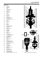
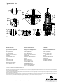
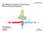
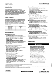
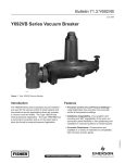
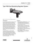
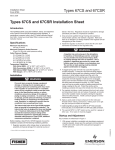
Installation Guide
English – June 2014
Type MR105
Introduction
This installation guide provides instructions for installation,
startup and adjustment. To receive a copy of the
instruction manual, contact your local Sales Office or
view a copy at www.fisherregulators.com. For further
information refer to Type MR105 Instruction Manual,
Form 5874, D103246X012.
P.E.D. Category
This product may be used as a pressure accessory with
pressure equipment in the following Pressure Equipment
Directive 97/23/EC categories. It may also be used
outside of the Pressure Equipment Directive using sound
engineering practice (SEP) per table below.
PRODUCT SIZE
CATEGORIES
NPS 1 / DN 25
SEP
NPS 2 / DN 50
II
NPS 3 / DN 80
II
NPS 4 / DN 100
II
Specifications
Available Constructions
Type MR105 with low-pressure actuator: Directoperated large multi-purpose regulator with
5 to 43 psig / 0.35 to 3.0 bar pressure range.
Type MR105 with high-pressure actuator: Directoperated large multi-purpose regulator with
25 to 300 psig / 1.7 to 20.7 bar pressure range.
Body Sizes and End Connection Styles
DN 25 and 50 / NPS 1 and 2: NPT, CL125 FF,
CL250 RF, CL150 RF, CL300 RF, CL600 RF and
EN PN 16/25/40 RF
DN 80 and 100 / NPS 3 and 4: CL125 FF, CL250 RF,
CL150 RF, CL300 RF, CL600 RF and EN PN 16 RF
Maximum Inlet Pressures(1)
Low-Pressure Actuator: 400 psig / 27.6 bar
High-Pressure Actuator: 400 psig / 27.6 bar
Maximum Outlet Pressures(1)
Low-Pressure Actuator: 70 psig / 4.8 bar
High-Pressure Actuator: 400 psig(2) / 27.6 bar
Maximum Emergency Casing Pressures(1)
Low-Pressure Actuator: 70 psig / 4.8 bar
High-Pressure Actuator: 400 psig(2) / 27.6 bar
Maximum Setpoint(1)
Low-Pressure Actuator: 43 psig / 3.0 bar
High-Pressure Actuator:
Nitrile (NBR) and Ethylene Propylene (EPDM)
Diaphragm: 300 psig / 20.7 bar
Fluorocarbon (FKM) Diaphragm: 150 psig / 10.3 bar
Outlet Pressure Ranges(1)
NPS 1 and 2 / DN 25 and 50:
Low-Pressure Actuator: 5 to 12 psig / 0.35 to 0.83 bar;
10 to 24 psig / 0.69 to 1.6 bar; 14 to 32 psig /
0.96 to 2.2 bar; 18 to 43 psig / 1.2 to 3.0 bar
High-Pressure Actuator: 25 to 60 psig(3) / 1.7 to
4.1 bar; 43 to 100 psig / 3.0 to 6.9 bar; 75 to 175 psig(4) /
5.2 to 12.1 bar; 110 to 300 psig(4) / 7.6 to 20.7 bar
NPS 3 and 4 / DN 80 and 100:
Low-Pressure Actuator: 5 to 8 psig / 0.35 to 0.55 bar;
8 to 20 psig / 0.55 to 1.4 bar; 12 to 30 psig / 0.83 to 2.1 bar;
18 to 39 psig / 1.2 to 2.7 bar
High-Pressure Actuator: 39 to 72 psig / 2.7 to 5.0 bar;
71 to 175 psig(4) / 4.9 to 12.1 bar; 110 to 250 psig(4) /
7.6 to 17.2 bar
Temperature Capabilities(1)
Nitrile (NBR): -20 to 180°F / -29 to 82°C
Fluorocarbon (FKM): 20 to 250°F(5) / -7 to 121°C
Ethylene Propylene (EPDM): -20 to 225°F /
-29 to 107°C(6)
Maximum Differential Pressures(1)
Liquid Application:
Low-Pressure Actuator:
NPS 1 and 2 / DN 25 and 50: 200 psig / 13.8 bar
NPS 3 and 4 / DN 80 and 100: 225 psig / 15.5 bar
High-Pressure Actuator:
NPS 1 / DN 25: 250 psig / 17.2 bar
NPS 2 / DN 50: 200 psig / 13.8 bar
NPS 3 / DN 80: 225 psig / 15.5 bar
NPS 4 DN 100: 250 psig / 17.2 bar
Other Applications:
Low-Pressure Actuator: 400 psig / 27.6 bar
High-Pressure Actuator: 400 psig / 27.6 bar
Maximum Pressures over Set Pressure to Avoid
Internal Parts Damage(1)
Low-Pressure Actuator: 20 psig / 1.4 bar
1. The pressure/temperature limits in this Installation Guide or any applicable limitation should not be exceeded.
2. Maximum Outlet and Emergency Casing Pressures for constructions with Fluorocarbon (FKM) diaphragm are limited to 230 psig / 15.8 bar or the body rating limit, whichever is lower.
3. NPS 2 / DN 50 body size spring range is limited up to 45 psig / 3.1 bar only.
4. Maximum setpoint is limited to 150 psig / 10.3 bar for constructions with Fluorocarbon (FKM) diaphragm.
5. Fluorocarbon (FKM) is limited to 200°F / 93°C hot water.
6. Ethylene Propylene (EPDM) is limited to 20 to 250°F / -7 to 121°C when used with Low Pressure Actuator.
www.fisherregulators.com
D103246XUS2
High-Pressure Actuator: 120 psig / 8.3 bar
Type MR105
Installation
Note
!
Warning
Only qualified personnel should install
or service a regulator. Regulators should
be installed, operated and maintained
in accordance with international and
applicable codes and regulations and
Emerson Process Management Regulator
Technologies, Inc. instructions.
If the regulator vents fluid or a leak
develops in the system, it indicates that
service is required. Failure to take the
regulator out of service immediately may
create a hazardous condition.
Personal injury, equipment damage or
leakage due to escaping fluid or bursting of
pressure-containing parts may result if this
regulator is overpressured or is installed
where service conditions could exceed the
limits given in the Specifications section or
where conditions exceed any ratings of the
adjacent piping or piping connections.
To avoid such injury or damage, provide
pressure-relieving or pressure-limiting
devices (as required by the appropriate
code, regulation or standard) to prevent
service conditions from exceeding limits.
Additionally, physical damage to the
regulator could result in personal injury
and property damage due to escaping fluid.
To avoid such injury and damage, install
the regulator in a safe location.
Clean out all pipelines before installation of the regulator
and check to be sure the regulator has not been damaged
or has collected foreign material during shipping. For
NPT bodies, apply pipe compound to the external pipe
threads. For flanged bodies, use suitable line gaskets and
approved piping and bolting practices.
Vertical installation with the actuator oriented up or down
is recommended. The unit will operate in horizontal
installation with actuator on the side, however, this could
result in premature wear of parts. Make sure that flow will
be in the same direction as that indicated by the body
arrow. Orientation of the two vents should always be down.
Vents may be rotated after regulator installation so that the
vent screens are down.
A control line must be installed to allow outlet pressure to
register on the actuator’s diaphragm. It should be installed
four to eight pipe diameters downstream of the regulator
and in an area of pipe that is free of turbulence.
2
It is important that the regulator be installed
so that the vent hole in the spring case
is unobstructed at all times. For outdoor
installations, the regulator should be
located away from vehicular traffic and
positioned so that water, ice and other
foreign materials cannot enter the spring
case through the vent. Avoid placing the
regulator beneath eaves or downspouts and
be sure it is above the probable snow level.
Overpressure Protection
The recommended pressure limitations are stamped
on the regulator nameplate. Some type of overpressure
protection is needed if the actual inlet pressure exceeds the
maximum operating outlet pressure rating. Overpressure
protection should also be provided if the regulator inlet
pressure is greater than the safe working pressure of the
downstream equipment.
Regulator operation below the maximum pressure
limitations does not preclude the possibility of damage
from external sources or debris in the line. The
regulator should be inspected for damage after any
overpressure condition.
Startup
The regulator is set at the factory for the setpoint specified
on the order or at the midpoint of the spring range. The
allowable spring range is stamped on the nameplate. If a
pressure setting other than specified is desired, be sure to
change the pressure setting by following the Adjustment
section. With proper installation completed and relief
valves properly adjusted, slowly open the upstream and
downstream shutoff valves (if applicable).
Adjustment
To change the outlet pressure, loosen the locknut and
turn the adjusting screw clockwise to increase pressure or
counterclockwise to decrease pressure. Monitor the outlet
pressure with a test gauge during the adjustment. Tighten the
locknut to maintain the desired setting.
Taking Out of Service (Shutdown)
!
Warning
To avoid personal injury resulting from
sudden release of pressure, isolate
the regulator from all pressure before
attempting disassembly.
Type MR105
Parts List
Key
1
2
3
4
5
6
7
8
9
10
11
12
13 14
15 16
17
18
19 20
21
22
23
24 25
26
27
28
29
30 33
34
35
36
37
38
40
43
44
45
46
47
48
49
51
52
53
54
55
56
57
58
60
61
62
63
64
64
65
66
67
68
69
70
71
72
73
75
76
81
82
84
85
87
Description
Valve Body
Body Flange
Stud Bolt
Gasket
Lower Indicator Fitting
O-ring Retainer
Indicator O-ring
Hex Nut
Valve Spring
Indicator Stem
Cage
Port Seal
Seat Ring
Piston Ring
Upper Seal
Valve Plug
Cage O-ring
Travel Indicator Scale
Travel Indicator Protector
Valve Plug O-ring
Lower Indicator Fitting O-ring
Flange Nut
E-Ring
Drive Screw
Flow Arrow
Vent
Plug
Spring Seat
Hex Nut
Pipe Plug
NACE Tag (not shown)
Seal Wire (not shown)
Indicator Fitting
Back O-ring
Indicator Fitting O-ring
Pipe Plug
Actuator Stem
Nameplate
Lube Fitting
Wiper Ring
Bearing
Valve Stem O-ring
Jam Nut
67
Spring
Washer
A
A
Lower Diaphragm Head O-ring
Lower Spring Guide
Lower Diaphragm Head
57
Lower Spring Seat
Diaphragm Plate
Diaphragm
73
Cap Screw or Stud Bolt
Hex Nut
72
Bonnet O-ring
Bonnet
70
Lower Diaphragm Casing
Upper Diaphragm Casing
43
Spring Case Spacer O-ring
Upper Diaphragm Casing O-ring
44
Cap Screw
Spring Case Spacer
30
Cap Screw
Control Spring
Upper Spring Seat
26
Spring Case
Seal Washer (not shown)
38
Jam Nut
Adjusting Screw
1
Restrictor (not shown)
Pipe Bushing
2
Pipe Nipple (not shown)
Drain Valve (not shown)
25 Plate
24
Internal Stiffener
Bleed Valve (not shown)
Upper Casing Welding Assembly (not shown)
69
52
25
68
66
76
65
26
55
63
V
53
56
X
58
65
62
84
Z
13
51
Y
61
12
40
11
17
4
16
9
3
29
67
A
67
57
64
67 43
43
57
73
73
7228 28
72
6
70
70
6
43
4321 21
37 44
4435 30
37
30 8 26
35
2618 38
81
38
182
1 24
2
28
6
21
37
35
8
18
GE38435
67
A
67 4
57 57
69
24
57
73
24
52
73
2464
72
43
7228 2
70
66
23
70 6 6
43
6523
23
10
10
4321 2
44
63 10
5
37
30
56 55
4435
3
26
58
30 8
3
38
62
W
2618
8
1
51
22
22
38
2
61
1
19
19
1 24
24 25
4022 25
2
1719
16
Figure 1. Type MR105 Assembly Drawings
3
3
Type MR105
7
36
46
60
DETAIL W
54
64
47
15
20
14
63
DETAIL X
DETAIL Y
58
47
46
57
45
GE38435
62
49
27
DETAIL Z
56
48
21
NO TRAVEL INDICATOR
53
DETAIL V
Figure 1. Type MR105 Assembly Drawings (continued)
Industrial Regulators
Natural Gas Technologies
TESCOM
Emerson Process Management
Regulator Technologies, Inc.
Emerson Process Management
Regulator Technologies, Inc.
Emerson Process Management
Tescom Corporation
USA - Headquarters
McKinney, Texas 75070 USA
Tel: +1 800 558 5853
Outside U.S. +1 972 548 3574
USA - Headquarters
McKinney, Texas 75070 USA
Tel: +1 800 558 5853
Outside U.S. +1 972 548 3574
USA - Headquarters
Elk River, Minnesota 55330-2445, USA
Tels: +1 763 241 3238
+1 800 447 1250
Asia-Pacific
Shanghai 201206, China
Tel: +86 21 2892 9000
Asia-Pacific
Singapore 128461, Singapore
Tel: +65 6770 8337
Europe
Selmsdorf 23923, Germany
Tel: +49 38823 31 287
Europe
Bologna 40013, Italy
Tel: +39 051 419 0611
Europe
Bologna 40013, Italy
Tel: +39 051 419 0611
Chartres 28008, France
Tel: +33 2 37 33 47 00
Asia-Pacific
Shanghai 201206, China
Tel: +86 21 2892 9499
Middle East and Africa
Dubai, United Arab Emirates
Tel: +011 971 4811 8100
Middle East and Africa
Dubai, United Arab Emirates
Tel: +011 971 4811 8100
For further information visit www.fisherregulators.com
The Emerson logo is a trademark and service mark of Emerson Electric Co. All other marks are the property of their prospective owners. Fisher is a mark owned by Fisher Controls International LLC,
a business of Emerson Process Management.
The contents of this publication are presented for informational purposes only, and while every effort has been made to ensure their accuracy, they are not to be construed as warranties
or guarantees, express or implied, regarding the products or services described herein or their use or applicability. We reserve the right to modify or improve the designs or specifications
of such products at any time without notice.
Emerson Process Management Regulator Technologies, Inc. does not assume responsibility for the selection, use or maintenance of any product. Responsibility for proper selection, use
and maintenance of any Emerson Process Management Regulator Technologies, Inc. product remains solely with the purchaser.
©Emerson Process Management Regulator Technologies, Inc., 2010, 2014; All Rights Reserved