1
Bulletin 71.4:LR128
Table 1. T
ype LR128 Main Valve Body Sizes, End Connection Styles, Structural Design Ratings and Maximum Operating
Relief (Inlet) Pressure(1)
MAIN VALVE
BODY SIZE
In.
MAIN VALVE
BODY
MATERIAL
END CONNECTION STYLE(2)
DN
WCC Steel
1, 2, 3
and 4
STRUCTURAL DESIGN
RATING(3)
25,
50, 80
and 100
CF8M
Stainless steel
maximum operating
relief (inlet)
pressure including
build-up(3)
Maximum Operating
Outlet Pressure
psig
bar
psig
bar
psig
bar
NPT or SWE
(1 and 2 in. only)
1500
103
450
31.0
450
31.0
CL150 RF
290
20.0
290
20.0
290
20.0
51.7
450
31.0
450
31.0
CL300 RF
750
CL600 RF
1500
103
PN 16/25/40 RF
580
40.0
NPT
(1 and 2 in. only)
1440
99.2
450
31.0
450
31.0
275
19.0
275
19.0
450
31.0
450
31.0
CL150 RF
275
19.0
CL300 RF
720
49.6
CL600 RF
1440
99.2
PN 16/25/40 RF
580
40.0
1. The pressure/temperature limits in this Bulletin and any applicable standard or code limitation should not be exceeded.
2. Ratings and end connections for other than ASME standard can usually be provided. Contact your local Sales Office for assistance.
3. Maximum cold working pressure (CWP) per ASME B16.34 or product bulletin limit, whichever is lowest. Temperature may decrease these maximum pressure.
Table 2. Type MR98H Pilot Maximum Cold Working Pressure(1)(2)
BODY SIZE
BODY AND SPRING
CASE MATERIAL
MAXIMUM INLET PRESSURE
MAXIMUM OUTLET PRESSURE
1/2 NPT
Steel
Stainless steel
450 psig / 31.0 bar
450 psig / 31.0 bar
1. The pressure/temperature limits in this Bulletin and any applicable standard or code limitation should not be exceeded.
2. Temperature and/or the body end connection may decrease these maximum pressure.
Table 3. Relief Set Pressure or Backpressure Control Ranges
PILOT
Type MR98H
SET PRESSURE RANGE
SPRING WIRE DIAMETER
SPRING FREE LENGTH
psig
bar
In.
mm
In.
mm
25 to 75
70 to 140
130 to 200
150 to 375(1)
1.7 to 5.2
4.8 to 9.7
9.0 to 13.8
10.3 to 25.9(1)
0.234
0.283
0.331
0.394
5.94
7.19
8.41
10.0
2.595
2.44
2.250
5.063
65.9
62.0
57.2
129
SPRING material
SPRING PART NUMBER
AND COLOR
Powder-coated steel
Powder-coated steel
Powder-coated steel
Powder-coated steel
ERAA01910A0, Green
ERAA01911A0 , Red
ERAA02889A0 , Blue
1N943427142 , Unpainted
1. 150 to 375 psig / 10.3 to 25.9 bar spring range is for the Type MR98HH pilot construction.
Pilot Type Description
Type MR98H – High-pressure relief pilot for 25 to
375 psig / 1.7 to 25.9 bar set pressure. Designed to
handle inlet pressure up to 450 psig / 31.0 bar.
A backpressure regulator is a device that maintains
a desired upstream pressure by varying the flow
in response to changes in upstream pressure. It
functions the same as a relief valve, i.e., it opens on
increasing upstream pressure.
Principle of Operation
Relief Valve
A pressure relief valve is a throttling pressure control
device that limits pressure build-up, it opens to prevent
the rise of internal pressure in excess of a specified
value. Fisher® relief valves cannot be used as ASME
safety relief valves.
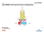
As long as the inlet pressure is below the set pressure,
the Type MR98H pilot control spring keeps the pilot
valve plug closed (Figure 3). Inlet pressure passes
through the Type 112 restrictor and registers as
loading pressure on top of the Type LR128 diaphragm
5