1
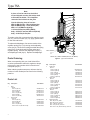
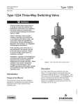
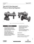
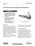
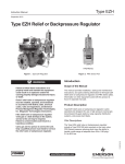
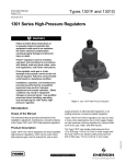
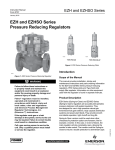
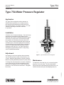
Type 75A
Instruction Manual
Form 511
September 2009
Type 75A Water Pressure Regulator
Application
The Type 75A is designed to reduce domestic or
industrial water pressures to a constant pressure,
thus protecting plumbing fixtures and meters from
high-pressure surges. As shown in Figure 1, it is selfcontained, requiring no external control line
for operation.
Installation
Check the unit for shipment damage. Clean all foreign
material from the pipelines and regulator interior.
Install the Type 75A in a horizontal line with the spring
case above or below the line, and with flow through
the regulator as indicated by the arrow cast on the
body. Coat the external threads with pipe compound
and draw up the connections tightly but not severely.
If a snap-acting valve (solenoid valve) is used in the
system, the snap-acting valve should be installed
upstream of the Type 75A. The Type 75A may be
damaged by high shutoff pressure if a snap-acting
valve is installed downstream.
W0057-1
Adjustment
One spring for each size regulator allows operation
over an outlet pressure range of 20 to 80 psi (1,4 to
5,5 bar). Maximum inlet pressure is 200 psi (13,8 bar).
Minimum operating differential pressure is 5 psi (0,34 bar).
Maintenance
To replace the valve disk (key 13), unscrew the guide
plug (key 3) from the body. The valve disk holder
(key 5) may now be unscrewed from the yoke (key 4). Be
careful not to twist and rupture the diaphragm (key 12).
D100254X012
To change the reduced pressure, loosen the adjusting
screw locknut (key 9) and turn the adjusting screw
(key 8) into the spring case to increase the reduced
pressure, or out of the case to decrease it. Re-tighten
the locknut.
Figure 1. Type 75A Water Pressure Regulator
www.emersonprocess.com/regulators
Type 75A
Note
A piece of hex bar stock can be drilled
out and slipped over the disk holder shaft
to fit inside the holder. This simplifies
removal of the holder from the yoke.
8
9
10
11
Use the following sizes of hex bar:
NPS 1/2 (DN 15) body – 7/8-inch (22 mm) hex;
NPS 3/4 (DN 20) body – 1-inch (25 mm) hex;
NPS 1 or 1-1/2 (DN 25 or 40) body –
1-1/4-inch (32 mm) hex; NPS 2 (DN 50)
body – 2-inch (51 mm) hex; NPS 2-1/2 (DN 65)
body – 2-1/2-inch (63 mm) hex.
2
7
6
12
14
To replace valve disk, unscrew the disk retaining screw
(key 16), remove old disk (key 13), apply gasket sealer
to new disk and install.
To replace the diaphragm, first remove tension of the
regulator spring (key 11) by turning out the adjusting
screw (key 8). Remove the bolting that holds the spring
case (key 2) to the body and lift off the casing and
regulator spring. Unscrew the diaphragm nut (key 7)
and diaphragm head (key 6). Replace the diaphragm.
When ordering replacement parts, reference the key
number of each needed part as found in the following
parts list.
Parts List
2
17
13
16
5
apply gaskalac
3
20A5581-B
A0209
Figure 2. Type 75A Assemblies
When corresponding with your local Sales Office
or sales representative about this regulator, always
reference the type number which is found on the
nameplate (key 21).
1
Body
Bronze
NPS 1/2 (DN 15)
NPS 3/4 (DN 20)
NPS 1 (DN 25)
NPS 1-1/2 (DN 40)
NPS 2 (DN 50)
NPS 2-1/2 (DN 65)
2
Spring Case
Cast Iron
NPS 1/2 (DN 15)
NPS 3/4 (DN 20)
NPS 1 (DN 25)
NPS 1-1/2 (DN 40)
NPS 2 and 2-1/2 (DN 50 and 65)
1
NPS 1/2, 3/4, 1, and 1-1/2 Body (DN 15, 20, 25, and 40)
Parts Ordering
Key Description
4
Part Number
2A940812012
2D226312012
2V361512012
3D174012012
3D626712012
3E231012012
1D878619042
00085719042
2A480119042
3V361319042
00132019042
Key Description
3
Guide Plug
Bronze
NPS 1/2 (DN 15)
NPS 3/4 (DN 20)
NPS 1 (DN 25)
NPS 1-1/2 (DN 40)
NPS 2 (DN 50)
NPS 2-1/2 (DN 65)
4
Valve Yoke
Bronze
NPS 1/2 (DN 15)
NPS 3/4 (DN 20)
NPS 1 (DN 25)
NPS 1-1/2 (DN 40)
NPS 2 (DN 50)
NPS 2-1/2 (DN 65)
5
Valve Disk Holder
Bronze
NPS 1/2 (DN 15)
NPS 3/4 (DN 20)
NPS 1 (DN 25)
NPS 1-1/2 (DN 40)
NPS 2 (DN 50)
NPS 2-1/2 (DN 65)
6
Diaphragm Head
NPS 1/2 (DN 15), Steel
NPS 3/4 (DN 20), Cast Iron
NPS 1 (DN 25), Cast Iron
NPS 1-1/2 (DN 40), Cast Iron
NPS 2 and 2-1/2 (DN 50 and 65), Cast Iron
Part Number
0W099412012
1A971912012
1A950812012
1A974612012
1A975212012
0D023212012
1A942712012
1A945512012
1A951412012
2V361412012
2V361612012
2V361712012
1B590112012
1B590212012
1B867312012
1B867712012
1B867912012
1B869812012
1A941524092
1A945619042
1A950919052
1V361219042
1A975819042
Type 75A
8
9
8
9
10
10
11
11
2
2
7
7
14
15
6
1
12
4
20
14
15
12
4
19
19
16
16
5
5
13
apply
gaskalac
3
Figure 2. Type 75A Assemblies (continued)
7
Diaphragm Nut
Steel
NPS 1/2 (DN 15)
NPS 3/4 (DN 20)
NPS 1 (DN 25)
NPS 1-1/2 (DN 40)
NPS 2 and 2-1/2 (DN 50 and 65)
8
Set Screw
Zinc-plated steel
NPS 1/2 (DN 15)
NPS 3/4 (DN 20)
NPS 1 and 1-1/2 (DN 25 and 40)
NPS 2 and 2-1/2 (DN 50 and 65)
9
Hex Nut
Brass
NPS 1/2 and 3/4 (DN 15 and 20)
NPS 1 and 1-1/2 (DN 25 and 40)
NPS 2 and 2-1/2 (DN 50 and 65)
10
Spring Seat
Steel
NPS 1/2 and 3/4 (DN 15 and 20)
NPS 1 (DN 25)
NPS 1-1/2 to 2-1/2 (DN 40 to 65)
11
Spring
Spring wire
NPS 1/2 (DN 15)
NPS 3/4 (DN 20)
NPS 1 (DN 25)
NPS 1-1/2 (DN 40)
NPS 2 and 2-1/2 (DN 50 and 65)
Part Number
17
3
30A5580-A
A0212
NPS 2 (DN 50) Body
Key Description
1
13
apply
gaskalac
17
30A5582-A
A0211
6
NPS 2-1/2 (DN 65) Body
Figure 2. Type 75A Assemblies (continued)
Key Description
1A941424092
1E478524092
1V361124092
1A974824092
1A982424092
1C216032992
1A514428992
1F575328992
1V360928982
1A518014012
1A352414012
1A599314012
1E478424092
1V361024092
1A975424092
1V360527022
1V360627142
1V360727142
1V360827142
1C398227042
Diaphragm
Neoprene (CR)
NPS 1/2 (DN 15)
NPS 3/4 (DN 20)
NPS 1 (DN 25)
NPS 1-1/2 (DN 40)
NPS 2 and 2-1/2 (DN 50 and 65)
13* Valve Disk
Nitrile (NBR)
NPS 1/2 (DN 15)
NPS 3/4 (DN 20)
NPS 1 (DN 25)
NPS 1-1/2 and 2 (DN 40 and 50)
NPS 2-1/2 (DN 65)
14
Cap Screw
Zinc-plated steel
NPS 1/2 (DN 15) (6 required)
NPS 3/4 (DN 20) (6 required)
NPS 1 (DN 25) (8 required)
NPS 1-1/2 (DN 40) (8 required)
NPS 2 (DN 50) (10 required)
NPS 2-1/2 (DN 65) (4 required)
15
Hex Nut
Zinc-plated steel
NPS 1/2 (DN 15) (6 required)
NPS 3/4 (DN 20) (6 required)
NPS 1 and 1-1/2 (DN 25 and 40) (8 required)
NPS 2 (DN 50) (10 required)
NPS 2-1/2 (DN 65) (6 required)
Part Number
12*
1A941002112
1A946102112
1A951102112
1A974302112
1A975502112
1C158203022
1C158603022
1C158703022
1C158903022
1C159803022
1B720924052
1A352624052
1A368324052
1A353024052
1A569824052
1A582324052
1A3915X0022
1A352724122
1A346524122
1A353724122
1A341224122
*Recommended spare part.
3
Type 75A
Key Description
16
Machine Screw
Brass
NPS 1/2 (DN 15)
NPS 3/4 and 1 (DN 20 and 25)
NPS 1-1/2 and 2 (DN 40 and 50)
NPS 2-1/2 (DN 65)
17
Disk Retainer Washer
Brass
NPS 3/4 (DN 20)
NPS 1 (DN 25)
NPS 1-1/2 and 2 (DN 40 and 50)
NPS 2-1/2 (DN 65)
Part Number
1A8991X0012
0V070414012
1D567314012
J17796X0012
0B078214012
00147614012
1A975014012
0D023314012
Key Description
Part Number
19* Orifice
Bronze
NPS 2 (DN 50)
NPS 2-1/2 (DN 65)
20
Cap Screw
Zinc-plated steel
NPS 2-1/2 (DN 65) (6 required)
21
Nameplate (not shown)
22
Drive Screw (not shown)
1A980512012
1A981012012
1A344424052
11B6112X012
1A676728992
*Recommended spare part.
Industrial Regulators
Natural Gas Technologies
TESCOM
Emerson Process Management
Regulator Technologies, Inc.
Emerson Process Management
Regulator Technologies, Inc.
Emerson Process Management
Tescom Corporation
USA - Headquarters
McKinney, Texas 75069-1872 USA
Tel: 1-800-558-5853
Outside U.S. 1-972-548-3574
USA - Headquarters
McKinney, Texas 75069-1872 USA
Tel: 1-800-558-5853
Outside U.S. 1-972-548-3574
USA - Headquarters
Elk River, Minnesota 55330-2445 USA
Tel: 1-763-241-3238
Asia-Pacific
Shanghai, China 201206
Tel: +86 21 2892 9000
Asia-Pacific
Singapore, Singapore 128461
Tel: +65 6777 8211
Europe
Bologna, Italy 40013
Tel: +39 051 4190611
Europe
Bologna, Italy 40013
Tel: +39 051 4190611
Gallardon, France 28320
Tel: +33 (0)2 37 33 47 00
Middle East and Africa
Dubai, United Arab Emirates
Tel: +971 4811 8100
Europe
Selmsdorf, Germany 23923
Tel: +49 (0) 38823 31 0
For further information visit www.emersonprocess.com/regulators
The Emerson logo is a trademark and service mark of Emerson Electric Co. All other marks are the property of their prospective owners. Fisher is a mark owned by Fisher Controls, Inc., a
business of Emerson Process Management.
The contents of this publication are presented for informational purposes only, and while every effort has been made to ensure their accuracy, they are not to be construed as warranties or
guarantees, express or implied, regarding the products or services described herein or their use or applicability. We reserve the right to modify or improve the designs or specifications of such
products at any time without notice.
Emerson Process Management does not assume responsibility for the selection, use or maintenance of any product. Responsibility for proper selection, use and maintenance of any Emerson
Process Management product remains solely with the purchaser.
©Emerson Process Management Regulator Technologies, Inc., 1945, 2009; All Rights Reserved