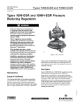
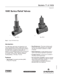
1
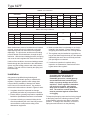
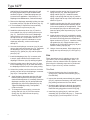
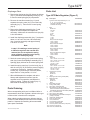
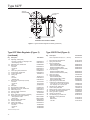
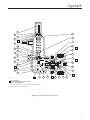
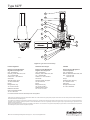
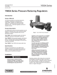
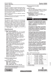
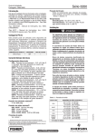
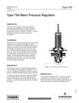
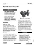
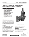
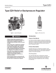
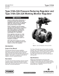
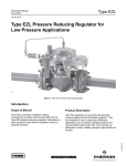
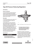
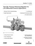
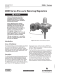
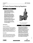
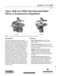
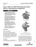
Type 627F
Instruction Manual
Form 5282
April 2012
Type 627F Pilot-Operated
Pressure Reducing Regulator
W5607
W5641
Figure 1. Type 627F Pilot-Operated Pressure Reducing Regulators
!
WARNING
Failure to follow these instructions or
to properly install and maintain this
equipment could result in an explosion
and/or fire causing property damage and
personal injury or death.
Call a gas service person to service
the unit. Only a qualified person must
install or service the regulator.
Introduction
Scope of the Manual
This manual provides instructions for installation,
adjustment, maintenance, and parts ordering
information for the Type 627F regulator.
D101545X012
Fisher® regulators must be installed,
operated, and maintained in
accordance with federal, state, and
local codes, rules and regulations,
and Emerson Process Management
Regulator Technologies, Inc. (Regulator
Technologies) instructions.
If the regulator vents gas or a leak
develops in the system, service to the
unit may be required. Failure to
correct trouble could result in a
hazardous condition.
www.fisherregulators.com
Type 627F
Specifications
The Specifications section gives some general specifications for the Type 627F regulator. The nameplates
give detailed information for a particular regulator as it comes from the factory.
Body Sizes and End Connection Styles
Ductile iron: 3/4, 1, or 2 NPT
Steel: 3/4, 1, or 2 NPT;
NPS 1 or 2 / DN 25 or 50, CL150 RF,
CL300 RF, CL600 RF, PN 16/25/40 RF Flanged
Flow Coefficients
See Table 4
Minimum Pressure Differential
20 psid / 1.4 bar d
Pressure Registration
External
Maximum Inlet and Differential Pressures(1)
See Table 2
Pilot Supply Connection
1/4 NPT
Maximum Emergency Outlet Pressure(1)
250 psig / 17.2 bar for all Type 627F actuators and
Type 6351F pilot components
Pilot Sense Connection
1/4 NPT
Outlet Pressure Ranges
5 to 100 psig / 0.34 to 6.9 bar
See Table 1
IEC Sizing Coefficients
See Table 5
Body Tap Connection
1/4 NPT (ductile iron body only)
Approximate Weights
NPT body with Ductile iron or steel casings: 10 pounds / 4 kg
NPT body with aluminum casings: 6.3 pounds / 3 kg
Flanged body with steel casings:
18 pounds / 8 kg
Flanged body with Ductile iron casings:
14 pounds / 6 kg
Orifice Sizes
3/8 x 1/8, 3/8 x 1/4, 3/8, or 1/2 inch /
9.5 x 3.2; 9.5 x 6.4; 9.5; or 13 mm
Temperature Capabilities(1)
-20 to 180°F / -29 to 82°C
1. The pressure/temperature limits in this Instruction Manual or any applicable standard limitation should not be exceeded.
Table 1. Outlet Pressure Ranges
PILOT TYPE
6351F
PILOT CONTROL SPRING INFORMATION
OUTLET PRESSURE RANGE
psig
bar
5 to 35
35 to 100
0.34 to 2.4
2.4 to 6.9
Part Number
Color Code
1B788327022
1K748527022
Unpainted
Red
Wire Diameter
Free Length
inches
mm
inches
mm
0.142
0.192
3.61
4.88
2.13
2.19
54.1
55.6
Table 2. Maximum Allowable Inlet Pressures and Pressure Differential
ORIFICE SIZE
2
MAXIMUM INLET PRESSURE
MAXIMUM PRESSURE DIFFERENTIAL
inch
mm
psig
bar
psig
bar
3/8 x 1/8
3/8 x 1/4
3/8
1/2
9.5 x 3.2
9.5 x 6.3
9.5
13
250
250
250
125
17.2
17.2
17.2
8.6
250
250
250
125
17.2
17.2
17.2
8.6
Type 627F
FIELD INSTALLED
DOWNSTREAM
CONTROL LINE
SPRING SEAT BOLT
(THIS IS NOT AN
ADJUSTING SCREW)
RESTRICTION
(BLEED)
FILTER (FACTORY
INSTALLATION
OPTIONAL)
TENSION SPRING
MAIN REGULATOR
DIAPHRAGM
PILOT DIAPHRAGM
LEVER
PILOT ADJUSTING
SCREW
TYPE 6351F PILOT
VALVE DISK
TYPE 627F REGULATOR
A6558
INLET
INLETPRESSURE
PRESSURE
OUTLET
OUTLETPRESSURE
PRESSURE
ATMOSPHERIC
PRESSURE
ATMOSPHERIC
PRESSURE
LOADING
PRESSURE
LOADING
PRESSURE
PILOT SUPPLY TUBING
(FACTORY INSTALLATION OPTIONAL)
INTERMEDIATE PRESSURE
PILOT SUPPLY PRESSURE
VACUUM PRESSURE
TANK PRESSURE
Figure 2. Type 627F Pilot-Operated Pressure Reducing Regulator Operational Schematic
VAPOR PRESSURE
Table 3. Additional Specifications
ALLOWABLE INLET PRESSURE RANGE FOR MAINTAINING OUTLET PRESSURE
WITHIN ±1% OF THE ABSOLUTE OUTLET PRESSURE SETTING(1)
ORIFICE SIZE
5 psig / 0.34 bar
30 psig / 2.1 bar
40 psig / 2.8 bar
60 psig / 4.1 bar
inch
mm
psig
bar
psig
bar
psig
bar
psig
bar
100 psig / 6.9 bar
psig
bar
3/8 x 1/8
3/8 x 1/4
3/8
1/2
9.5 x 3.2
9.5 x 6.4
9.5
13
30 to 250
30 to 250
30 to 250
25 to 125
2.1 to 17.2
2.1 to 17.2
2.1 to 17.2
1.7 to 8.6
55 to 250
55 to 250
55 to 250
50 to 125
3.8 to 17.2
3.8 to 17.2
3.8 to 17.2
3.4 to 8.6
65 to 250
65 to 250
65 to 250
60 to 125
4.5 to 17.2
4.5 to 17.2
4.5 to 17.2
4.1 to 8.6
85 to 250
85 to 250
85 to 250
80 to 125
5.9 to 17.2
5.9 to 17.2
5.9 to 17.2
5.9 to 8.6
125 to 250
125 to 250
125 to 250
120 to 125
8.6 to 17.2
8.6 to 17.2
8.6 to 17.2
8.3 to 8.6
1. For best performance, outlet pressure setting should be made using an inlet pressure that is midway between the highest and lowest expected inlet pressure.
Description
The Type 627F pilot-operated (Type 6351F pilot)
pressure reducing regulator (Figure 1) provides
economical, accurate pressure control in a wide variety
of applications using pressure factor measurement
(fixed factor billing). The regulator can be used with
natural gas, air, or a variety of other gases.
Principle of Operation
The superior performance of a Type 627F regulator is
due to the amplifying effect of the pilot and the two-path
control system (Figure 2). Changes in outlet pressure
act quickly on the main regulator diaphragm which
repositions the valve disk to provide fast response to
system changes. Simultaneously, the pilot amplifies
system pressure changes to position the main
regulator valve disk for precise pressure control.
Inlet pressure is used for the pilot supply pressure.
If downstream flow increases, lowering the outlet
pressure below the regulator setpoint, pressure on
the pilot diaphragm and the lever side of the main
regulator diaphragm decreases. The pilot opens to
supply the required loading pressure increase. The
increased loading pressure from the pilot overcomes
the main regulator spring force, and the main
regulator valve disk moves farther open to supply the
required flow.
3
Type 627F
Table 4. Flow Coefficients
3/4 NPT BODY
ORIFICE SIZE
Wide-Open Wide-Open
inches
mm
Cg
Cv
3/8 x 1/8
9.5 x 3.2
12.5
0.43
3/8 x 1/4
9.5 x 6.4
50
1.63
3/8
9.5
108
1/2
13
190
NPS 1 / DN 25 BODY
C1
Wide-Open Wide-Open
Cg
Cv
29.1
12.5
0.43
30.6
50
1.71
2.99
36.1
108
4.87
39.0
190
NPS 2 / DN 50 BODY
C1
Wide-Open Wide-Open
C1
Cg
Cv
29.4
12.5
0.43
29.2
29.3
52
1.66
31.3
3.42
31.6
11.5
3.39
33.9
5.29
35.9
200
5.01
39.9
Table 5. IEC Sizing Coefficients
ORIFICE SIZE
XT
inches
mm
3/4 NPT Body
NPS 1 / DN 25 Body
NPS 2 / DN 50 Body
1/8
3.2
0.54
0.55
0.54
1/4
6.4
0.59
0.54
0.62
3/8
9.5
0.82
0.63
0.73
1/2
13
0.96
0.82
1.01
When downstream pressure increases due to lowered
demand, greater pressure is registered on the pilot
diaphragm and the lever side of the main regulator
diaphragm. The pilot closes, and the excess loading
pressure bleeds off to downstream, through the pilot
restriction. With the lower loading pressure, the spring
can move the main regulator disk closer to the orifice.
Under no flow conditions, the excess loading pressure
bleeds through the pilot restriction to the downstream
system until the loading pressure and outlet pressure
equalize. The main valve is closed by the spring and
the bleed stops.
Installation
Only personnel qualified through training and
experience should install, operate, or maintain this
regulator. Regulator operation within ratings does
not preclude the possibility of damage from debris
in the lines or from external sources. Key numbers
referenced in this section are shown in Figures 3 and 4.
1. A regulator should be inspected for damage
periodically and after any overpressure condition.
2. Ensure that the operating temperature capabilities
listed in the Specifications section are not exceeded.
3. A pressure-relieving or pressure-limiting device
must be provided by the user if the inlet pressure
can exceed the outlet pressure rating of the
downstream equipment.
4
FD
FL
0.79
0.50
0.87
0.89
0.86
4. Make sure that there is no damage to, or foreign
material in the regulator. Ensure that all tubing
and piping have been blown free of foreign debris.
5. The regulator may be installed in any position as
long as the flow through the body is in the direction
indicated by the arrow cast on the body and both
pilot openings are connected.
6. If continuous operation is required during
inspection or maintenance, install a three-valve
bypass around the regulator.
!
WARNING
A regulator may vent some gas to
the atmosphere. In hazardous or
flammable gas service, vented gas may
accumulate and cause personal injury,
death, or property damage due to fire or
explosion. Vent a regulator in hazardous
gas service to a remote, safe location
away from air intakes or any hazardous
area. The vent line or stack opening
must be protected against condensation
or clogging.
To keep the pilot spring case vent from being plugged
or the spring case from collecting moisture or other
foreign material, point the vent down or otherwise
protect it. To change vent orientation, remove the
spring case and remount it on the pilot body.
Type 627F
To remotely vent the pilot, remove the vent and install
obstruction-free tubing or piping into the 1/4 NPT
vent tapping. Provide protection on a remote vent by
installing a screened vent cap into the remote end of
the vent pipe.
If the regulator requires repositioning, refer to the
Body Area Maintenance procedures and/or the
Diaphragm Case Area Maintenance procedures in
the Maintenance section to reposition the regulator
for the application.
The Type 627F regulator requires a downstream control
line. Install the control line before putting the regulator
into operation. Ensure that the downstream control
line piping is at least 3/8 inch / 9.5 mm or larger outside
diameter tubing and connected to a straight section of
outlet piping several pipe diameters downstream of the
regulator. Connect the other end of the control line to
the pilot side connection (marked “sense”).
The Type 627F regulator also requires inlet pressure to
be piped to the pilot supply connection (see Figure 2).
If the optional factory pilot supply piping was not
selected, run a 3/8 inch / 9.5 mm outer diameter or
larger supply line from the upstream pipeline or from
the 1/4 NPT body tap (ductile iron body only) to the
pilot inlet connection marked “in”.
Do not make the upstream pipeline connection in a
turbulent area, such as near a nipple, swage, or elbow.
To properly isolate the regulator, install a hand valve in
the pilot supply line, and provide vent valves to relieve
pressure from the regulator.
Overpressure Protection
!
WARNING
Personal injury, property damage,
equipment damage, or leakage
due to escaping gas or bursting of
pressure-containing parts may result
if this regulator is overpressured or
is installed where service conditions
could exceed the limits given in
Specifications section or where
conditions exceed any ratings of the
adjacent piping or piping connections.
To avoid such injury or damage, provide
pressure-relieving or pressure-limiting
devices (as required by the appropriate
code, regulation, or standard) to
prevent service conditions from
exceeding limits.
Additionally, physical damage to the
regulator could cause personal injury or
property damage due to escaping gas.
To avoid such injury or damage, install
the regulator in a safe location.
Startup and Adjustment
Startup
!
WARNING
To avoid personal injury or property
damage due to explosion or damage to
regulator or downstream components
during startup, release downstream
pressure to prevent an overpressure
condition on the diaphragm of
the regulator.
In order to avoid an overpressure
condition and possible equipment
damage, pressure gauges should
always be used to monitor pressures
during startup.
1. Slowly open the upstream shutoff valves to the
pilot and the regulator inlet.
2. Slowly open the downstream shutoff valves to the
pilot sense connection and the regulator outlet.
3. Check all connections for leaks.
4. Make final pilot control spring adjustments
according to the Adjustment procedures. Standard
factory setpoint is approximately mid-range of the
pilot spring range.
Adjustment
The range of allowable pressure settings is marked
on the pilot. If a pressure setting beyond this range
is necessary, substitute the appropriate pilot control
spring. Change the pilot stamping to indicate the new
pressure range.
The only adjustment necessary on a Type 627F
regulator is the pressure setting of the pilot control
spring. Turning the pilot adjusting screw clockwise
into the spring case increases the spring compression
and pressure setting. Turning the pilot adjusting screw
counterclockwise decreases the spring compression
and pressure setting.
5
Type 627F
Table 6. Recommended Torque Values
KEY NUMBER(1)
DESCRIPTION
FOOT-POUNDS
NEWTON METERS
Orifice
25
34
Cap Screw (with aluminum diaphragm casing)
16
22
Type 627F Actuator
2
3
Cap Screw (with ductile iron or steel diaphragm casing)
25
34
18
Cap Screw Lever
7
9,5
36
Closing Cap
40
54
Spring Case Cap Screw (with aluminum or ductile iron diaphragm casing)
7
9,5
37
Spring Case Cap Screw (with steel diaphragm casing)
35
47
53
Spring Retainer
3
4.1
54
Diaphragm Connector
7
9.5
3
Body Plug
6
8.1
12
Machine Screw
3
4.1
Type 6351F Pilot
1. Refer to Figures 3 and 4 for key number locations.
Note
Always use a pressure gauge to monitor
pressure when making adjustments.
Shutdown
!
WARNING
To avoid personal injury, property
damage due to explosion, or damage
to regulator or downstream
components during shutdown, release
downstream pressure to prevent
an overpressure condition on the
diaphragm of the regulator.
1. Close the upstream shutoff valves to the pilot and
regulator inlets.
2. Close the downstream shutoff valves to the pilot
sense connection and the regulator outlet.
3. Slowly open the vent valve on the downstream
side of the regulator to vent all pressures.
Maintenance
Due to normal wear, damage from external sources,
or debris in the air or gas line, regulator parts such
as the disk assembly, orifice, and diaphragm must
be inspected periodically and replaced as necessary
6
to ensure correct performance. The frequency of
inspection and replacement depends upon the severity
of conditions and the requirements of applicable
laws. Normal wear of the orifice and disk assembly
is accelerated with high-pressure drops and with
impurities in the flow stream.
Due to the care Regulator Technologies takes
in meeting all manufacturing requirements (heat
treating, dimensional tolerances, etc.), use only
replacement parts manufactured or furnished by
Fisher®. Instructions are given below for replacing the
disk assembly, orifice, diaphragm, and O-rings. These
procedures may also be used for disassembly required
for inspection and replacement of other parts.
Body Area Maintenance Procedures
!
WARNING
Isolate the regulator from all pressure
to avoid personal injury and equipment
damage due to explosion or sudden
release of process pressure. Cautiously
release all pressure from the regulator
before attempting disassembly.
The disk assembly and orifice can be inspected,
removed, and replaced without removing the
regulator body from the line connections. If the
disk assembly and orifice are not damaged, refer to
the Diaphragm and Spring Case Area Maintenance
procedures in this section.
Type 627F
These procedures are for gaining access to the disk
assembly, orifice, diaphragm casing, O-ring, and stem
assembly. All pressure must be released from the
regulator before the following steps can be performed.
Refer to Figure 3 for key number locations.
Replacing the Disk Assembly or Orifice
If it is necessary to perform maintenance on the disk
assembly (key 9) or orifice (key 2), continue with the
following steps:
1. Remove the closing cap (key 36) and loosen the
lock nut (key 34) relieving tension spring pressure.
Hold the spring seat bolt (key 61) to prevent
turning of the bolt from the tension spring (key 32).
Remove the cap screws (key 3), and separate the
diaphragm casing (key 5) from the body (key 1).
Note
If the body cap screws (key 3) are evenly
removed and replaced very carefully,
then the tension spring force will not
need to be released.
2. Inspect and, if necessary, remove the orifice
(key 2). If removed, coat the threads of the
replacement orifice with lubricant and torque to
25 foot-pounds / 34 N•m.
3. Inspect the disk assembly and, if necessary,
remove the hairpin clip (key 13) that holds the
disk assembly (key 9) in place. If replacing the
disk assembly is the only maintenance required,
refer to the Startup procedure.
Replacing the Stem Assembly
If it is necessary to perform maintenance on the stem
assembly, continue with the following steps.
1. Remove the boost body (key 6), O-ring (key 7),
and stem guide (key 8) from the diaphragm casing
(key 5). Unhook the stem (key 10) from the lever
(key 15) and remove from the diaphragm casing
(key 5).
2. Remove and inspect the diaphragm casing O-ring
(key 4) and stem O-ring (key 11), replace
if necessary.
3. Install the replacement diaphragm casing O-ring
(key 4) onto the boost body (key 6). Apply lubricant
to the stem O-ring and install on the stem (key 10).
4. Apply lubricant to the stem (key 10) and insert the
stem into the diaphragm casing (key 5) and hook it
on the lever (key 15).
5. Apply lubricant to the O-ring (key 7) and insert
parts removed in steps 1 and 2 into the diaphragm
casing (key 5).
6. Install the disk assembly (key 9), line up the hole
in the disk assembly and stem (keys 9 and 10) and
insert the hairpin clip (key 13).
7. Position the diaphragm casing plus attached parts
in relation to the body (key 1) so that they are
correct for the application.
8. Secure the diaphragm casing to the body with
the cap screws (key 3). For an aluminum
diaphragm casing (key 5), torque the cap screws
(key 3) to 16 foot-pounds / 22 N•m. For ductile
iron or steel diaphragm casings, torque the
cap screws (key 3) to 25 foot-pounds / 34 N•m.
Torque the two body cap screws (key 3) very
evenly to square up the orifice (key 2) and disk
assembly (key 9) seating relationship.
9. It may be necessary to reposition the diaphragm
spring case to prevent rain, ice, and foreign debris
from entering the pilot spring case through the vent.
Diaphragm and Spring Case Area
Maintenance Procedures
These procedures are for gaining access to the tension
spring, diaphragm assembly, and lever assembly. All
spring pressure must be released from the diaphragm
casing before these steps can be performed. Refer to
Figure 3 for key number locations.
1. To release the tension spring force, remove
the closing cap (key 36), the lock nut (key 34),
and washer (key 62). Hold the spring seat bolt
(key 61) to prevent turning of the bolt from the
tension spring (key 32).
2. Remove the spring case cap screws (key 37), the
nameplates, and lift off the spring case (key 29). If
changing the tension spring (key 32) or repositioning
the spring case (key 29) is the only maintenance
required, remove the spring seat bolt (key 61) from
the tension spring (key 32) and unscrew the spring
retainer (key 53). Install the replacement tension
spring. Install left hand threaded end of spring
7
Type 627F
seat bolt (key 61) into tension spring (key 32) until
the spring is flush with the top of the bolt threads
as shown in Figure 3. Rotate the spring case so it
is correct for the application. Skip to step 14. For
Diaphragm Area Maintenance, continue with step 3.
3. Remove the diaphragm assembly by tilting it so that
the pusher post (key 19) slips off the lever (key 15).
4. If it is necessary to replace the lever assembly,
remove the lever cap screws (key 18).
5. Install the replacement lever (key 15) into the
lever retainer (key 16) by inserting the lever pin
(key 17). Secure the lever into the diaphragm
casing with the cap screws (key 18) and torque
the cap screws to 7 foot-pounds / 9.5 N•m. If
it is necessary to perform maintenance on the
diaphragm assembly, continue with steps 6
through 15.
6. Unscrew the diaphragm connector (key 54) and
remove the lower spring seat (key 31). Separate
the diaphragm (key 23) from the diaphragm
head (key 24), gasket (key 55) and the pusher
post (key 19).
7. Install the diaphragm (key 23), in reverse order
in step 6, apply lubricant to the threads of the
diaphragm connector (key 54) and finger tighten.
8. Hook the pusher post on the lever (key 15), then
turn the diaphragm (key 23) to match the holes in
the diaphragm with the holes in the spring casing.
9. Unhook the pusher post from the lever, hold the
pusher post and torque the diaphragm connector
(key 54) to 7 foot-pounds / 9.5 N•m.
10. Apply lubricant to the pusher post (key 19), then
hook the pusher post on the lever (key 15) and
check the hole alignment. If necessary, loosen the
diaphragm connector (key 54) and reposition the
diaphragm (key 23) on the pusher post (key 19).
Tighten the diaphragm using 7 foot-pounds /
9.5 N•m of torque.
11. To change the tension spring, remove the
spring seat bolt (key 61) from the tension
spring (key 32) and unscrew the spring
retainer (key 53).
8
12. Install the tension spring (key 32) on the lower
spring seat (key 31), insert and tighten the
spring retainer (key 53). Install the tension
spring on the spring seat bolt (key 61) until the
spring is flush with the top of the bolt threads as
shown in Figure 3.
13. Install the spring case (key 29) over the spring
seat bolt and so that the pilot assembly will be
in the correct position for the application. Place
the nameplate (key 39) over the screw holes,
insert the spring case cap screws (key 37), and
finger tighten.
14. Install the locknut (key 34), and hold the spring
seat bolt (key 61) to prevent turning, by running
the locknut all the way down the threads and
tighten as shown in Figure 3. Install the closing
cap gasket (key 63). Apply lubricant to the
threads on top of the spring case (key 29) and
install the closing cap (key 36).
15. Using a crisscross pattern, finish tightening the
spring case cap screws (key 37, see Figure 3).
Pilot
These procedures are for gaining access to the
Type 6351F pilot trim and diaphragm parts. All
pressure must be released from the regulator and
pilot before the following steps can be performed.
Refer to Figure 4 for key number locations.
Trim Parts
1. Remove the body plug (key 3) and the valve
spring (key 6), and inner valve assembly (key 4)
from the body.
2. Inspect the removed parts and body plug gasket
(key 23), replace as necessary, and make sure the
plug seating surfaces are free from debris.
3. Sparingly apply lubricant to the body plug gasket
(key 23) and the threads of the body plug (key 3).
Install the body plug gasket over the body plug.
4. Install the plug spring (key 6), and inner valve
assembly (key 4) into the body (key 1). Torque the
body plug (key 3) to 6 foot-pounds / 8.1 N•m.
Type 627F
Parts List
Diaphragm Parts
1. Remove the closing cap (key 28), loosen the locknut
(key 11), and back out the adjusting screw (key 10)
to remove control spring (key 9) compression.
Type 627F Main Regulator (Figure 3)
2. Remove the machine screws (key 12) and
separate the spring case (key 2) from the body
assembly (key 1). Remove the control spring
(key 9).
Type 627F Parts Kit (includes keys 4, 7, 9,
11, 12, 13, 23, 55, and 63)
Aluminum or Ductile iron casing Stainless steel casing 3. Remove the diaphragm assembly (key 7) and
inspect the removed parts and replace as
necessary. Make sure the restriction hole (key 44)
is free from debris.
4. Install the diaphragm assembly (key 7) and push
down on it to see if the inner valve assembly
(key 4) strokes smoothly and approximately
1/16-inch / 2.0 mm.
Note
In step 5, if installing a control spring of
a different range from the one that was
removed, be sure to replace the spring
range originally appearing on the spring
case with the new spring range.
5. Stack the control spring (key 9) and control spring
seat (key 8) onto the diaphragm assembly (key 7).
Sparingly apply lubricant to the control spring seat.
6. Install the spring case (key 2) on the body (key 1)
with the vent (key 35) oriented to prevent clogging
or entrance of moisture. Install the machine
screws (key 12) and using a crisscross pattern,
torque them to 3 foot-pounds / 4.1 N•m.
7. When all Maintenance is complete, refer to the
Startup and Adjustment section to put the
regulator back into operation, and adjust the
pressure setting. Tighten the locknut (key 11),
and install the closing cap (key 28).
Parts Ordering
When corresponding with your local Sales Office or
representative about this regulator, reference the type
number which is found on the nameplate.
When ordering replacement parts, reference the key
number of each needed part as found in the following
parts list. Separate kit containing all recommended
spare parts is available.
Key Description
1 Body
Ductile iron
3/4 NPT
1 NPT
2 NPT
Steel
3/4 NPT
1 NPT
2 NPT
Steel, CL150 RF Flanged
NPS 1 / DN 25
NPS 2 / DN 50
Steel, CL300 RF Flanged
NPS 1 / DN 25
NPS 2 / DN 50
Steel, CL600 RF Flanged
NPS 1 / DN 25
NPS 2 / DN 50
Steel, PN 16/25/40 RF Flanged
NPS 1 / DN 25
NPS 2 / DN 50
2* Orifice
Aluminum
3/8 x 1/8 inch / 9.5 x 3.2 mm 3/8 x 1/4 inch / 9.5 x 6.4 mm 3/8 inch / 9.5 mm 1/2 inch / 13 mm Stainless steel
3/8 x 1/8 inch / 9.5 x 3.2 mm 3/8 x 1/4 inch / 9.5 x 6.4 mm 3/8 inch / 9.5 mm 1/2 inch / 13 mm 3 Cap Screw (2 required)
Aluminum Ductile iron Steel
4* Diaphragm Case O-Ring, Nitrile (NBR) 5 Diaphragm Case
Aluminum Ductile iron Steel 6 Boost Body, Aluminum 7* O-Ring, Nitrile (NBR)
8 Stem Guide, Powdered metal 9* Disk Assembly (for all orifice sizes)
Aluminum holder and Nitrile (NBR) disk 303 Stainless steel holder and Nitrile (NBR) disk 10 Stem, 416 Stainless steel 11* Stem O-Ring, Nitrile (NBR) 12* Stem Backup Ring, Polytetrafluoroethylene
(PTFE) (2 required) 13 Hairpin Clip, Stainless steel 14 Drive Pin, Plated steel 15 Lever, Plated steel 16 Lever Retainer, Plated steel 17 Lever Pin, Stainless steel 18 Lever Cap Screw, Plated steel (2 required) 19A Pusher Post, Aluminum 19B Drive Pin, Stainless steel
Part Number
R627FX00A12
R627FX00S12
12B3307X012
12B3307X022
12B3308X012
30B3050X012
30B3051X012
30B7452X012
43B8656X022
44B0666X012
41B8978X012
41B8080X012
40B6754X012
40B6756X012
44B0386X012
44B3342X012
12B4986X012
12B4986X022
0B042209012
1A928809012
12B4986X032
12B4986X042
0B042235032
1A928835032
1A352524052
1A560724052
1A560724052
17A2325X022
40B3084X012
30B3053X012
30B3104X012
22B4767X012
1E547706992
20B3061X012
1C4248X0212
1C4248X0202
10B3059X012
1D687506992
1K786806992
10B3058X012
1H3671X0012
20B3063X012
30B3097X012
10B3083X012
10B7454X012
20B3064X012
14B0382X012
*Recommended Spare Parts
9
Type 627F
TYPE 627F
ACTUATOR
TYPE 6351F
PILOT
59
60
42B1863-D
OPTIONAL PILOT SUPPLY TUBING
Figure 3. Type 627F Main Regulator Assembly (continued)
Type 627F Main Regulator (Figure 3)
(continued)
Type 6351F Pilot (Figure 4)
Key Description
23* Diaphragm, Nitrile (NBR)
Aluminum or Ductile iron diaphragm case Steel diaphragm case 24 Diaphragm Head, Plated steel 29 Spring Case
Aluminum Ductile iron Steel 31 Lower Spring Seat, Plated steel 32 Tension Spring, Plated steel
34 Locknut, Plated steel 36 Closing Cap
Brass
Aluminum
Stainless steel
37 Spring Case Cap Screw (8 required)
Aluminum Ductile iron Steel 39 Nameplate
53 Spring Retainer, Plated steel 54 Diaphragm Connection, Plated steel 55* Gasket, Nylon (PA)
56 Reducing Nipple, Plated steel 58 Pipe Plug, Steel 59 Elbow, Plated steel (optional) (2 required)
60 Pilot Supply Tubing, Steel (optional)
With Type P594-1 filter Without filter 61 Spring Seat Bolt, Plated steel 62 Washer, Plated steel 63* Closing Cap Gasket 67 Drive Screw (2 required)
Aluminum Ductile iron Steel
*Recommended Spare Parts
10
Part Number
10B3069X012
10B8735X012
1D666428982
40B3086X012
30B3055X012
30B3102X012
1D666625072
12B3306X012
1E944024112
1E543314012
1E5433X0012
1E5433X0022
1A391724052
1A391724052
1A368324052 ----------1H855224102
12B3301X012
12B3302X012
12B4987X012
1A767524662
15A6002XW32
0500213809W
0500213809W
12B3303X012
1B865928982
12B1862X012
1A368228982
1A368228982
1A368228982
Key Description Parts Kit (included are keys 4, 6, 7, and 23) 1 Body Assembly, Stainless Steel
2 Spring Case, Aluminum 3 Body Plug Assembly
Aluminum/Nitrile (NBR)
Aluminum/Fluorocarbon (FKM)
Stainless steel/Nitrile (NBR)
Stainless steel/Fluorocarbon (FKM)
4* Inner Valve Plug
Stainless steel/Nitrile (NBR)
Stainless steel/Fluorocarbon (FKM)
6* Valve spring, Steel 7* Diaphragm Assembly
Aluminum/Nitrile (NBR)
Aluminum/Fluorocarbon (FKM)
Aluminum/Nitrile (NBR)
8 Upper Spring Seat, Plated steel 9 Control Spring, Plated steel spring wire
5 to 35 psig / 0.34 to 2.4 bar, Unpainted
35 to 100 psig / 2.4 to 6.9 bar, Red
10 Adjusting Screw, Plated steel 11 Locknut, Zinc-plated steel 12 Machine Screw, Carbon steel (6 required) 22 Pipe Nipple, Galvanized plated steel 24 Filter, Type P594-1 (optional) 28 Closing Cap, Aluminum 35 Vent Assembly, Type Y602X1-A12 44 Restriction, Carbon-plated steel
High Gain
Medium Gain
Low Gain
Part Number
R6351X00012
1B7971X0322
25A6220X012
18B6542X022
18B6542X042
18B6542X052
18B6542X062 20B9389X022
20B9389X062
1B797937022
1B7980000B2
1B7980000C2
1B7980X00A2
1B798525062
1B788327022
1K748527202
10B7192X012
1A946324122
10B6189X022
1C488226232
AJ5004000A2
1H2369X0012
27A5516X012
17A7279X012
17A2029X012
17A7277X012
Type 627F
61
63
34
62
53
36
L1
1
56
10
32
L2
54
4
31
37
8
29
23
7
5
L2
24
6
55
L1
58
18
19
2
15
32B3310_E
L2
L2
14
17
16
L2
11
12
13
9
APPLY LUBRICANT(1)
L1 = MULTI-PURPOSE NLGI GRADE 1 GREASE*
L2 = ANTI-SEIZE COMPOUND
1. Lubricants must be selected such that they meet the temperature requirements.
*NLGI is the National Lubricating Grease Institute.
Figure 3. Type 627F Main Regulator Assembly
11
Type 627F
28
10
11
2
8
9
12
7
1
22
24
35
44
4
23
6
32B3797_D
3
Figure 4. Type 6351F Pilot Assembly
Industrial Regulators
Natural Gas Technologies
TESCOM
Emerson Process Management
Regulator Technologies, Inc.
Emerson Process Management
Regulator Technologies, Inc.
Emerson Process Management
Tescom Corporation
USA - Headquarters
McKinney, Texas 75069-1872, USA
Tel: +1 800 558 5853
Outside U.S. +1 972 548 3574
USA - Headquarters
McKinney, Texas 75069-1872, USA
Tel: +1 800 558 5853
Outside U.S. +1 972 548 3574
USA - Headquarters
Elk River, Minnesota 55330-2445, USA
Tels: +1 763 241 3238
+1 800 447 1250
Asia-Pacific
Shanghai 201206, China
Tel: +86 21 2892 9000
Asia-Pacific
Singapore 128461, Singapore
Tel: +65 6770 8337
Europe
Selmsdorf 23923, Germany
Tel: +49 38823 31 287
Europe
Bologna 40013, Italy
Tel: +39 051 419 0611
Europe
Bologna 40013, Italy
Tel: +39 051 419 0611
Gallardon 28320, France
Tel: +33 2 37 33 47 00
Asia-Pacific
Shanghai 201206, China
Tel: +86 21 2892 9499
Middle East and Africa
Dubai, United Arab Emirates
Tel: +971 4811 8100
For further information visit www.emersonprocess.com/regulators
The Emerson logo is a trademark and service mark of Emerson Electric Co. All other marks are the property of their prospective owners. Fisher is a mark owned by Fisher Controls International LLC,
a business of Emerson Process Management.
The contents of this publication are presented for informational purposes only, and while every effort has been made to ensure their accuracy, they are not to be construed as warranties or
guarantees, express or implied, regarding the products or services described herein or their use or applicability. We reserve the right to modify or improve the designs or specifications of such
products at any time without notice.
Emerson Process Management does not assume responsibility for the selection, use or maintenance of any product. Responsibility for proper selection, use and maintenance of any Emerson
Process Management product remains solely with the purchaser.
©Emerson Process Management Regulator Technologies, Inc., 2002, 2012; All Rights Reserved