1
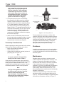
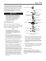
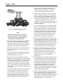
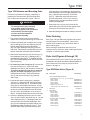
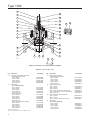
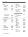
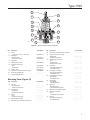
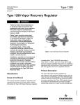
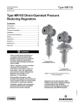
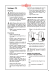
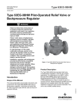
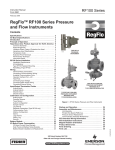
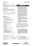
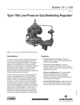
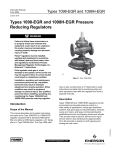
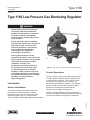
Type 1190
Instruction Manual
Form 5307
April 2012
Type 1190 Low-Pressure Gas Blanketing Regulator
!
WARNING
Failure to follow these instructions or
to properly install and maintain this
equipment could result in an explosion,
fire and/or chemical contamination
causing property damage and personal
injury or death.
Fisher® regulators must be installed,
operated, and maintained in accordance
with federal, state, and local codes,
rules and regulations, and Emerson
Process Management Regulator
Technologies, Inc. (Regulator
Technologies) instructions.
If the regulator vents gas or a leak
develops in the system, service to the unit
may be required. Failure to correct trouble
could result in a hazardous condition.
Installation, operation, and
maintenance procedures performed
by unqualified personnel may result
in improperadjustment and unsafe
operation. Either condition may result
in equipment damage or personal injury.
Use qualified personnel when installing,
operating, and maintaining the
Type 1190 regulator.
Introduction
Scope of the Manual
Figure 1. Type 1190 Low-Pressure Gas Blanketing Regulator
Product Description
The Type 1190 low-pressure gas blanketing regulator
is a pilot-operated, pressure reducing regulator with
a supply pressure regulator. This regulator is used
for extremely accurate pressure control on very
low-pressure gas blanketing systems. This regulator
helps to control emissions and provides protection
against any contamination from atmospheric
conditions by providing a flushing action.
The Type 1190 gas blanketing regulator maintains a
positive vessel pressure thereby reducing the possibility
of vessel wall collapse during pump-out operations.
D101644X012
This manual provides installation, startup, and
maintenance instructions and parts ordering
information for the Type 1190 low-pressure gas
blanketing regulator (Figure 1) complete with
Type Y191A pilot and Type 95H supply pressure regulator.
W7428
www.fisherregulators.com
Type 1190
Specifications
Specifications for a given regulator as it originally comes from the factory are stamped on nameplates located on
the actuator and main valve body, while the pilot outlet pressure range appears on the pilot spring case closing cap.
Body Sizes(1)
Main Valve Orifice Diameters and Travels
BODY SIZES,
NPS
END CONNECTION STYLE
WCC Steel or
Cast Iron
CF8M Stainless Steel
DN
1, 2
25, 50
NPT, CL125 FF, or
CL250 RF flanged
NPT, SWE, BWE,
CL150 RF, CL300 RF, CL600
RF, or PN 16 / 25 / 40 flanged
3, 4, 6
80, 100,
150
CL125 FF, or
CL250 RF flanged
BWE, CL150 RF, CL300 RF,
CL600 RF, or PN 16 flanged
8 x 6,
12 x 6
200 x 150,
300 x 150
----
BWE, CL150 RF, CL300 RF,
CL600 RF, or PN 25 flanged
Maximum Main Valve Inlet Pressures(2)
400 psig / 27.6 bar
Maximum Operating Inlet Pressures(2)
200 psig / 13.8 bar with cast iron construction
or 300 psig / 20.7 bar with a steel or stainless
steel construction
Maximum Outlet (Casing) Pressure(2)
75 psig / 5.2 bar
Maximum Operating Outlet Pressure to Avoid
Internal Parts Damage(2)
75 psig / 5.2 bar
Outlet Pressure Ranges (Type Y191A Pilot)(2)
See Table 1
Flow Coefficients for Relief Valve Sizing
See Table 2
Maximum and Minimum Differential Pressures
BODY SIZES
See Table 3
ORIFICE
DIAMETER
Standard
TRAVEL
Restricted Capacity
Percent
NPS
1
DN
25
Inch
1-5/16
mm
33
Inch
3/4
mm
19
2
50
2-3/8
60
1-1/8
29
3
80
3-3/8
4
100
4-3/8
6, 8 x 6, 150, 200 x 150,
7-3/16
12 x 6
300 x 150
86
111
1-1/2
2
38
51
---30
70
40
40
183
2
51
40
Travel
Inch mm
---- ---3/8 95
5/8 16
7/8 22
1
25
1
Supply Pressure Settings Required for the
Type 95H Supply Pressure Regulator
See Table 4
Pressure Registration
External
Main Valve Flow Characteristic
Linear
Temperature Capabilities(2)
Nitrile (NBR): -20 to 180°F / -29 to 82°C
Fluorocarbon (FKM): 40 to 300°F / 4 to 149°C
Ethylenepropylene (EPDM):
 -20 to 275°F / -29 to 135°C
Perfluoroelastomer (FFKM):
 -20 to 300°F / -29 to 149°C
Approximate Weights
NPS 1 / DN 25: 85 pounds / 39 kg
NPS 2 / DN 50: 100 pounds / 45 kg
NPS 3 / DN 80: 145 pounds / 66 kg
NPS 4 / DN 100: 195 pounds / 88 kg
NPS 6 / DN 150: 380 pounds / 172 kg
NPS 8 x 6 / DN 200 x 150: 740 pounds / 336 kg
NPS 12 x 6 / DN 300 x 150: 1265 pounds / 574 kg
1. End connections for other than U.S. standard can usually be provided; consult your local Sales Office.
2. The pressure/temperature limits in this Instruction Manual and any applicable standard or code limitation should not be exceeded.
Table 1. Outlet Pressure Ranges (Type Y191A Pilot)
OUTLET PRESSURE RANGE
(1)
Inches w.c.
mbar
SPRING
PART NUMBER
SPRING
COLOR
0.25 to 2.5(2)
2 to 7(2)
5 to 16
0.6 to 6(2)
5 to 17(2)
12 to 40
1B558527052
1B653827052
1B653927022
0.5 to 1.2 psig
1.1 to 2.5 psig
2.5 to 4.5 psig
4.5 to 7.0 psig
34 to 83
76 to 172
172 mbar to 0.31 bar
0.31 to 0.48 bar
1B537027052
1B537127022
1B537227022
1B537327052
SPRING WIRE DIAMETER
SPRING FREE LENGTH
Inch
mm
Inch
mm
Orange
Red
Unpainted
0.072
0.085
0.105
1.83
2.16
2.67
3.78
3.63
3.75
96.0
92.1
95.3
Yellow
Green
Light blue
Black
0.114
0.156
0.187
0.218
2.90
3.96
4.75
5.54
4.19
4.06
3.94
3.98
106
103
100
101
1. Outlet pressure ranges based on pilot being installed with the spring case pointed down.
2. Do not use Fluorocarbon (FKM) diaphragm with this spring at diaphragm temperatures lower than 60°F / 16°C.
2
25
Type 1190
TYPE 1098-EGR
MAIN VALVE
TYPE 95H SUPPLY
REGULATOR
CONTROL LINE
TYPE Y191A PILOT
SETPOINT
ADJUSTMENT
FIXED
RESTRICTION
DOWNSTREAM
BLEED LINE
B2328_3
INLET PRESSURE
OUTLET PRESSURE
GAS BLANKETING
PRESSURE
LOADING PRESSURE
PILOT SUPPLY PRESSURE
ATMOSPHERIC PRESSURE
Figure 2. Type 1190 Low-Pressure Gas Blanketing Regulator Operational Schematic
Principle of Operation
The Type 1190 gas blanketing regulator reduces
a high-pressure inert gas to maintain a positive
low-pressure gas blanket over a stored liquid
while liquid is being pumped out of the tank. Also,
when the tank suddenly cools causing tank vapors
to condense, the Type 1190 regulator replaces the
condensing vapors with an inert gas to prevent the
internal tank pressure from decreasing. In both
cases, a positive tank pressure prevents outside air
from entering the vessel preventing contamination
and reducing the possibility of atmospheric pressure
collapsing the vessel.
The Type 1190 regulator is pilot-operated to respond to
slight decreases in internal tank pressure by throttling
open to increase the flow rate of inert gas into the vessel.
When the vessel’s liquid level has been lowered to the
desired point and the vapor pressure re-established, the
Type 1190 regulator throttles closed.
The Type 1190 regulator utilizes a Type 1098-EGR
main valve actuator (Type EGR main valve and
Type 1098 actuator), a Type Y191A sensing pilot, and
a Type 95H supply pressure regulator. The Type Y191A
pilot uses the high-pressure inlet gas, reduced by the
Type 95H supply pressure regulator, as loading pressure
to operate the Type 1098-EGR main valve actuator. The
outlet or vessel pressure is sensed through a control line
on the Type 1098-EGR main valve actuator and also on
the Type Y191A pilot diaphragm.
When the liquid level is decreased and vessel
pressure decreases below the pilot outlet pressure
setting, the spring force on the pilot diaphragm
opens the pilot valve plug, allowing additional loading
pressure on the main valve actuator diaphragm. The
loading pressure opens the main valve plug to supply
the required flow of gas to the vessel.
When downstream demand has been satisfied, outlet
pressure tends to increase slightly, acting on the pilot
and main valve diaphragms. When the outlet pressure
exceeds the pilot outlet pressure setting, the pilot
diaphragm moves to close the pilot valve plug. The
loading pressure reduces by exhausting downstream
through the fixed restriction, allowing the main valve
spring to close the main valve plug. The combination
of main valve spring force and main valve plug
unbalance provides positive shutoff of the valve plug.
3
Type 1190
Table 2. Flow Coefficients
PIPING STYLE
Line Size Equals Body Size Piping
BODY SIZES
Linear Cage
Cg
Drilled Hole Whisper Trim™ Cage
Cv
C1
Regulating Wide-Open Regulating Wide-Open
Cg
Cv
Regulating Wide-Open Regulating Wide-Open
C1
NPS
DN
1
25
600
632
16.8
17.7
35.7
576
607
16.7
17.6
34.5
2
50
2280
2400
63.3
66.7
36.0
1970
2080
54.7
57.8
36.0
3
80
4630
4880
132
139
35.1
3760
3960
107
113
35.0
4
100
7320
7710
202
213
36.2
6280
6610
180
190
34.8
6
150
12,900
13,600
397
418
32.5
9450
9950
295
310
32.0
8x6
200 x 150
18,480
19,450
578
608
32.0
10,660
11,220
305
321
35.0
12 x 6
300 x 150
21,180
22,290
662
697
32.0
11,050
11,630
316
332
35.0
2:1 Line Size to Body Size Piping
BODY SIZES
Standard Linear Cage
Cg
Drilled Hole Whisper Trim™ Cage
Cv
C1
Regulating Wide-Open Regulating Wide-Open
Cg
Cv
Regulating Wide-Open Regulating Wide-Open
C1
NPS
DN
1
25
568
598
17.2
18.1
33.0
529
557
15.6
16.4
34.0
2
50
2050
2160
59.6
62.8
34.4
1830
1930
52.3
55.1
35.0
3
80
4410
4650
128
135
34.4
3630
3830
106
110
34.2
4
100
6940
7310
198
209
35.0
6020
6340
171
180
35.2
6
150
12,100
12,800
381
404
31.7
9240
9730
291
306
31.7
8x6
200 x 150
17,370
18,280
543
571
32.0
10,020
10,550
286
301
35.0
12 x 6
300 x 150
19,900
20,950
622
655
32.0
10,380
10,930
297
312
35.0
Table 3. Maximum and Minimum Differential Pressures for Main Valve Spring Selection
BODY SIZES
NPS
1
2
3
4
6,
8 x 6,
12 x 6
4
DN
25
50
80
100
150,
200 x 150,
300 x 150
MAIN VALVE
SPRING PART
NUMBER
SPRING
COLOR
14A9687X012
Green
14A9680X012
Blue
14A9679X012
Red
14A6626X012
Green
14A6627X012
Blue
14A6628X012
Red
14A6629X012
14A6630X012
MAXIMUM ALLOWABLE
DIFFERENTIAL PRESSURE
MINIMUM DIFFERENTIAL
PRESSURE REQUIRED
FOR FULL STROKE
psig
bar
psig
bar
60
4.1
2.5
0.17
125
8.6
4
0.28
300 or body rating
limit, whichever is lower
20.7 or body rating limit,
whichever is lower
5
0.34
60
4.1
3
0.21
125
8.6
5
0.34
300 or body rating
limit, whichever is lower
20.7 or body rating limit,
whichever is lower
10
0.69
Green
60
4.1
4
0.28
Blue
125
8.6
6
0.41
14A6631X012
Red
300 or body rating
limit, whichever is lower
20.7 or body rating limit,
whichever is lower
11
0.76
14A6632X012
Green
60
4.1
5
0.34
14A6633X012
Blue
125
8.6
8
0.55
14A6634X012
Red
300 or body rating
limit, whichever is lower
20.7 or body rating limit,
whichever is lower
13
0.90
14A9686X012
Green
60
4.1
9.5
0.66
14A9685X012
Blue
125
8.6
14
1.0
Red
300 or body rating
limit, whichever is lower
20.7 or body rating limit,
whichever is lower
19
1.3
15A2615X012
Type 1190
Table 4. Supply Pressure Settings Required for the Type 95H Regulator
SUPPLY PRESSURE
TYPE EGR
SPRING
COLOR
BODY SIZES
NPS
1
DN
25
2
50
3
80
4
100
6, 8 x 6,
12 x 6
150, 200 x 150,
300 x 150
Type Y191A Spring Color
Orange
Red
Unpainted
Yellow
Green
Light Blue
Black
psig
bar
psig
bar
psig
bar
psig
bar
psig
bar
psig
bar
psig
bar
Green
6
0.41
6
0.41
6
0.41
7
0.48
8
0.55
11
0.76
13
0.90
Blue
7
0.48
7
0.48
7
0.48
8
0.55
10
0.69
13
0.90
14
1.0
Red
8
0.55
8
0.55
8
0.55
9
0.62
11
0.76
14
0.97
15
1.0
Green
6
0.41
6
0.41
6
0.41
7
0.48
9
0.62
12
0.83
13
0.90
Blue
8
0.55
8
0.55
8
0.55
9
0.62
11
0.76
14
0.97
15
1.0
Red
13
0.90
13
0.90
13
0.90
14
1.0
16
1.1
19
1.3
20
1.4
Green
7
0.48
7
0.48
7
0.48
8
0.55
10
0.69
13
0.90
14
1.0
Blue
9
0.62
9
0.62
9
0.62
10
0.69
12
0.83
15
1.0
16
1.1
Red
14
1.0
14
1.0
14
1.0
15
1.0
17
1.2
20
1.4
21
1.5
Green
8
0.55
8
0.55
8
0.55
9
0.62
11
0.76
14
1.0
15
1.0
Blue
11
0.76
11
0.76
11
0.76
12
0.83
14
1.0
17
1.2
18
1.3
Red
16
1.1
16
1.1
16
1.1
17
1.2
19
1.3
22
1.5
23
1.6
Green
13
0.90
13
0.90
13
0.90
14
1.0
15
1.0
18
1.2
20
1.4
Blue
17
1.2
17
1.2
17
1.2
18
1.2
20
1.4
23
1.6
24
1.7
Red
22
1.5
22
1.5
22
1.5
23
1.6
25
1.7
28
1.9
29
2.0
1. The pressures shown in the table are the minimum supply pressures required by the pilot. If the inlet pressure is less than shown, an external pilot supply is necessary.
Installation and Startup
!
WARNING
Personal injury, equipment damage, or
leakage due to escaping accumulated gas
or bursting of pressure-containing parts
may result if this gas blanketing regulator
is overpressured or is installed where
service conditions could exceed the limits
given in the Specifications section and
on the appropriate nameplate, or where
conditions exceed any ratings of the
adjacent piping or piping connections.
To avoid such injury or damage, provide
pressure-relieving or pressure-limiting
devices (as required by Title 49, Part 192,
of the U.S. Code of Federal Regulations;
by the National Fuel Gas Code Title 54 of
the National Fire Codes of the National
Fire Protection Association; or by other
applicable codes) to prevent service
conditions from exceeding those limits.
Additionally, physical damage to the
gas blanketing regulator could result in
personal injury and property damage due
to escaping accumulated gas. To avoid
such injury and damage, install the gas
blanketing regulator in a safe location.
Note
On the Type EGR main valve, a normal
pressure drop assists shutoff. Therefore,
leakage (backflow) may result during any
reverse pressure drop condition.
1. Use qualified personnel when installing, operating,
and maintaining regulators. Before installing,
inspect the main valve, actuator, pilot, supply
pressure regulator, and tubing for any shipment
damage or foreign material that may have collected
during crating and shipment. Make certain the
body interior is clean and the pipelines are free of
foreign material. Apply pipe compound only to the
external pipe threads with a threaded body, or use
suitable line gaskets and good bolting practices
with a flanged body.
Note
The Type 1190 gas blanketing regulator
should be installed as shown in Figure 1
so that flow through the Type 1098-EGR
main valve actuator matches the flow
arrow attached to the valve body.
!
WARNING
A regulator may vent some gas to
the atmosphere. In hazardous or
flammable gas service, vented gas
5
Type 1190
may accumulate, and cause personal
injury, death, or property damage due
to fire or explosion. Vent a regulator
in hazardous gas service to a remote,
safe location away from air intakes or
any hazardous location. The vent line
or stack opening must be protected
against condensation or clogging.
2. To keep the pilot spring case vent assembly
from plugging or the spring case from collecting
moisture, corrosive chemicals, or other foreign
material, point the vent down or otherwise protect
it. For proper operation, install the Type Y191A
pilot with the spring case barrel pointed down as
shown in Figure 1. To remotely vent a Type Y191A,
remove the vent assembly (key 26, Figure 8) and
install obstruction-free tubing or piping into the
1/4 NPT vent tapping. Provide protection on a
remote vent by installing a screened vent cap into
the end of the vent pipe.
BODY FLANGE
CAGE SCREWS INTO
BODY FLANGE
SEAT RING SCREWS
INTO CAGE
W3012-1
Figure 3. Trim Package Removal
Prestartup Considerations
The only adjustment necessary on a Type 1190
regulator is the pilot control spring pressure setpoint.
Turning the adjusting screw of the Type Y191A pilot
clockwise into the spring case increases the spring
compression and pressure setting. Turning the
adjusting screw counterclockwise decreases the
spring compression and pressure setting.
Before beginning the startup procedure in this section,
make sure the following conditions are in effect:
Shutdown
3. Attach a 3/4 NPT downstream pressure control
line to the tank using a straight run of pipe. Connect
the other end of the control line to the Type 1098
actuator bonnet connection (see Figure 2).
• Block valves isolate the regulator
• Hand valves are closed
• Gauges may be installed (if required) in place of
pipe plugs (key 52, Figure 10)
Note
For proper operation, the Type 95H is
factory set to the values in Table 4.
Slowly open the upstream block valve introducing
pressure into the Type 1190 gas blanketing regulator.
Slowly open the downstream block valve. The
regulator will immediately begin to operate. Monitor
the blanket pressure to ensure correct operation.
Note
The Type 1190 regulator was preset at
the factory at the customer’s specified
pressure or the mid-range of the
Type Y191A pilot. The outlet pressure
range of the Type Y191A pilot is stamped
on the spring case closing cap.
6
Installation arrangements vary, but in any installation
it is important to open and close valves slowly and
to close the upstream block valve first when shutting
down the system.
Maintenance
Regulator parts are subject to normal wear and
must be inspected and replaced as necessary. The
frequency of inspection and replacement of parts
depends upon the severity of the service conditions
or the requirements of local, state, and federal
regulations. Due to the care Regulator Technologies
takes in meeting all manufacturing requirements
(heat treating, dimensional tolerances, etc.), use
only replacement parts manufactured or furnished by
Regulator Technologies.
The stem O-rings on the Type 1098 actuator can be
lubricated annually, using the grease fitting (key 28,
Figure 7). Line pressure leakage or unexpected grease
extrusion from the actuator vent (key 27, Figure 7)
Type 1190
during normal operation indicates stem O-ring damage.
All O-rings, gaskets, and seals should be lubricated with
a good grade of general-purpose grease and installed
gently rather than forced into position. Be certain that
the nameplates are updated to accurately indicate
any field changes in equipment, materials, service
conditions, or pressure settings.
INDICATOR PROTECTOR (KEY 19)
INDICATOR SCALE (KEY 18)
FLANGE NUT (KEY 22)
!
WARNING
HEX NUT (KEY 8)
INDICATOR FITTING (KEY 5)
O-RING RETAINER (KEY 6)
To avoid personal injury resulting from
sudden release of pressure, isolate the
pilot or regulator from all pressure and
cautiously release trapped pressure
from the pilot or regulator before
attempting disassembly.
STEM O-RING (KEY 7)
INDICATOR FITTING
O-RING (KEY 21)
SPRING (KEY 9)
E-RING (KEY 23)
INDICATOR STEM (KEY 10)
SPRING SEAT (KEY 28)
Type EGR Main Valve
PIPE PLUG (KEY 31)
BODY FLANGE (KEY 2)
Replacing Quick-Change Trim Package
Perform this procedure if replacing the entire trim package
(Figure 3). Key numbers for both the complete main valve
and its trim package are referenced in Figure 6.
VALVE PLUG (KEY 16)
UPPER SEAL (KEY 15)
Note
All disassembly, trim change, and
reassembly steps in this section can be
performed with the Type EGR main valve
in the pipeline.
1. Disconnect the supply pressure tubing from the
top of the Type 1098-EGR main valve actuator.
Remove the cap screws or stud bolts (key 3). Pry
the body flange (key 2) loose from the valve body
(key 1), and lift out the trim package (Figure 3).
2. Perform any required inspection, cleaning, or
maintenance on the exposed surfaces of the valve
body or trim package. Replace the gasket (key 4)
and cage O-ring (key 17) as necessary.
3. On a pre-built replacement trim package, check
indicator zeroing by unscrewing the indicator
protector (key 19) and seeing if the flange of the
flange nut (key 22) lines up evenly with the bottom
marking on the indicator scale (key 18). If not,
remove the indicator scale and separate the flange
nut and hex nut (key 8). Hold the indicator scale
against the indicator fitting (key 5) with the scale
base resting against the shoulder of the fitting,
and turn the indicator nut to align its flange with
the bottom scale marking. Then lock both nuts
against each other, and install the indicator scale
and protector.
CAGE (KEY 11)
CAGE O-RING (KEY 17)
PORT SEAL (KEY 12)
SEAT RING (KEY 13)
W3116
Figure 4. Exploded View of Full-Capacity Trim
Package Assembly
4. Lightly coat the cage seating surfaces of the valve
body web and the body flange seating surfaces of
the valve body neck with a good grade of general
purpose grease. Install the trim package, and
secure it evenly with the cap screws or stud bolts.
No particular trim package orientation in the body
is required.
5. Remove the pipe plug (key 31) from the Type EGR
main valve body flange (key 2) and reconnect the
Type 95H supply pressure tubing and fittings as
shown in Figure 10.
Replacing Trim Parts
Perform this procedure if inspecting, cleaning, or
replacing individual parts in a trim package. Key
numbers are referenced in Figure 6. An exploded view
of a standard full-capacity trim package only is shown
in Figure 4.
7
Type 1190
(key 8). Insert a screwdriver through the O-ring
retainer (key 6) to remove the stem O-ring
without removing the retainer. If necessary,
unclip the E-ring from the indicator stem.
6. Replace and lubricate parts, such as the gasket
(key 4) and cage O-ring (key 17), as necessary.
If the port seal (key 12) and upper seal (key 15)
were removed, install them in their retaining slots
with the grooved sides facing out. Also for ease
of installation, lubricate any other surfaces as
necessary. No further main valve maintenance is
necessary if only the indicator fitting and attached
parts were removed.
W2772-1
Figure 5. Seat Ring/Cage Removal or Installation
Using Body as Holding Fixture
Note
Access to the spring (key 9), indicator
fitting O-ring (key 21) or travel indicator
parts in step 1 can be gained without
removing the body flange (key 2).
1. Remove the indicator fitting (key 5) and attached
parts. Disconnect the supply pressure tubing
and fittings from the top of the Type 1098-EGR
main valve. Proceed to step 5 if only performing
maintenance on the fitting or attached parts.
2. Remove the cap screws or stud bolts (key 3) and
pry the body flange (key 2) loose from the valve
body (key 1).
3. Use the valve body as a holding fixture if desired.
Flip the body flange over, and anchor it on the
valve body as shown in Figure 5.
4. To gain access to the port seal (key 12), upper
seal (key 15), or valve plug parts, unscrew the seat
ring (key 13) from the cage (key 11) and the cage
from the body flange (key 2). For leverage, insert
a wrench handle or similar tool into the seat ring
slots (Figure 5) and wrap a strap wrench around a
cage, or insert a soft bar through the windows of the
cage. Proceed to step 6 if no further maintenance
is necessary.
5. To replace the body flange (key 2) or gain access
to the spring (key 9), indicator stem (key 10),
stem O-ring (key 7), spring seat (key 28), or
E-ring (key 23), remove the indicator protector
(key 19) and indicator scale (key 18). Since
some compression is left in the spring, carefully
remove the flange nut (key 22) and hex nut
8
7. Insert the valve plug (key 16) into the body flange
(key 2), install the cage (key 11) plus upper seal
(key 15), and O-ring (key 17) into the body flange,
and then install the seat ring (key 13) plus port
seal (key 12) into the cage. Use the valve body
as a holding fixture during this step as shown in
Figure 5, and insert a wrench handle or similar
tool into the seat ring slots for leverage when
tightening the seat ring (key 13) and cage.
8. Remove the upsidedown body flange (key 2) if it
was anchored on the body (key 1). Lightly coat the
cage seating surfaces of the valve body web and
the body flange seating surfaces of the valve body
neck with a good grade of general-purpose grease.
Install the body flange on the body, and secure it
evenly with the cap screws or stud bolts (key 3).
9. Install the indicator fitting O-ring (key 21), stem
O-ring (key 7), and O-ring retainer (key 6) in the
indicator fitting (key 5). Orient the spring seat
(key 28) as shown in Figure 6, and attach it
with the E-ring (key 23) to the slotted end of the
indicator stem (key 10). Then install the
spring (key 9).
10. Being careful not to cut the stem O-ring (key 7) with
the stem threads, place the indicator fitting (key 5)
over the indicator stem (key 10) until resting on the
spring (key 9). Install the hex nut (key 8) and then
the flanged indicator nut (key 22) on the indicator
stem, pushing on the fitting if necessary to provide
sufficient stem thread exposure. To maintain
clearance for indicator part installation, draw up the
spring seat (key 28) by turning the hex nut down on
the stem until the threads bottom.
11. Install the indicator fitting (key 5) with attached parts
into the body flange (key 2). Back off the hex nut
(key 8) until the spring (key 9) completely closes the
valve plug (key 16) against the port seal (key 12) and
upper seal (key 15), as indicated by stem threads
showing between this nut and the fitting.
Type 1190
12. Hold the indicator scale (key 18) against the
fitting with the scale base resting against the
shoulder of the fitting, and turn the flanged
indicator nut (key 22) until its flange is aligned
with the bottom scale marking. Then lock both
nuts against each other, and install the indicator
scale and protector (key 19).
Type Y191A Pilot
Key numbers are referenced in Figure 8.
!
WARNING
To avoid personal injury resulting from
sudden release of pressure, isolate the
pilot from all pressure and cautiously
release trapped pressure from the pilot or
regulator before attempting disassembly.
Body Area
This procedure is for gaining access to the disk
assembly, orifice, and body seal O-ring.
1. Remove the cap screws (key 2) and separate the
lower casing assembly (key 4) from the body
(key 1).
2. Remove and inspect the body seal O-ring (key 11)
and the backup ring (key 49). See the expanded
view of the body area in Figure 8.
3. Inspect and replace the orifice (key 5) if necessary.
Protect the orifice seating surface during disassembly
and assembly. Sparingly lubricate the threads of
the orifice with a good grade of grease and install
with 29 to 38 foot-pounds / 39 to 51 N•m of torque.
4. To replace the disk assembly (key 13) or the throat
seal O-ring (key 31), remove the cotter pin (key 15).
5. To inspect the throat seal O-ring (key 31), remove
the machine screw (key 33). Replace if necessary
and reassemble.
6. Install the disk assembly (key 13) and secure it with
the cotter pin (key 15).
7. Place the backup ring (key 49) into the body
(key 1). Then place the body seal O-ring (key 11)
into the body.
8. Place the lower casing assembly (key 4) on the
body (key 1) and secure it with the cap screws
(key 2).
Diaphragm and Spring Case Area
This procedure is for gaining access to the spring,
diaphragm, lever assembly, and stem.
To Change the Control Spring:
1. Remove the closing cap (key 22), and release all
the compression from the spring (key 6) by turning
the adjusting screw (key 35) counterclockwise.
2. Change the spring (key 6) to match the desired
outlet pressure range.
3. Replace the adjusting screw (key 35).
4. Install a replacement closing cap gasket (key 25),
if necessary, and reinstall the closing cap (key 22).
5. If the outlet pressure range was changed, be sure
to change the stamped range on the nameplate.
To Disassemble and Reassemble Diaphragm Parts:
1. Remove the closing cap (key 22), and turn the
adjusting screw (key 35) counterclockwise to
remove the adjusting screw and the spring (key 6).
2. Remove the spring case hex nuts (key 23, not
shown), cap screws (key 24), and spring case
assembly (key 3).
3. Remove the diaphragm (key 10) and attached
parts by tilting them so that the pusher post (key 8)
slips off the lever assembly (key 16). To separate
the diaphragm from the attached parts, unscrew
the machine screw (key 38) from the pusher post.
4. Inspect the pusher post (key 8) and the connector
seal O-ring (key 50), replace if required.
5. Remove hex nut (key 21) to separate the diaphragm
(key 10) and attached parts.
6. To replace the lever assembly (key 16), remove the
machine screws (key 17). To replace the stem
(key 14), perform Body Area Maintenance steps 1
and 4, and pull the stem out of the guide insert
(key 18).
7. Install the stem (key 14) into the guide insert
(key 18) and then perform Body Area Maintenance
steps 6 through 8 as necessary.
8. Install the lever assembly (key 16) into the stem
(key 14) and secure the lever assembly with the
machine screws (key 17).
9
Type 1190
9. Install the parts on the pusher post in the order
listed below:
• Pusher post (key 8)
• Pusher post connector (key 40)
• Connector seal O-ring (key 50)
• Lower diaphragm head (key 51)
• Diaphragm (key 10)
• Diaphragm head (key 7)
• Hex nut (key 21)—Torque hex nut to
9 to 11 foot-pounds / 12 to 15 N•m to secure parts to the pusher post connector.
• Overpressure spring (key 39)
• Spring holder (key 37)
• Machine screw (key 38)
10. Insert and tighten the cap screw (key 38) with a
torque of 1 to 3 foot-pounds / 1.4 to 4.1 N•m to
secure the diaphragm parts to the pusher post
(key 8).
11. Install the assembled parts into the lower
diaphragm casing assembly (key 4). Make sure
that the lever assembly (key 16) fits in the pusher
post (key 8) and the holes in the diaphragm
(key 10) align with the holes in the diaphragm
casing assembly.
12. Install the spring case assembly (key 3) on
the lower casing assembly (key 4) so that the
vent assembly (key 26) is correctly oriented.
Secure the spring case assembly with the cap
screws (key 24) and hex nuts (key 23, not
shown) fingertight.
13. Insert the spring (key 6) into the spring case
assembly (key 3), followed by the adjusting
screw (key 35).
14. Turn the adjusting screw (key 35) clockwise until
there is enough spring force to provide proper slack
to the diaphragm (key 10). Use crisscross pattern
to tighten the cap screws (key 24) and hex nuts
(key 23, not shown) with 18 to 21 foot-pounds /
24 to 28 N•m of torque.
15. Install a replacement closing cap gasket (key 25)
if necessary, and then install the closing cap
(key 22).
Type 95H Supply Pressure Regulator
This section includes instructions for disassembly and
assembly of replacement parts. All key numbers refer
to Figure 9.
10
!
WARNING
To avoid personal injury resulting from
sudden release of pressure, isolate
the regulator from all pressure and
cautiously release trapped pressure
from the main valve, pilot, or supply
regulator before attempting disassembly.
1. Unscrew the valve plug guide (key 5) from the
body (key 1). The valve plug spring (key 10) and
the valve plug (key 4) will normally come out of
the body along with the valve plug guide.
2. Inspect the seating surface of the valve plug,
being sure that the composition surface (or
polished steel surface) of the valve plug is not
damaged. Replace if damaged.
3. Inspect the seating edge of the orifice (key 3).
If damaged, unscrew the orifice from the body
(key 1) and replace it with a new part. If no further
maintenance is required, reassemble the regulator
in the reverse of the above steps. When installing
the valve plug guide (key 5), coat the threads
and sealing surface with sealant to ensure an
adequate metal-to-metal seal.
4. To inspect the diaphragm (key 12) or other internal
parts, loosen the locknut (key 17) and turn the adjusting
screw (key 15) counterclockwise to remove all
spring compression.
5. Remove the diaphragm case cap screws (key 16)
and lift off the spring case (key 2). Remove the
upper spring seat (key 9) and regulator spring
(key 11). Remove the lower spring seat (key 8).
6. Remove the diaphragm (key 12) and examine for
damage. Replace if damaged.
7. With diaphragm removed, check to be sure the
pressure registration hole is completely open and
free of all obstructions.
8. Reassemble in reverse order of the previous
steps. Lubricate the upper spring seat (key 9)
and the exposed threads of the adjusting screw
(key 15). Before tightening cap screws (key 16)
be sure to install the adjusting screw, if completely
removed, and turn it down to obtain diaphragm slack.
This allows proper positioning of the diaphragm to
permit full travel of the valve plug (key 4). Complete
reassembly procedures and temporarily install a
gauge in place of the pipe plug (key 52, Figure 10).
Turn the adjusting screw to produce the desired
outlet pressure values shown in Table 4. Tighten the
locknut to maintain the desired setting.
Type 1190
Type 1098 Actuator and Mounting Parts
to prevent stem or O-ring damage, and secure the
lower diaphragm case to the upper diaphragm case
(key 1) with the cap screws (key 10) and nuts
(key 11). Tighten the cap screws and nuts to
24 to 30 foot-pounds / 32 to 41 N•m of torque.
Tighten evenly in a crisscross pattern to avoid
crushing the diaphragm.
Perform this procedure if changing, inspecting, or
replacing the actuator and/or pilot mounting parts.
Key numbers are referenced in Figures 7 and 10.
!
WARNING
To avoid personal injury resulting
from sudden release of pressure,
isolate the regulator from all pressure
and cautiously release trapped
pressure from the unit before
attempting disassembly.
1. The actuator and pilot may be removed and
replaced as a unit by disconnecting the control line.
2. Access to all internal parts except the stem O-rings
(key 6), bearings (key 56), and wiper ring (key 57)
may be gained without removing the bonnet
(key 3) or upper diaphragm case (key 2) from the
main valve. Disconnect the loading tubing (key 24)
and the control line connection from the actuator.
3. Remove the cap screws (key 10), hex nuts (key 11),
lower diaphragm case (key 1), diaphragm (key 7),
and diaphragm plate (key 8). To separate the stem
(key 12) from the diaphragm plate, remove the stem
cap screw (key 9).
4. To remove the case O-ring (key 5), unscrew the
four cap screws (key 4), remove the upper
diaphragm case (key 2), and remove the case O-ring.
To remove the stem O-rings (key 6), bearings
(key 56), and wiper ring (key 57), remove the
loading and control lines. Unscrew the bonnet
(key 3), and remove the wiper ring, bearings,
and O-rings.
5. Lubricate both stem O-rings (key 6), and wiper
ring (key 57). Install them with the stem bearings
(key 56) in the bonnet (key 3). Lubricate the case
O-ring (key 5), and install it in the bonnet. Line up
the holes in the upper diaphragm casing (key 2) and
the bonnet; insert and tighten the four cap screws
(key 4) to 24 to 30 foot-pounds / 32 to 41 N•m of
torque. Thread the bonnet into the main valve body.
6. Secure the diaphragm plate (key 8) to the stem
(key 12) with the stem cap screw (key 9). Lay the
entire diaphragm (key 7), diaphragm plate, and
stem assembly into the lower diaphragm case
(key 2) so the diaphragm convolution laps up over
the diaphragm plate according to Figure 7. Then
install the stem slowly up into the bonnet (key 3)
7. Grease the stem O-rings (key 6) through the
grease fitting (key 28) until excess grease starts
coming out the vent assembly (key 27).
8. Install the loading and control line tubing if removed.
Parts Ordering
Each Type 1190 gas blanketing regulator has a serial
number stamped on the nameplate. Refer to this
number when contacting your local Sales Office or
when ordering parts.
When ordering a replacement part, be sure to
reference the key number of each needed part and the
complete 11-character part number.
Parts List (Figures 6 through 10)
Parts marked NACE can be used for sour gas service
as detailed in the NACE International Standard MR0175.
Parts referenced in the parts list can be found in
Figures 6 through 10.
Type EGR Main Valve (Figure 6)
Key Description Part Number
Parts Kit, Nitrile (NBR) Elastomers
(included are keys 4, 7, 12, 15, 17, 21, 36, and 37)
NPS 1 / DN 25
NPS 2 / DN 50
NPS 3 / DN 80
NPS 4 / DN 100
NPS 6, 8 x 6, and 12 x 6 /
DN 150, 200 x 150, and 300 x 150
R63EGX00112
R63EGX00122
R63EGX00132
R63EGX00142
1
Valve Body
2
Body Flange
Cast iron, ENC
NPS 2 / DN 50
NPS 3 / DN 80
NPS 4 / DN 100
NPS 6 / DN 150
WCC steel, ENC, Heat-treated
NPS 1 / DN 25
NPS 2 / DN 50
NPS 3 / DN 80
NPS 4 / DN 100
NPS 6 / DN 150
R63EGX00162
See Table 5
25A3168X012
24A9034X012
25A2309X012
34A8172X012
24A6779X012
25A2254X012
25A2300X012
24A9032X012
34A7152X012
11
Type 1190
Table 5. Type EGR Main Valve Body Part Numbers (key 1)
BODY MATERIAL
BODY SIZES, NPS / DN
END CONNECTION
STYLE
1 / 25
2 / 50
3 / 80
4 / 100
6 / 150
8 x 6 / 200 x 150
NPT
34B7611X012
38A8845X012
-----------
-----------
-----------
-----------
CL125 FF
34B8630X012
38A8847X012
38A8851X012
38A8865X012
38A8875X012
-----------
CL250 RF
37B5950X012
38A8846X012
38A8850X012
38A8854X012
38A7110X012
-----------
NPT
37B5946X012
38A8848X012
-----------
-----------
-----------
-----------
SWE
GE05951X012
GE05958X012
-----------
-----------
-----------
-----------
CL150 RF
37B5947X012
38A8853X012
38A8872X012
38A8867X012
38A7115X012
GE05973X012
CL300 RF
37B5948X012
38A8849X012
38A8871X012
38A8869X012
38A8873X012
GE05974X012
CL600 RF
37B5949X012
38A8844X012
38A8852X012
38A8866X012
38A8874X012
GE05975X012
BWE (SCH 40)
GE05953X012
GE05957X012
GE05962X012
GE05967X012
GE05971X012
-----------
BWE (SCH 80)
GE05954X012
GE05959X012
GE05963X012
GE05968X012
GE05970X012
-----------
PN 16/25/40
GE05956X012
GE05960X012
GE05965X012
GE05969X012
GE05972X012
GE05977X012
Cast Iron
WCC Steel
WCC Steel
(NACE)
CF8M Stainless Steel
(NACE)
NPT
-----------
38A8848X022
-----------
-----------
-----------
-----------
CL150 RF
37B5947X022
38A8853X052
38A8872X062
38A8867X032
38A7115X022
GE05973X022
CL300 RF
37B5948X022
38A8849X022
38A8871X042
38A8869X022
38A8873X022
GE05974X022
CL600 RF
37B5949X022
38A8844X022
38A8852X032
38A8866X022
38A8874X022
GE05975X022
NPT
37B5946X032
38A8848X032
-----------
-----------
-----------
-----------
SWE
GE05951X022
GE05958X022
-----------
-----------
-----------
-----------
CL150 RF
37B5947X032
38A8853X072
38A8872X052
38A8867X042
38A7115X032
-----------
CL300 RF
37B5948X032
38A8849X032
38A8871X052
38A8869X032
38A8873X032
-----------
CL600 RF
37B5949X032
38A8844X032
38A8852X042
38A8866X032
38A8874X032
-----------
BWE (SCH 40)
GE05953X022
GE05957X022
GE05962X022
GE05967X022
GE05971X022
GE05976X022
BWE (SCH 80)
GE05954X022
GE05959X022
GE05963X022
GE05968X022
GE05970X022
-----------
PN 16/25/40
GE05956X022
GE05960X022
GE05965X022
GE05969X022
GE05972X022
-----------
Type EGR Main Valve (Figure 6)
Key Description Part Number
2
Body Flange (continued)
CF8M stainless steel, ENC,
Heat-treated (NACE) (continued)
NPS 1 / DN 25
NPS 2 / DN 50
NPS 3 / DN 80
NPS 4 / DN 100
NPS 6 / DN 150
3
Cap Screw, Zinc-plated steel
(use with cast iron or steel bodies)
NPS 1 / DN 25 (4 required) NPS 2 / DN 50 (8 required) NPS 3 / DN 80 (8 required) NPS 4 / DN 100 (8 required) NPS 6 / DN 150 (12 required) Key Description 24A6779X062
25A2254X082
25A2300X122
24A9032X042
34A7152X052
1R281124052
1A453324052
1A454124052
1A485724052
1U513124052
Stud Bolt, Steel (use with stainless steel bodies)
NPS 1 / DN 25 (4 required) NPS 2 / DN 50 (8 required) NPS 3 / DN 80 (8 required) NPS 4 / DN 100 (8 required) NPS 6 / DN 150 (12 required) 1R284835222
1K242935222
1A378135222
1R369035222
1A365635222
4* Gasket, Composition
NPS 1 / DN 25
NPS 2 / DN 50
NPS 3 / DN 80
NPS 4 / DN 100
NPS 6 / DN 150
14A6785X012
14A5685X012
14A5665X012
14A5650X012
14A6984X012
*Recommended spare part
Kalrez® is a mark owned by E.I. du Pont Nemours and Co.
12
Part Number
5 Lower Indicator Fitting
Plated steel
NPS 1 / DN 25
NPS 1 / DN 25 (NACE) NPS 2, 3, and 4 / DN 50, 80, and 100
NPS 6 / DN 150 (NACE) 316 Stainless steel
NPS 2, 3, and 4 / DN 50, 80, and 100 (NACE) T21117T0012
T21117T0022
T21107T0012
T21120T0012
6
T14276T0012
O-ring Retainer, 416 Stainless steel (NACE) T21107T0022
7* Stem O-Ring
Nitrile (NBR)
Fluorocarbon (FKM)
Kalrez® Perfluoroelastomer (FFKM)
Ethylenepropylene (EPDM)
1E472706992
1N430406382
1D6875X0082
1D6875X0092
8
1A662228992
Hex Nut, Plated steel 9 Spring
Steel
60 psi / 4.1 bar maximum drop, Green
NPS 1 / DN 25
NPS 2 / DN 50
NPS 3 / DN 80
NPS 4 / DN 100
NPS 6 / DN 150
125 psi / 8.6 bar maximum drop, Blue
NPS 1 / DN 25
NPS 2 / DN 50
NPS 3 / DN 80
NPS 4 / DN 100
NPS 6 / DN 150
14A9687X012
14A6626X012
14A6629X012
14A6632X012
14A9686X012
14A9680X012
14A6627X012
14A6630X012
14A6633X012
14A9685X012
Type 1190
Key Description 9 Spring (continued)
400 psi / 27.6 bar maximum drop, Red
NPS 1 / DN 25
NPS 2 / DN 50
NPS 3 / DN 80
NPS 4 / DN 100
NPS 6 / DN 150
Inconel® X750 (NACE)
60 psi / 4.1 bar maximum drop, Green
NPS 1 / DN 25
NPS 2 / DN 50
NPS 3 / DN 80
NPS 4 / DN 100
NPS 6 / DN 150
125 psi / 8.6 bar maximum drop, Blue
NPS 1 / DN 25
NPS 2 / DN 50
NPS 3 / DN 80
NPS 4 / DN 100
NPS 6 / DN 150
400 psi / 27.6 bar maximum drop, Red
NPS 1 / DN 25
NPS 2 / DN 50
NPS 3 / DN 80
NPS 4 / DN 100
NPS 6 / DN 150 10 Indicator Stem
Stainless steel
NPS 1 / DN 25
NPS 2 / DN 50
NPS 3 / DN 80
NPS 4 / DN 100
NPS 6 / DN 150
316 Stainless steel (NACE)
NPS 1 / DN 25
NPS 2 / DN 50
NPS 3 / DN 80
NPS 4 / DN 100
NPS 6 / DN 150
11 Cage
Linear, CF8M Stainless steel (NACE)
NPS 1 / DN 25
NPS 2 / DN 50
NPS 3 / DN 80
NPS 4 / DN 100
NPS 6 / DN 150
Whisper TrimTM Cage
416 Stainless steel
NPS 1 / DN 25
NPS 2 / DN 50
NPS 3 / DN 80
NPS 4 / DN 100
NPS 6 / DN 150
316 Stainless steel (NACE)
NPS 1 / DN 25
NPS 2 / DN 50
NPS 3 / DN 80
NPS 4 / DN 100
NPS 6 / DN 150
316 Stainless Steel, 55% Capacity
NPS 2 / DN 50
Quick Open
Cast Iron
NPS 1 / DN 25
NPS 2 / DN 50
NPS 3 / DN 80
NPS 4 / DN 100
Steel
NPS 6 / DN 150
*Recommended spare part
Kalrez® is a mark owned by E.I. du Pont Nemours and Co.
Inconel® is a mark owned by Special Metals Corporation.
Part Number
14A9679X012
14A6628X012
14A6631X012
14A6634X012
15A2615X012
11B6769X012
16A5501X012
16A5503X012
16A5506X012
16A5510X012
12B8326X012
16A5995X012
16A5996X012
16A5997X012
16A5999X012
10B1882X012
16A5499X012
16A5500X012
16A5998X012
16A6000X012
T14311T0012
T14275T0012
T14312T0012
T14313T0012
T14314T0012
T14311T0022
T14275T0022
T14312T0022
T14313T0022
T14314T0022
34B4136X012
34B5838X012
34B5839X012
34B5840X012
34B5841X012
24A2043X012
24A5707X012
24A5708X012
24A5709X012
24A8174X012
24A2043X022
24A5707X022
24A5708X042
24A5709X022
24A8174X022
37B7874X022
37A7211X012
37A7212X012
37A7213X012
37A7214X012
37A7215X022
Key Description Part Number
12* Port Seal
Nitrile (NBR) (standard)
NPS 1 / DN 2514A6788X012
NPS 2 / DN 5024A5673X012
NPS 3 / DN 8024A5658X012
NPS 4 / DN 10024A5643X012
NPS 6 / DN 15014A8175X012
Fluorocarbon (FKM)
NPS 1 / DN 2514A8186X012
NPS 2 / DN 5025A7412X012
NPS 3 / DN 8025A7375X012
NPS 4 / DN 10025A7469X012
NPS 6 / DN 15014A6996X012
Kalrez® Perfluoroelastomer (FFKM)
NPS 1 / DN 2514A6788X042
NPS 2 / DN 5024A5673X082
NPS 3 / DN 8024A5658X052
NPS 4 / DN 10024A5643X032
NPS 6 / DN 15014A8175X042
Ethylenepropylene (EPDM)
NPS 1 / DN 2514A6788X022
NPS 2 / DN 5024A5673X062
NPS 3 / DN 8024A5658X062
NPS 4 / DN 10024A5643X052
NPS 6 / DN 15014A8175X022
13* Seat Ring
416 Stainless steel
NPS 1 / DN 25, 1-5/16-inch / 33 mm orifice NPS 2 / DN 50, 2-3/8-inch / 60 mm orifice
NPS 3 / DN 80, 3-3/8-inch / 86 mm orifice
NPS 4 / DN 100, 4-3/8-inch / 111 mm orifice NPS 6 / DN 150, 7-3/16-inch / 183 mm orifice
NPS 8 x 6 / DN 200 x 150,
7-3/16-inch / 183 mm orifice
316 Stainless steel (NACE)
NPS 1 / DN 25, 1-5/16-inch / 33 mm orifice
NPS 2 / DN 50, 2-3/8-inch / 60 mm orifice
NPS 3 / DN 80, 3-3/8-inch / 86 mm orifice
NPS 4 / DN 100, 4-3/8-inch / 111 mm orifice
NPS 6 / DN 150, 7-3/16-inch / 183 mm orifice
NPS 8 x 6 / DN 200 x 150,
7-3/16-inch / 183 mm orifice
15* Upper Seal
Nitrile (NBR) (standard)
NPS 1 / DN 25
NPS 2 / DN 50
NPS 3 / DN 80
NPS 4 / DN 100
NPS 6 / DN 150
Fluorocarbon (FKM)
NPS 1 / DN 25
NPS 2 / DN 50
NPS 3 / DN 80
NPS 4 / DN 100
NPS 6 / DN 150
Kalrez® Perfluoroelastomer (FFKM)
NPS 1 / DN 25
NPS 2 / DN 50
NPS 3 / DN 80
NPS 4 / DN 100
NPS 6 / DN 150
Ethylenepropylene (EPDM)
NPS 1 / DN 25
NPS 2 / DN 50
NPS 3 / DN 80
NPS 4 / DN 100
NPS 6 / DN 150
24A6781X012
24A5670X012
24A5655X012
24A5640X012
24A6989X012
38A4216X012
24A6781X022
24A5670X022
24A5655X022
24A5640X022
24A6989X022
38A4216X022
14A6789X012
24A5674X012
24A5659X012
24A5644X012
14A8176X012
14A8187X012
25A7413X012
25A7376X012
25A7468X012
14A8185X012
14A6789X042
24A5674X082
24A5659X052
24A5644X032
14A8176X042
14A6789X022
24A5674X062
24A5659X062
24A5644X052
14A8176X022
16* Valve Plug, Heat-treated
416 Stainless steel
NPS 1 / DN 2514A6780X012
NPS 2 / DN 5024A6772X012
NPS 3 / DN 8024A9421X012
NPS 4 / DN 10024A8182X012
NPS 6 / DN 15024A6992X012
13
Type 1190
19
18
10
37
22
7
8
21
35
6
5
3
21
27
36
2
31
24
4
23
15
28
9
17
11
16
13
1
12
24
35A3167_E
25
COMPLETE CAST IRON FULL-CAPACITY MAIN VALVE ASSEMBLY
Figure 6. Type EGR Main Valve
Key Description Part Number
Key Description 16* Valve Plug, Heat-treated (continued)
17* Cage O-Ring (continued)
316 Stainless steel (NACE)
Ethylenepropylene (EPDM)
NPS 1 / DN 2514A6780X022
NPS 1 / DN 25
NPS 2 / DN 5024A6772X032
NPS 2 / DN 50
NPS 3 / DN 8024A9421X022
NPS 3 / DN 80
NPS 4 / DN 10024A8182X022
NPS 4 / DN 100
NPS 6 / DN 15024A6992X022
NPS 6 / DN 150
17* Cage O-Ring
18 Indicator Scale, Plastic
Nitrile (NBR) (standard)
NPS 1 / DN 25
NPS 1 / DN 2510A7777X012
NPS 2 / DN 50
NPS 2 / DN 5010A7779X012
NPS 3 / DN 80
NPS 3 / DN 8014A5688X012
NPS 4 / DN 100 with 2-inch / 51 mm travel NPS 4 / DN 10010A3481X012
NPS 4 / DN 100 with 1-1/2-inch / 38 mm travel NPS 6 / DN 15018A2556X022
NPS 6 / DN 150
Fluorocarbon (FKM)
19 Indicator Protector, Zinc-plated steel
NPS 1 / DN 2510A7778X012
NPS 1 / DN 25
NPS 2 / DN 5010A7779X022
NPS 2 / DN 50
NPS 3 / DN 8014A5688X022
NPS 3, 4, and 6 / DN 80, 100, and 150
NPS 4 / DN 10010A3483X012
NPS 6 / DN 150
18A2556X032
20 Plug O-Ring
Kalrez® Perfluoroelastomer (FFKM)
Nitrile (NBR) (standard)
NPS 1 / DN 25
10A7777X032
NPS 1 / DN 25 NPS 2 / DN 50
10A7779X132
NPS 2 / DN 50 NPS 3 / DN 80
14A5688X112
NPS 3 / DN 80 NPS 4 / DN 100
10A3481X032
NPS 4 / DN 100 NPS 6 / DN 150
18A2556X062
NPS 6 / DN 150 *Recommended spare part
Kalrez® is a mark owned by E.I. du Pont Nemours and Co.
14
Part Number
10A7777X022
10A7779X052
14A5688X082
10A3481X052
18A2556X072
14A6759X012
14A5678X012
14A5662X012
14A5647X012
14A5662X012
14A5647X012
24B1301X012
24B1301X012
14A6769X012
14A6981X012
14A5686X012
1V326906562
14A5688X012
1K879306992
Type 1190
Key Description 20 Plug O-Ring (continued)
Fluorocarbon (FKM)
NPS 1 / DN 25 NPS 2 / DN 50 NPS 3 / DN 80 NPS 4 / DN 100 NPS 6 / DN 150 Kalrez® Perfluoroelastomer (FFKM)
NPS 1 / DN 25 NPS 2 / DN 50 NPS 3 / DN 80 NPS 4 / DN 100 NPS 6 / DN 150 Ethylenepropylene (EPDM)
NPS 1 / DN 25 NPS 2 / DN 50 NPS 3 / DN 80 NPS 4 / DN 100 NPS 6 / DN 150 21* Indicator Fitting O-Ring
Nitrile (NBR) (standard)
NPS 1 / DN 25
NPS 2, 3, and 4 / DN 50, 80, and 100
NPS 6 / DN 150
Fluorocarbon (FKM)
NPS 1 / DN 25
NPS 2, 3, and 4 / DN 50, 80, and 100
NPS 6 / DN 150
Kalrez® Perfluoroelastomer (FFKM)
NPS 1 / DN 25
NPS 2, 3, and 4 / DN 50, 80, and 100
NPS 6 / DN 150
Ethylenepropylene (EPDM)
NPS 1 / DN 25
NPS 2, 3, and 4 / DN 50, 80, and 100
NPS 6 / DN 150
Part Number
14A8188X012
14A5686X022
1V3269X0042
14A5688X022
1V547606382
14A6981X072
14A5686X072
1V3269X0082
14A5688X112
1K8793X0022
14A6981X032
14A5686X052
1V3269X0062
14A5688X082
1K8793X0012
10A8931X012
10A3800X012
1F262906992
10A0811X012
1R727606382
1F2629X0012
Part Number
1A767524662
1A767535072
32 Travel Stop (not available on NPS 1 / DN 25 body),
Zinc-plated steel
NPS 2 / DN 50
30% Flow Capacity
14A9677X012
70% Flow Capacity
14A9676X012
NPS 3 / DN 80, 40% Flow Capacity
14A9671X012
NPS 4 / DN 100, 40% Flow Capacity
14A9670X012
NPS 6 / DN 150, 40% Flow Capacity
14A9682X012
33 NACE Tag, Stainless steel (not shown)
-----------
34
-----------
Tag Wire, Stainless steel (NACE) (not shown)
35 Indicator Fitting
416 Stainless steel
316 Stainless steel (NACE)
36 Back-up Ring, Polytetrafluoroethylene (PTFE)
(2 required)
37 O-ring
Nitrile (NBR)
Fluorocarbon (FKM)
Kalrez® Perfluoroelastomer (FFKM)
Ethylenepropylene (EPDM)
38 Pipe Plug
Zinc-plated steel
316 Stainless steel (NACE)
T21104T0012
T21104T0022
1K786806992
18B3438X012
1N430306382
1N4303X0032
1N4303X0012
1A767524662
1A767535072
Type 1098 Actuator, Size 40 (Figure 7)
10A8931X022
10A3800X042
1F2629X0032
Parts kit (included are keys 5, 6, 7, 56,
and 57), Size 40, Nitrile (NBR) 1 Lower Diaphragm Case
Steel Steel (NACE) Stainless steel (NACE)
2 Upper Diaphragm Case
Steel Steel (NACE) Stainless steel (NACE)
3 Bonnet
Steel Stainless steel (NACE) 4 Cap Screw (4 required)
Zinc-plated steel B8M Stainless steel (NACE) 5* Case O-Ring
Nitrile (NBR)
Fluorocarbon (FKM)
Ethylenepropylene (EPDM)
6* Stem O-Ring (2 required)
Nitrile (NBR)
Fluorocarbon (FKM)
Ethylenepropylene (EPDM)
7* Diaphragm
Nitrile (NBR)
Fluorocarbon FKM)
Ethylenepropylene (EPDM)
8 Diaphragm Plate
Cast iron 316 Stainless steel (NACE) 9 Stem Cap Screw
Plated steel Stainless steel (NACE)
10 Cap Screw (16 required)
Zinc-plated steel
Stainless steel
14A5693X012
23 E-Ring
Stainless steel 15-7 Stainless steel, heat treated (NACE) 14A8181X012
14A8181X022
24 Drive Screw, Stainless steel (2 required) 1A368228982
25 Flow Arrow, Stainless steel -----------
14A6983X012
14A9684X012
14A6983X022
14A9684X032
14A8178X032 28 Spring Seat
Full Capacity Trim
Zinc-plated steel
NPS 1 / DN 2514A6982X012
NPS 2, 3, and 4 / DN 50, 80, and 10015A2206X012
NPS 6 / DN 15014A8177X012
Heat-treated wrought steel (NACE)
NPS 1 / DN 2514A6982X022
NPS 2, 3, and 4 / DN 50, 80, and 10015A2206X022
NPS 6 / DN 15014A8177X022
Reduced Capacity Trim
416 Stainless steel (NACE)
NPS 2, 3, and 4 / DN 50, 80, and 100
14A9678X012
NPS 6 / DN 150
14A9688X012
29 Hex Nut (with stainless steel body) (not shown)
NPS 1 / DN 25 (4 required) NPS 2 / DN 50 (8 required) NPS 3 / DN 80 (8 required) NPS 4 / DN 100 (8 required) NPS 6 / DN 150 (12 required) 31 Pipe Plug
Zinc-plated steel 316 Stainless steel (NACE)
10A8931X032
10A3800X062
1F2629X0042
22 Flange Nut, Plated steel 27 Plug
Steel
NPS 1 / DN 25 NPS 2, 3, and 4 / DN 50, 80, and 100 Stainless Steel
NPS 1 / DN 25 NPS 2, 3, and 4 / DN 50, 80, and 100 NPS 6 / DN 150 Key Description 1C330635252
1A377235252
1A376035252
1A352035252
1A440935252
Key Description Part Number
R1098X00402
24A7155X012
24A7155X072
24A7155X052
24A5680X012
24A5680X062
24A5680X042
33B0301X012
33B0301X052
1D529824052
1D529838992
1F358106992
1F3581X0022
1F3581X0052
1C782206992
1K756106382
1C7822X0052
27B9744X012
27B9744X022
27B9744X032
14A5682X012
GE08466X012
1L545428982
1L545438992
1E760324052
1E7603X0072
*Recommended spare part
Kalrez® is a mark owned by E.I. du Pont Nemours and Co.
15
Type 1190
12
6
8
3
5 27 2
28
57
56
6
13
7
4
9
1
11 10
34A5692_C
Figure 7. Type 1098 Actuator
Key Description 11 Hex Nut (16 required)
Zinc-plated steel
18-8 Stainless steel
12 Stem
17-4PH Stainless steel
NPS 1 / DN 25 main valve body
NPS 2 / DN 50 main valve body NPS 3 / DN 80 main valve body NPS 4 / DN 100 main valve body NPS 6 / DN 150 main valve body 316 Stainless steel (NACE)
NPS 1 / DN 25 main valve body NPS 2 / DN 50 main valve body NPS 3 / DN 80 main valve body NPS 4 / DN 100 main valve body NPS 6 / DN 150 main valve body NPS 8 x 6 / DN 200 x 150 main valve body
Part Number
1A346524122
1A3465X0032
14A6757X012
14A5683X012
14A5663X012
14A5648X012
14A6987X012
14A6757X022
14A5683X022
14A5663X022
14A5648X022
14A6987X022
18A4217X022
13 Nameplate, Stainless steel -----------
27 Vent Insert Type Y602-12
28 Grease Fitting, Steel 1L847828992
54 NACE Tag, 18-8 Stainless steel (not shown) 55
-----------
NACE Tag Wire, 303 Stainless steel (not shown) - - - - - - - - - - -
56 Bearing (2 required)
Nylon (PA)
Nyliner
17A7112X012
17A7112X022
57
15A6002XN12
Wiper Ring
*Recommended spare part
16
Key Description Part Number
Type Y191A Pilot (Figure 8)
Key Description
Part Number
Parts Kit, Nitrile (NBR) (includes keys 10, 11, 12, 13,
15, 25, 31, 33, 45, 48, and 49) for other than
sour gas corrosion resistance applications
RY690AX0012
1
Body, 3/4 NPT
Ductile iron
Stainless steel
17B5351X012
17B5351X032
2
Cap Screw (2 required)
Ductile iron
Stainless steel
1C856228992
18B3456X012
3
Spring Case Assembly
Ductile iron
Stainless steel
13B0109X042
13B0109X032
4
Lower Diaphragm Casing
Ductile iron
Stainless steel
47B3063X012
47B3064X012
5
Orifice
303 Stainless steel
316 Stainless steel (NACE)
0B042035032
0B0420X0012
6
Spring, see Table 1 for more information
0.25 to 2.5 inches w.c. / 0.6 to 6 mbar, Orange
2 to 7 inches w.c. / 5 to 17 mbar, Red
5 to 16 inches w.c. / 12 to 40 mbar, Unpainted
0.5 to 1.2 psig / 0.03 to 0.08 bar, Yellow
1.1 to 2.5 psig / 0.07 to 0.17 bar, Green
2.5 to 4.5 psig / 0.17 to 0.31 bar, Light Blue
4.5 to 7.0 psig / 0.31 to 0.48 bar, Black
1B558527052
1B653827052
1B653927022
1B537027052
1B537127022
1B537227022
1B537327052
Type 1190
4
S
26
51
6
50
37
40
25
8
16
48
17
10
14
12
18
S
47B9749_C
11
33
49
1
3
21
39
38
22
35
7
31
15
S
S
S
13
5
APPLY SEALANT (S)
TYPE Y191A PILOT INTERIOR ASSEMBLY
3
26
47
46
BODY SEAL
O-RING
(KEY 11)
24
BACKUP RING
(KEY 49)
BODY (KEY 1)
2
EXPANDED VIEW OF THE BODY AREA SHOWING
THE O-RING AND BACKUP RING PLACEMENT
TYPE Y191A PILOT EXTERIOR ASSEMBLY
Figure 8. Type Y191A Pilot
17
Type 1190
Key Description 7
Diaphragm Head, 304 Stainless steel
Part Number
17B9723X032
Key Description 39
Overpressure Spring, Stainless steel
Part Number
1B541327022
8
Pusher Post
303 Stainless steel
27B5354X012
316 Stainless steel (NACE)
27B5354X022
40 Pusher Post Connector
303 Stainless steel
316 Stainless steel (NACE)
27B7982X012
27B7982X022
10* Diaphragm
Nitrile (NBR)
Fluorocarbon (FKM)
Nitrile (NBR) with PTFE diaphragm protector
37B9720X012
23B0101X052
34B4375X012
46
Nameplate
-----------
47
Drive Screw (2 required), Stainless steel
1A368228982
11* Body Seal O-Ring
Nitrile (NBR)
Fluorocarbon (FKM)
Perfluoroelastomer (FFKM)
Ethylenepropylene (EPDM)
1H993806992
1H9938X0012
1H9938X0042
1H9938X0022
12* Insert Seal
Nitrile (NBR)
Fluorocarbon (FKM)
Perfluoroelastomer (FFKM)
Ethylenepropylene (EPDM)
1B885506992
1B8855X0012
1B8855X0062
1B8855X0022
13* Disk Assembly
303 Stainless steel disk holder
with Nitrile (NBR) disk
with Fluorocarbon (FKM) disk
with Ethylenepropylene (EPDM) disk
316 Stainless steel disk holder (NACE)
with Nitrile (NBR) disk
with Fluorocarbon (FKM) disk
with Perfluoroelastomer (FFKM) disk
with Ethylenepropylene (EPDM) disk
1C4248X0202
1C4248X0052
1C4248X0302
1C4248X0252
1C4248X0192
1C4248X0332
1C4248X0152
14
Stem, Stainless steel (NACE)
17B3423X022
15
Cotter Pin, 302 Stainless steel
1A866537022
16
Lever Assembly, 302 Stainless steel
1B5375000B2
17
Machine Screw (2 required), 18-8 Stainless steel 19A7151X022
18
Guide Insert, 316 Stainless steel
27B4028X022
21
Hex Nut, Zinc-plated steel
1A354024122
22 Closing Cap
Plastic (standard)T11069X0012
Steel
1E422724092
Stainless steel
1E422735072
23 Hex Nut (not shown) (8 required)
Ductile iron
Stainless steel
1A352724122
1E9440X0352
24 Cap Screw (8 required)
Ductile iron
Stainless steel
1A352524052
18B3455X012
25
Closing Cap Gasket
1P753306992
26
Vent Assembly Type Y602-1
31* Throat Seal O-ring
Nitrile (NBR)
Fluorocarbon (FKM)
Perfluoroelastomer (FFKM)
Ethylenepropylene (EPDM)
1D682506992
1D6825X0012
1D6825X0032
1D6825X0042
33
Machine Screw, Stainless steel
18A0703X022
35
Adjusting Screw, Zinc die casting
1B537944012
37
Spring Holder, Zinc-plated steel
1R982025072
38
Machine Screw, Stainless steel
10B6189X022
*Recommended spare part
Inconel® is a mark owned by Special Metals Corporation.
18
48 Post Seal
Nitrile (NBR)
Fluorocarbon (FKM)
Perfluoroelastomer (FFKM)
Ethylenepropylene (EPDM)
1D687506992
1N430406382
1D6875X0082
1D6875X0032
49
18B3446X012
Backup Ring, 302 Stainless steel
50 Connector Seal O-Ring
Nitrile (NBR)
Fluorocarbon (FKM)
Perfluoroelastomer (FFKM)
Ethylenepropylene (EPDM)
51
13A1584X012
13A1584X022
13A1584X032
13A1584X042
Lower Diaphragm Head Assembly, Stainless steel 18B3464X012
Type 95H Regulator (Figure 9)
Key Description
Parts Kit (Included are keys 3, 4, 10,
and 12) for composition, Trim 3A,
1/4 NPT body
Part Number
R95HX000102
1
Body, 1/4 NPT
Cast iron
Steel Stainless steel 1E391019012
1J127322012
1J127333092
2 Spring Case
Cast iron Steel Stainless steel
2E391219012
2J127522012
2J1275X0012
3* Orifice
416 Stainless steel 316 Stainless steel (NACE) 1E393235132
1E393235072
4* Valve Plug
416 Stainless steel
Neoprene (CR)
Fluorocarbon (FKM)
316 stainless steel
Neoprene (CR) (NACE) 1E3933000E2
1E3933X0102
1E3933X0012
5 Valve Plug Guide
416 Stainless steel 316 Stainless steel (NACE) 1E391835132
1E391835072
6 Stem Assembly
416 Stainless steel 316 Stainless steel (NACE) 1F2113000A2
1F2113000C2
7* Stem Guide Bushing
416 Stainless steel 316 Stainless steel (NACE) 1E392235132
1E392235072
8 Lower Spring Seat
Aluminum (standard)1E392309012
303 Stainless steel (NACE)
1E392335022 9 Upper Spring Seat
Steel 1B798525062
302 Stainless steel (NACE)
1B798535022
9 Upper Spring Seat
Steel 302 Stainless steel (NACE)
1B798525062
1B798535022
10 Valve Plug Spring
302 Stainless steel Inconel® X750 (NACE) 1E392437022
19A2862X012
Type 1190
15
17
11
9
8
12
16
2
7
1
3
6
5
10
4
32A4715_A
Figure 9. Type 95H Supply Pressure Regulator
Key
11
Description
Spring
5 to 30 psig / 0.34 to 2.1 bar, Yellow
Part Number
1E392527022
12* Diaphragm
Neoprene (CR)
Fluorocarbon (FKM)
1E393502112
1E393502402
13
Nameplate
-----------
15
Adjusting Screw, Steel
1E639928992
16
Cap Screw (6 required)
Steel
Steel (NACE)
1A407824052
1A391724052
17
Locknut, Steel
1A352224122
18
Drive Screw, Stainless steel (2 required)
1A368228982
56
Nace Tag, Stainless steel
-----------
57
Tag Wire, Stainless steel
-----------
Mounting Parts (Figure 10)
Key
16
Description
Part Number
Pipe Tee
Zinc-plated steel
Stainless steel (NACE)
---------------------
Tubing Elbow
Plated steel
Stainless steel (NACE)
---------------------
Tubing
Steel
Stainless steel (NACE)
---------------------
30
Mounting Bracket, Steel
-----------
31
Cap Screw, Zinc-plated steel (2 required)
-----------
22
24
Key
Description
Part Number
32
Cap Screw, Zinc-plated steel (2 required)
-----------
35
Tubing Connector (4 required)
Plated steel
Stainless steel (NACE)
---------------------
36
Pipe Bushing (3 required)
Steel
Stainless steel
Stainless steel (NACE)
-------------------------------
38
Pipe Nipple
Zinc-plated steel (NACE)
316 Stainless steel
---------------------
39
Pipe Nipple (3 required)
Zinc-plated steel (NACE)
316 Stainless steel
---------------------
43
Pipe Bushing (2 required)
Steel (NACE)
316 Stainless steel
---------------------
44
Pipe Bushing
Steel (NACE)
316 Stainless steel
---------------------
50
Pipe Cross
Zinc-plated steel
316 Stainless steel (NACE)
---------------------
51
Bleed Orifice 316 Stainless steel
-----------
52
Pipe Plug (2 required)
Steel
316 Stainless steel (NACE)
---------------------
53
Pipe Tee
Zinc-plated steel (NACE)
316 Stainless steel
---------------------
19
Type 1190
TYPE 95H
SUPPLY PRESSURE
REGULATOR
43
31
35
38
16
44
52
53
39
22
36
50
30
51
32
52
24
TYPE Y191A PILOT
42B6644_B
Figure 10. Type 1190 Mounting Parts
Industrial Regulators
Natural Gas Technologies
TESCOM
Emerson Process Management
Regulator Technologies, Inc.
Emerson Process Management
Regulator Technologies, Inc.
Emerson Process Management
Tescom Corporation
USA - Headquarters
McKinney, Texas 75069-1872 USA
Tel: +1 800 558 5853
Outside U.S. +1 972 548 3574
USA - Headquarters
McKinney, Texas 75069-1872, USA
Tel: +1 800 558 5853
Outside U.S. +1 972 548 3574
USA - Headquarters
Elk River, Minnesota 55330-2445, USA
Tels: +1 763 241 3238
+1 800 447 1250
Asia-Pacific
Shanghai 201206, China
Tel: +86 21 2892 9000
Asia-Pacific
Singapore 128461, Singapore
Tel: +65 6770 8337
Europe
Selmsdorf 23923, Germany
Tel: +49 38823 31 287
Europe
Bologna 40013, Italy
Tel: +39 051 419 0611
Europe
Bologna 40013, Italy
Tel: +39 051 419 0611
Chartres 28000, France
Tel: +33 2 37 33 47 00
Middle East and Africa
Dubai, United Arab Emirates
Tel: +971 4811 8100
Asia-Pacific
Shanghai 201206, China
Tel: +86 21 2892 9499
For further information visit www.fisherregulators.com
The Emerson logo is a trademark and service mark of Emerson Electric Co. All other marks are the property of their prospective owners. Fisher is a mark owned by Fisher Controls International LLC,
a business of Emerson Process Management.
The contents of this publication are presented for informational purposes only, and while every effort has been made to ensure their accuracy, they are not to be construed as warranties or
guarantees, express or implied, regarding the products or services described herein or their use or applicability. We reserve the right to modify or improve the designs or specifications of such
products at any time without notice.
Emerson Process Management does not assume responsibility for the selection, use or maintenance of any product. Responsibility for proper selection, use and maintenance of any Emerson
Process Management product remains solely with the purchaser.
©Emerson Process Management Regulator Technologies, Inc., 1991, 2012; All Rights Reserved