1
Types S204 and S206
Instruction Manual
Form 1749
January 2010
Types S204 and S206 Gas Regulators
!
WARNING
Fisher® regulators must be installed,
operated, and maintained in accordance
with federal, state, and local codes, rules
and regulations, and Emerson Process
Management Regulator Technologies,
Inc., instructions.
If the regulator vents gas or a leak
develops in the system, service to the unit
may be required. Failure to correct trouble
could result in a hazardous condition.
Call a gas service person to service
the unit. Only a qualified person must
install or service the regulator.
Introduction
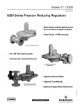
Figure 1. Typical Type S204 Gas Regulator
Installation
Scope of the Manual
!
Description
Types S204 and S206 gas service regulators are
typically installed on industrial and commercial
applications. Both regulators have a low outlet
pressure shutoff mechanism that shuts gas flow off
if the required minimum outlet pressure cannot be
maintained. Type S206 also has an internal relief valve
that gives partial downstream overpressure protection.
Specifications
The Specifications table lists the specifications for
Types S204 and S206 constructions. The following
information is stamped on the regulator at the factory:
type number, date of manufacture, spring range, port
size, maximum inlet pressure, maximum operating
outlet pressure, and outlet pressure which may
damage regulator parts.
Personal injury or system damage
may result if this regulator is installed,
without appropriate overpressure
protection, where service conditions
could exceed the limits given on
the regulator nameplate. Regulator
installations should be adequately
protected from physical damage.
All vents should be kept open to permit
free flow of gas to the atmosphere.
Protect openings against entrance of
rain, snow, insects, or any other foreign
material that may plug the vent or vent
line. On outdoor installations, point the
spring case vent downward to allow
condensate to drain (see Figure 2). This
minimizes the possibility of freezing
and of water or other foreign materials
entering the vent and interfering with
proper operation.
www.fisherregulators.com
D400011X012
This instruction manual provides instructions and a parts
list for Types S204 and S206 gas service regulators.
WARNING
Types S204 and S206
Specifications
Body Size and End Connection Style
1-1/2 or 2 NPT inlet and outlet
NPS 2 (DN 50) CL125 FF
Outlet Pressure Ranges
3.5-inches w.c. to 3.25 psig
(9 mbar to 0,22 bar)
Maximum Allowable Inlet Pressure(1)
See Table 1
Temperature Capabilities(1)
-20° to 150°F (-29° to 66°C)
Maximum Emergency Outlet Pressure(1)
15 psig (1,0 bar)
Pressure Registration
Internal
Seat Ring Diameters
3/8, 1/2, 5/8, 1, and 1-3/16-inches
(9,5; 13; 16; 25; and 30 mm)
Approximate Weight
22 pounds (10 kg)
1. The pressure/temperature limits in this Instruction Manual or any applicable standard limitation should not be exceeded.
!
WARNING
Under enclosed conditions or indoors,
escaping gas may accumulate and be
an explosion hazard. In these cases,
the vent should be piped away from the
regulator to the outdoors.
CAUTION
Like most regulators, Types S204 and S206
regulators have an outlet pressure rating
lower than their inlet pressure rating. If
actual inlet pressure can exceed the
outlet pressure rating, outlet overpressure
protection is necessary. However,
overpressuring any portion of the
regulators beyond the limits in Table 1 may
cause leakage, damage to the regulator
parts, or personal injury due to bursting of
pressure-containing parts.
Some type of external overpressure
protection should be provided if inlet
pressure will be high enough to damage
downstream equipment. Common
methods of external overpressure
protection include relief valves,
monitoring regulators, shutoff devices,
and series regulators.
If the regulator is exposed to an
overpressure condition, it should be
inspected for any damage that may
2
have occurred. Regulator operation
below these limits does not preclude
the possibility of damage from external
sources or from debris in the pipeline.
Before installing the regulator, check for damage
which might have occurred in shipment. Also, check
for dirt or foreign matter which may have accumulated
in the regulator body or in the pipeline. Apply pipe
compound to the external threads of the pipeline and
install the regulator so that flow is in the direction of
the arrow cast on the body. The diaphragm casing
assembly can be rotated to any position relative to the
body. Loosen the two cap screws (key 18, Figure 5) in
order to rotate the diaphragm casing assembly.
Do not install the regulator in a location where there
can be excessive water accumulation, such as directly
beneath a downspout.
If the regulator is used in conjunction with a Type 289H
relief valve, it should be installed as shown in Figure 2.
The outside end of the vent line should be protected
with a rainproof assembly.
The Type 289H should be set 10-inches w.c. (25 mbar)
higher than the outlet pressure setting of the regulator,
up to 30-inches w.c. (75 mbar) reduced pressure.
For pressure greater than this, set the Type 289H
21-inches w.c. (52 mbar) higher than the outlet
pressure setting of the regulator.
The Types S204 and S206 regulators have 1 NPT
screened vent openings in the spring case. If necessary
to vent escaping gas away from the regulator, install
a remote vent line in the spring case tapping. Vent
piping should be as short and direct as possible with a
Types S204 and S206
Table 1. Inlet Pressure
PROTECT VENT PIPE
WITH RAIN CAP
INLET PRESSURE SETTING, PSIG (bar)
SEAT RING SIZE,
INCHES (mm)
Optimum
Maximum
3/8 (9,5)
100 (6,9)
100 (6,9)
1/2 (13)
75 (5,2)
100 (6,9)
5/8 (16)
60 (4,1)
75 (5,2)
1 (25)
20 (1,4)
30 (2,1)
1-3/16 (30)
7 (0,48)
15 (1,0)
TYPE S204 REGULATOR
NPS 2 (DN 50)
TYPE 289H
RELIEF VALVE
Table 2. Maximum Outlet Pressure Setting
DIAPHRAGM PLATES
MAXIMUM OUTLET(1)
Light
30-inches w.c. (75 mbar)
Heavy
3.25 psig (0,22 bar)
1. Maximum emergency outlet (casing) pressure for S200 Series is 15 psig (1,0 bar).
Figure 2. Type S204 Regulator Installed with the Vent
Pointed Downward and with a Type 289H Relief Valve for
High Capacity Relief
Table 3. Spring Chart
SPRING RANGE,
INCHES W.C. (mbar)
3.5 to 5
5 to 7
6.5 to 9.5
8.5 to 18
14 to 30
(9 to 12)
(12 to 17)
(16 to 24)
(21 to 45)
(35 to 75)
1 to 2 psig (69 mbar to 0,14 bar)
1.5 to 3.25 psig (0,10 to 0,22 bar)
AJ4698
A1721
PART
NUMBER
COLOR
CODE
1D892527022
1D892627022
1D892727012
1D893227032
1D893327032
Brown
Red
Black
Gray
Dark Green
1H975827032
1H975927032
Dark Blue
Orange
minimum number of bends and elbows. The remote
vent line should have the largest practical diameter.
Vent piping on regulators with internal relief (Type S206)
must be large enough to vent all relief valve discharge
to atmosphere without excessive backpressure and
resulting excessive pressure in the regulator.
Periodically check all vent openings to be sure that
they are not plugged.
Maximum outlet pressure settings are shown in
Table 2. Outlet pressure more than 2 psi (0,14 bar)
(light diaphragm plate) or 3 psi (0,21 bar) (heavy
diaphragm plate) above the setpoint may damage
internal parts such as the diaphragm plate and valve
disk. The maximum emergency (casing) outlet
pressure is 15 psig (1,0 bar).
Startup
Figure 3. Reset Lever
startup. Procedures used in putting this
regulator into operation must be planned
accordingly if the downstream system is
pressurized by another regulator or by a
manual bypass.
If the downstream system is not pressurized by
another regulator or manual bypass valve, use the
following procedure to start up the regulator.
1. Slowly open the upstream shutoff valve.
CAUTION
Pressure gauges should always be used
to monitor downstream pressure during
2. The low pressure shutoff mechanism has to be reset.
To do this, remove the closing cap (key 4, Figure 5)
and pull quickly upward on the reset stem (key 24).
3
Types S204 and S206
PUSHER POST
EXTENSION
BACK DISK
DIAPHRAGM
ASSEMBLY
MAIN VALVE
DISK
PUSHER POST
ASSEMBLY
A6197
INLET PRESSURE
SEAT RING
OUTLET PRESSURE
INLET
INLETPRESSURE
PRESSURE
ATMOSPHERIC PRESSURE
OUTLET
OUTLETPRESSURE
PRESSURE
ATMOSPHERIC
PRESSURE
ATMOSPHERIC
PRESSURE
Figure 4. Operational Schematic
Note
Follow the same procedure if the
regulator shuts off during service. A
lever (Part No. ORO6172509A, Figure 3) is
needed to reset the regulators when the
outlet pressure setting is 7-inches w.c.
(17 mbar) or more.
Shutdown
Installation arrangements may vary, but in any
installation it is important that the valves be opened or
closed slowly and that the outlet pressure be vented
before venting inlet pressure to prevent damage caused
by reverse pressurization of the regulator. The steps
below apply to the typical installation as indicated.
3. Slowly open the downstream shutoff valve.
1. Slowly close the upstream shutoff valve.
4. Check all connections for leaks.
2. The back disk assembly in the regulator will
shut off as inlet pressure drops. Upstream and
downstream pressure can then be bled off.
Adjustment
The range of allowable pressure settings is stamped
on the nameplate. If the required setting is not
within this range, substitute the correct spring (as
shown in Table 3). If the spring is changed, be
sure to change the nameplate to indicate the new
pressure range. A pressure gauge should always
be used to monitor downstream pressure while
adjustments are being made.
1. Remove the closing cap (key 4, Figure 5 or 6).
2. To increase the outlet setting, turn the adjusting
screw (key 3) clockwise. To decrease the outlet
setting, turn the adjusting screw counterclockwise.
3. Replace the closing cap.
4
Principle of Operation
Refer to Figure 4. When downstream demand
decreases, the pressure under the diaphragm
increases. This pressure overcomes the regulator
setting (which is set by a spring). Through the action
of the pusher post assembly, the valve disk moves
closer to the seat ring and reduces gas flow. If
demand downstream increases, pressure under the
diaphragm decreases. Spring force pushes the pusher
post assembly downward, the valve disk moves away
from the seat ring, and the gas flow increases.
As downstream pressure drops under high demand,
the diaphragm will drop to its lowest position and
the main disk will move to its farthest position from
Types S204 and S206
the seat ring. This allows the spring in the back disk
assembly to seat the back disk against the seat ring
and shut off flow. This condition is maintained until the
regulator is manually reset by quickly pulling upward
on the pusher post extension in the spring case.
The back disk assembly will also close if inlet pressure
drops too low, even if demand is not high.
Maintenance
!
WARNING
To avoid personal injury or equipment
damage, do not attempt any
maintenance or disassembly without
first isolating the regulator from system
pressure and relieving all internal
pressure as described in “Shutdown”.
Regulators that have been disassembled
for repair must be tested for proper
operation before being returned to
service. Only parts manufactured
by Emerson Process Management
Regulator Technologies, Inc., should be
used for repairing Fisher® regulators.
Relight pilot lights according to normal
startup procedures.
Due to normal wear or damage that
may occur from external sources, this
regulator should be inspected and
maintained periodically. The frequency
of inspection and replacement of parts
depends upon the severity of service
conditions or the requirements of local,
state, and federal rules and regulations.
Disassembly to Replace Diaphragm
Refer to Figure 5 or 6.
1. Remove the closing cap (key 4), and turn the
adjusting screw (key 3) counterclockwise to
ease spring compression.
2. Remove the adjusting screw and the spring (key 2).
3. Remove hex nuts (key 15) and cap screws (key 14).
Separate the upper spring case (key 1) from the
lower casing assembly (key 9).
4. Slide the diaphragm and diaphragm plate assembly
(key 7) away from the body (key 21) to unhook the
pusher post (key 8) from the lever (key 10). Lift off
the diaphragm and diaphragm plate assembly.
5. Unscrew the reset stem (key 24) from the
pusher post.
6. The diaphragm head can now be lifted off the
diaphragm plate assembly.
7. Reassemble the spring case unit in the reverse
order of the above steps.
Note
Before tightening the cap screw or
stem into the pusher post, place the
loosely-assembled diaphragm assembly
into position in the lower casing, being
sure that the pusher post is hooked on
the lever. Rotate the diaphragm so that
the diaphragm and lower casing holes
are aligned. Tighten cap screw or stem.
Tighten the spring case cap screws
finger-tight only. After replacing the
spring and adjusting screw, turn the
adjusting screw in about half way. This
procedure will ensure proper slack in
the diaphragm. Finish tightening the
cap screws.
Note
Take care not to pinch or tear the
diaphragm when reassembling.
Disassembly to Replace Valve Disks and
Seat Ring
Refer to Figure 5 or 6.
1. Remove the bolts (key 18) which hold the lower
spring casing (key 9) to the body (key 21).
Separate the lower spring casing from the body.
2. Check the body O-ring (key 19) for wear.
3. Examine the valve disk (key 16) for nicks, cuts,
and other damage. Unscrew the disk holder
assembly from the valve stem assembly (key 13)
and replace it with a new part if necessary.
4. If the seating edge of the seat ring (key 20)
is nicked or rough, remove the seat ring from
5
Types S204 and S206
SECTION A-A
A
62
58
VENT
A
60
57
18
4
55
56
59
7
24
5
61
13
3
21
2
16
6
28
32
14
27
1
26
15
34
8
19
10
11
9
20
30
33
12
Figure 5. Type S204 Regulator Assembly
4
5
25
32
7
24
13
3
21
2
16
6
28
14
27
1
26
15
34
8
19
10
11
9
Figure 6. Type S206 Regulator Assembly
6
20
30
33
12
Types S204 and S206
the body. Change to a new part when
reassembling the regulator. (If the seat ring is
being replaced with a different sized part, change
the nameplate to state the new size and maximum
inlet pressure.)
5. Reassemble the regulator in reverse order of the
above steps.
6. To inspect the back body disk (key 27), unscrew
the body cap (key 20), and the disk assembly
can be taken out.
Parts Ordering
The type number, seat ring (port) size, and date of
manufacture are stamped on the nameplate. Always
provide this information in any correspondence with
your local Sales Office regarding replacement parts
or technical assistance. If construction changes are
made in the field, be sure that the nameplates are
also changed to reflect the most recent construction.
Parts List
Key Description 1
Spring Case
Aluminum
Pinned for heavy spring
2
Spring, Steel
3
Adjusting Screw, Aluminum
4
Closing Cap, Aluminum
5* Closing Cap Gasket, Neoprene (CR)
6
Lower Spring Seat, Aluminum
7
Diaphragm and Head Assembly
Use with 1D893327032 and lighter springs
Use with 1H975827032 and heavier springs
7A* Diaphragm, Nitrile (NBR)
Use with 1D893327032 and lighter springs
Use with 1H975827032 and heavier springs
7B Diaphragm Head, Steel
Use with 1D893327032 and lighter springs
Use with 1H975827032 and heavier springs
8
Pusher Post, Aluminum
Type S204 only
9
Lower Casing Assembly,
Aluminum
10
Lever, Steel
Part Number
4L142308032
1J718699022
See Table 3
1L928608012
1L928308012
1N446206992
1L928708012
1L1544X0012
1L1545X0012
1K978102072
1L154302052
1H977928992
1H978025032
2H980608012
1H9751X0012
1H974028992
Key Description 11 Pin, 303 SST
12 Machine Screw, Steel (2 required)
13 Valve Stem Assembly
14 Cap Screw, Steel (12 required)
15 Hex Nut, Steel,
Cadmium plate (12 required)
16* Disk Holder Assembly
For Natural Gas Service
For Manufactured Gas
(5/8-inch (16 mm) and larger Seat Rings)
18 Cap Screw, Steel,
Cadmium plate (2 required)
19* O-Ring, Nitrile (NBR)
20 Seat Ring, Aluminum
3/8-inch (9,5 mm) Port Diameter
1/2-inch (13 mm) Port Diameter
5/8-inch (16 mm) Port Diameter
1-inch (25 mm) Port Diameter
1-3/16-inch (30 mm) Port Diameter
21 Body
Cast Iron
1-1/2 NPT
2 NPT
NPS 2 (DN 50) CL125 FF
125 pounds (57 kg)
Steel
1-1/2 NPT
2 NPT
24 Reset Stem, Steel
Type S204
Type S206
25 Relief Valve Spring, Steel, Cadmium, Plate
(Type S206 only)
26 Back Disk Spring
302 SST
27* Back Disk Holder Assembly
28 Disk Spacer, Aluminum
For Natural Gas Service
For Manufactured Gas
(5/8-inch (16 mm) and larger Seat Rings)
30 Back Body Cap, Aluminum
32 Nameplate, Aluminum
33 Valve Stem, Aluminum
34 Gasket, Asbestos
55 Flapper Stem, 302 SST
56 Lower Flapper, Nylon (PA)
57 Upper Flapper, Nylon (PA)
58 Seat Ring, 302 SST
59 Self-Tapping Screw, Steel (3 required)
60 Spring, 302 SST (2 required)
61 Screen, Monel®
62 Snap Ring, 302 SST
Part Number
1H972935032
1B420428982
1H9748000A2
1B136324052
1A309324122
1P7349000A2
1J1680X0012
1H974724052
T12587T0012
1U588409022
1J718509022
1H980509022
1H980709022
1H980809022
1J190519012
1H974319012
2K184319012
1K788022012
1K792222012
1H980424272
1H969224272
1H976027012
1A866837022
1H9739000A2
1H973609012
1J168309012
1R236109022
11A5497X032
1H973509082
1F826804022
1H976335022
1H976406992
1H976506992
T13609T0012
1H976728982
1H976837022
1E564843122
1E564937022
*Recommended Spare Parts
Monel® is a mark owned by Special Metals Corporation.
7
Types S204 and S206
Industrial Regulators
Natural Gas Technologies
TESCOM
Emerson Process Management
Regulator Technologies, Inc.
Emerson Process Management
Regulator Technologies, Inc.
Emerson Process Management
Tescom Corporation
USA - Headquarters
McKinney, Texas 75069-1872 USA
Tel: 1-800-558-5853
Outside U.S. 1-972-548-3574
USA - Headquarters
McKinney, Texas 75069-1872 USA
Tel: 1-800-558-5853
Outside U.S. 1-972-548-3574
USA - Headquarters
Elk River, Minnesota 55330-2445 USA
Tel: 1-763-241-3238
Asia-Pacific
Shanghai, China 201206
Tel: +86 21 2892 9000
Asia-Pacific
Singapore, Singapore 128461
Tel: +65 6777 8211
Europe
Bologna, Italy 40013
Tel: +39 051 4190611
Europe
Bologna, Italy 40013
Tel: +39 051 4190611
Gallardon, France 28320
Tel: +33 (0)2 37 33 47 00
Middle East and Africa
Dubai, United Arab Emirates
Tel: +971 4811 8100
Europe
Selmsdorf, Germany 23923
Tel: +49 (0) 38823 31 0
For further information visit www.fisherregulators.com
The Emerson logo is a trademark and service mark of Emerson Electric Co. All other marks are the property of their prospective owners. Fisher is a mark owned by Fisher Controls, Inc., a
business of Emerson Process Management.
The contents of this publication are presented for informational purposes only, and while every effort has been made to ensure their accuracy, they are not to be construed as warranties or
guarantees, express or implied, regarding the products or services described herein or their use or applicability. We reserve the right to modify or improve the designs or specifications of such
products at any time without notice.
Emerson Process Management does not assume responsibility for the selection, use or maintenance of any product. Responsibility for proper selection, use and maintenance of any Emerson
Process Management product remains solely with the purchaser.
©Emerson Process Management Regulator Technologies, Inc., 1978, 2010; All Rights Reserved