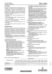
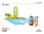
1
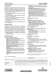
S203 Series
Instruction Manual
Form 2216
December 2008
S203 Series Relief Monitor Regulators
W2109
Figure 1. Type S203 Relief Monitor Regulator
!
Warning
Fisher® regulators must be installed,
operated, and maintained in accordance
with federal, state, and local codes, rules
and regulations, and Fisher instructions.
If the regulator vents gas or a leak
develops in the system, service to the unit
may be required. Failure to correct trouble
could result in a hazardous condition.
Call a gas service person to service
the unit. Only a qualified person must
install or service the regulator.
Introduction
Scope of Manual
The S203 Series allows single-unit overpressure
protection. The regulators also minimize the venting of
large volumes of gas to the atmosphere.
Type S203—Spring-loaded regulator with open
throat construction that gives internal registration of
downstream pressure. Outlet pressure is from 2 to
30-inches w.c. (5 to 75 mbar) in five ranges.
Type S203H—Same as Type S203 but with outlet
pressure from 1 to 3.25 psig (0,07 to 0,22 bar) in
two ranges.
Type S203P-1—Spring loaded regulator with blocked
throat and blocked pitot tube construction for use with
a downstream control line.
Type S203P-2—Same as Type S203P-1 but with stem
seal O-ring for positive seal.
Type S203P-3—Same as Type S203P-1 but with stem
seal O-ring and wiper ring for dirty gas applications.
D400010X012
This instruction manual provides instructions and a
parts list for the S203 Series relief monitor regulators.
Description
www.emersonprocess.com/regulators
S203 Series
Specifications
Body Sizes and End Connection Style
1-1/2, 1-1/2 x 2, or 2-inch body with
NPT connections
Maximum Allowable Inlet Pressure (Body Rating)(1)
See Table 3
Maximum Allowable Casing Pressure(1)
15 psig (1,0 bar) casing pressure
Maximum Operating Outlet Pressure to Avoid
Internal Part Damage
Light Diaphragm Plate: 2 psi (0,14 bar) above
outlet pressure setting
Heavy Diaphragm Plate: 3 psi (0,21 bar) above
outlet pressure setting
Point Where Relief/Monitor Functions
Approximately 7-inches w.c. to 1 psig
(17 mbar to 0,07 bar) over outlet setting
Outlet Pressure Ranges
2-inches w.c. to 3.25 psig (5 mbar to 0,22 bar)
Seat Ring Port Diameters
1/4, 3/8, 1/2, 3/4, 1, and 1-3/16-inches
(6,4; 9,5; 13; 19; 25; and 30 mm)
Temperature Capabilities(1)
–20° to 170°F (–29° to 77°C)
Pressure Registration
Types S203 and S203H: internal
Type S203P: downstream control line
Approximate Weight
27 pounds (12 kg)
1. The pressure/temperature limits in this instruction manual or any applicable standard limitation should not be exceeded.
Specifications
The Specifications section list the specifications for the
S203 Series. The following information is stamped
on the regulator at the factory: type number, date of
manufacture, outlet pressure range, port (seat ring) size,
monitor spring part number, and monitor spring range.
Principle of Operation
The following describes operation through internal
registration as shown in Figure 3. A unit with a
downstream control line operates the same except
that the throat and pitot tube are blocked, and a
downstream control line is tapped into the lower casing
and the monitor spring case.
Downstream pressure registers under the main
regulator diaphragm through the turbo-booster tube
in the throat and on the monitor diaphragm assembly
through the pitot tube. Inlet pressure registers on both
sides of the monitor piston through a registration hole in
the center resulting in balanced operation. Thus, under
normal conditions, as downstream pressure fluctuates
due to load changes the main regulator disk and monitor
piston both move toward or away from the seat ring.
If the downstream pressure reaches overpressure
conditions (7-inches w.c. to 1 psig (17 mbar to 0,07 bar))
above the outlet pressure setting — depending on the
main regulator spring), the internal relief valve opens.
At the same time, downstream pressure on the monitor
diaphragm moves the monitor piston closer to the seat
ring restricting the port. This minimizes or prevents
2
further flow through the port, enabling the relief valve to
relieve the downstream overpressure conditions.
The combination of the restriction in the relief valve
(key 94, Figure 4) and the positioning of the monitor
piston near the inlet side of the seat ring limits the
maximum downstream pressure and the related flow
through the relief valve to the values indicated in Table 1.
As downstream pressure drops back to normal, the relief
valve closes and the monitor piston moves away from
the seat ring automatically restoring normal operation.
Installation
!
Warning
Personal injury or system damage
may result if this regulator is installed,
without appropriate overpressure
protection, where service conditions
could exceed the limits given in the
Specifications section. Regulator
installations should be adequately
protected from physical damage.
All vents should be kept open to permit
free flow of gas to the atmosphere.
Protect openings against entrance of
rain, snow, insects, or any other foreign
material that may plug the vent or vent
line. On outdoor installations, point
the spring case and monitor casing
vent downward to allow condensate to
S203 Series
Table 1. Maximum Downstream Pressure Build-up and Relief Valve Flow
relief monitor
spring part
number
(color code)
type number
Up to 5 (Up to 12)
0.8 (0,05)
0
950 (26)
1.0 (0,07)
1
1000 (27)
8 to 14 (20 to 35)
1.25 (0,09)
2
1200 (32)
8 to 12 (20 to 30)
1.4 (0,10)
0
1350 (36)
10 to 20 (25 to 50)
1.8 (0,12)
1
1600 (43)
14 to 28 (35 to 70)
2.8 (0,19)
2
1900 (51)
11 to 21 (27 to 52)
2.2 (0,15)
0
1800 (48)
18 to 33 (45 to 82)
3.0 (0,21)
1
2000 (54)
28 to 45 (70 to 112)
3.8 (0,26)
2
2200 (59)
0.5 to 1.0 psig (0,03 to 0,07 bar)
3.0 (0,21)
0
2200 (59)
0.75 to 1.6 psig (0,05 to 0,11 bar)
4.0 (0,28)
1
2500 (67)
1.25 to 2.25 psig (0,09 to 0,16 bar)
5.0 (0,35)
2
3000 (80)
1.25 to 3.25 psig (0,09 to 0,22 bar)
6.0 (0,41)
3
3000 (80)
1L255827132
(Red)
1L255927132
(Blue)
1V224227012
S203H/
S203P
1V224227012
(Silver)
Table 2. Main Spring Pressure Ranges
Spring Part
Number
Color
Code
2 to 4.5
3.5 to 6.5
5 to 9
8.5 to 18
14 to 30
1D892527022
1D892627022
1D892727012
1D893227032
1D893327032
Brown
Red
Silver
Grey
Dark Green
1H975827032
1H975927032
Dark Blue
Orange
(5 to 11)
(9 to 16)
(12 to 22)
(21 to 45)
(35 to 75)
1 to 2 psig (0,07 to 0,14 bar)
1.5 to 3.25 psig (0,10 to 0,22 bar)
C
vent
S203H/
S203P
Spring Range,
Inches w.c. (mbar)
vent
S203,
S203P
d
vent
Type
Number
Table 3. Inlet Pressures
Seat Ring
Diameter,
inches (mm)
1/4 (6,35)
3/8 (9,53)
1/2 (12,7)
3/4 (19,1)
1 (25,4)
1-3/16 (30,2)
E
Maximum Inlet Pressure, Psig (bar)
Types S203, S203P
Type S203H
125 (8,6)
125 (8,6)
100 (6,9)
125 (8,6)
125 (8,6)
100 (6,9)
60 (4,1)
25 (1,7)
13 (0,90)
60 (4,1)
30 (2,1)
14 (0,97)
Table 4. Maximum Outlet Pressure Setting(1)
Type Number
Maximum flow
through relief
valve, SCFH (Nm3/h) of
0.6 Specific Gravity
natural gas
number
of lower
spring seats
required
4 to 9.5 (10 to 24)
1L255727132
(Green)
S203, S203P
maximum
downstream
pressure build-up,
psig (bar)
Outlet pressure range,
Inches w.c. (mbar)
Maximum Outlet Pressure
S203 or S203P
30-inches w.c. (75 mbar)
S203H/S203P
3.25 psig (0,22 bar)
1. Maximum emergency outlet (casing) pressure for S203 Series is 15 psig (1,03 bar).
drain (see Figure 2). This minimizes the
possibility of freezing and of water or
other foreign materials entering the vent
and interfering with proper operation.
Under enclosed conditions or indoors,
escaping gas may accumulate and be
an explosion hazard. In these cases,
the vents should be piped away from the
regulator to the outdoors.
A4196
vent
F
POiNT VENT DOWN
Figure 2. Various Vent Positions
caution
Like most regulators, S203 Series
regulators have an outlet pressure rating
lower than their inlet pressure rating.
Overpressuring any portion of the
regulators beyond the limits in Tables 3
and 4 may cause leakage, damage to
regulator parts, or personal injury due to
bursting of pressure-containing parts.
If the regulator is exposed to an
overpressure condition, it should be
inspected for any damage that may
have occurred. Regulator operation
below these limits does not preclude
the possibility of damage from external
sources or from debris in the pipeline.
3
S203 Series
Before installing the regulator, check for damage which
might have occurred in shipment. Also check for dirt
or foreign matter which may have accumulated in the
regulator body or in the pipeline. Apply pipe compound
to the male threads of the pipeline and install the
regulator so that flow is in the direction of the arrow cast
on the body. The diaphragm casing assembly can be
rotated to any position relative to the body. Loosen the
two cap screws holding the union ring (key 18, Figure 4)
in order to rotate the diaphragm casing assembly.
Do not install the regulator in a location where there
can be excessive water accumulation, such as directly
beneath a downspout.
The regulator vent is 1-inch FNPT and the monitor vent
is 1/4-inch FNPT. The vent openings are screened to
prevent insects from entering. On outdoor installations,
the vent opening must be pointing down, see Figure 2, for
protection against the elements and to allow condensate
to drain.
Indoor installations require a separate vent line be run
from each vent to a safe outdoor location. The vent
lines should be of as large diameter pipe as practical
with a minimum number of bends. Remove the vent
screen when attaching the piping to the vent. A weather
resistant vent assembly, such as Fisher® Type Y602,
should be installed at the end of each vent piping
with the vent assembly opening pointing down. The
vent assembly should be in a protected location as
explained above for regulators installed outdoors.
A program of regular inspection of the vent opening
should be established to see that it has not become
plugged by foreign material. On some installations,
such as in areas of heavy snowfall, it may be
necessary to install the regulator beneath a protective
hood. If other protection is provided from the elements,
the vent should be pointing or sloping down sufficiently
to allow any condensate to drain.
It is advisable that the downstream piping be the same
size as the regulator outlet for a minimum distance of
18-inches (457 mm) or to the meter inlet. Replace the
regulator if water gets into the spring case or the lower
casing to the regulator.
Downstream Control Line
The Types S203P-1, -2, and -3 units must be installed
with an external downstream control line. Install the
control line before putting the regulator into operation or
the regulator will remain wide-open. The downstream
control line should be pipe of at least 1/2-inch
(13 mm) diameter and connected to a straight section
of outlet piping 5 to 10 pipe diameters downstream of
the regulator. A hand valve should be installed in this
4
section of the control line. This hand valve can be
throttled down to dampen out pulsations which may
cause instability or cycling of the regulator. However, the
control line hand valve must never be closed completely
during operation. Since the throat is blocked to isolate
the main diaphragm and a sealing screw (key 99,
Figure 5) in the pitot tube isolates the monitor
diaphragm, install a tee in the control line between the
regulator and the hand valve. Then run one line from
the tee to the connection in the lower casing assembly
which is tapped in the S203P Series and another line
from the tee to the tapped connection (key 46, Figure 4)
in the monitor spring case.
Startup
caution
Pressure gauges should always be used
to monitor downstream or control line
pressures during startup. Downstream
or control line pressure must never
exceed the setpoint (dictated by the
spring setting) by more than 2 psi
(0,14 bar) (light diaphragm plate) or 3 psi
(0,21 bar) (heavy plate). If it does, the
valve seat and/or diaphragm plate may
be damaged. Procedures used in putting
the regulator into operation must be
planned accordingly if the downstream
system is pressurized by another
regulator or by a manual bypass.
If the downstream system is not pressurized by
another regulator or manual bypass valve, use the
following procedure:
1. Open the hand valve in the control line
(Type S203P-1, -2, or -3).
2. Slowly open the upstream shutoff valve.
3. Slowly open the downstream shutoff valve.
4. If the regulator (with a downstream control line) has
a tendency to pulsate, throttle down the hand valve in the control line, but never close it completely while the regulator is in operation.
5. Check all connections for leaks.
6. Light the appliance pilots.
Adjustment
To increase the outlet pressure setting of the regulator,
compress the main spring (key 2, Figure 4) by removing
the closing cap (key 4, Figure 4) and turning the adjusting
Type S203
July 2007
Type S203
S203 Series
50A9737-F
A4195
A6564
INLET
PRESSURE
INLET
PRESSURE
OUTLET
PRESSURE
OUTLET
PRESSURE
PRESSURE
ATMOSPHERIC
PRESSURE
INLET ATMOSPHERIC
PRESSURE
OUTLET PRESSURE
ATMOSPHERIC PRESSURE
Figure 3. Type S203 Operational Schematic
screw (key 3) clockwise into the spring case. To decrease
the outlet pressure setting, turn the adjusting screw
counterclockwise out of the spring case. Replace the
closing cap after making this adjustment. If desired, the
closing cap may be wired to the hole provided in the
spring case (key 1) to discourage tampering.
Compare the outlet pressure ranges between Tables 1
and 2. If the main spring (key 2) is adjusted outside of
the range of the monitor spring (key 84), lower spring
seats (key 85) may have to be added or removed. If
the monitor range is below the outlet pressure setting,
the monitor may try to take over as the outlet pressure
regulator. If the monitor range is above the outlet
pressure setting, the monitor will be too sluggish to
properly operate as a monitor.
Shutdown
Installation arrangements may vary, but in any
installation it is important that the valves be opened
or closed slowly and that the outlet pressure be
vented before venting inlet pressure to prevent
damage caused by reverse pressurization of the
regulator. The steps below apply to the typical
installation as indicated.
1. Open valves downstream of the regulator.
2. Slowly close the upstream shutoff valve.
3. Inlet pressure will automatically be released downstream as the regulator opens in response to the lowered pressure on the diaphragm.
Maintenance
!
Warning
Before disassembling the regulator,
isolate it from the system pressure
and release pressure from the body
outlet. Inlet pressure will automatically
be released as the regulator opens in
response to the lowered pressure on
the diaphragm.
Regulators that have been disassembled
for repair must be tested for proper
operation before being returned to
service. Only parts manufactured by
Fisher® should be used for repairing
Fisher regulators. Relight pilot lights
according to normal startup procedures.
To Replace Main Diaphragm
1. Referring to Figure 4 remove the closing cap
(key 4) and turn the adjusting screw (key 3) out of the spring case (key 1). Inspect the closing cap gasket (key 5).
2. Take the spring (key 2) out of the regulator.
3. Remove cap screw (key 14) holding the spring case to the lower casing (key 9). Remove the
spring case.
5
S203 Series
4. The diaphragm and plate assembly (key 7) can be removed by sliding the pusher post (key 8) off the lever (key 10).
5. Unscrew the stem (key 24) from the diaphragm assembly, which allows the assembly to be separated into the following parts: stem (key 24),
relief valve spring (key 25), relief restriction
(key 94), lower spring seat (key 6), diaphragm and plate assembly (key 7), and pusher post (key 8).
6. If necessary, install a new diaphragm
(key 7A). The original diaphragm will be
glued to the diaphragm plate. Pull them apart and scrape the surface of the plate clean. Coat the plate with a good grade of gasket sealer and place the patterned side of the new diaphragm next to the diaphragm plate. Continue reassembly
in the reverse order of the above procedures.
7. Before tightening the stem into the pusher post to secure the diaphragm and plate assembly, place the loosely assembled parts into the lower casing being sure the pusher post is properly hooked on the lever. Rotate the diaphragm so that the diaphragm and lower casing holes are aligned. Then tighten the stem and proceed with reassembly. Apply an anti-seize compound to the threads of the adjusting screw and closing cap.
caution
There must be slack in the main
diaphragm in order for the unit to
operate properly. Before tightening the
cap screws (key 14), replace the main
spring and adjusting screw. Tighten
the adjusting screw slightly. This will
stretch the oversized diaphragm to
ensure a smooth seal and create the
necessary slack for good regulation.
8. Upon reassembly test the unit and all connections for leaks.
To Replace Valve Disk and Seat Ring
Refer to either Figure 4 or 5 unless specified.
1. Unscrew the two bolts (key 18, Figure 4) which pass through the body flange into the union ring.
2. Remove the actuator portion of the regulator
from the body (key 21, Figure 4). Inspect the
body O-ring (key 19) and replace on reassembly
if necessary.
6
3. Unscrew the disk holder assembly (key 16) from the valve stem assembly (key 13, Figure 4). Examine the disk for nicks, cuts, and other damage, and replace it on reassembly if necessary.
Note
If maintenance is being performed on
an S203P Series regulator, the parts
which block the throat can be removed
and inspected while the disk holder
assembly is off. Remove the retaining
ring (key 63, Figure 5) and slide the stem
adaptor (key 67, Figure 5) off the valve
stem assembly. Inspect the O-rings and
wiper ring (keys 64, 65, and 66, Figure 5)
and replace worn or damaged parts.
4. Check the seating edges of the seat ring (key 20) for nicks or roughness which would prevent proper
shutoff. (It may be necessary to remove the seat ring to check the seating edge on the monitor
side.) If the seat ring is removed or a new one is
installed, treat the male threads with a pipe
compound before reassembling.
5. If no further maintenance is required, the body can be reassembled in the reverse order of the above procedure.
Monitor Maintenance
Refer to Figure 5 unless directed otherwise.
1. Remove the four cap screws (key 80, Figure 4) and remove the monitor from the regulator body. Inspect the O-rings (keys 90 and 82).
2. Unscrew the eight cap screws (key 81, Figure 4), lift off the monitor spring case (key 76, Figure 4), and remove the diaphragm (key 78).
3. Hold the disk holder assembly (key 27) and turn the diaphragm plate (key 83) off the stem of the piston assembly (key 86). The monitor spring
(key 84) and the spring seats (key 85) can now be changed. This also frees the piston and guide assembly for inspection.
Refer to Figure 6 for key numbers identified in steps 4 through 8.3 unless otherwise specified.
caution
When the piston assembly (key 86) is
pushed through the piston guide (key 89),
S203 Series
the piston ring halves (key 97) may eject
from the groove due to the ring expander
(key 96). Be prepared to catch these
brittle graphite rings to prevent them
from being chipped or damaged.
8.3 Coat the O-ring (key 88) with elastomer lubricant then carefully work the stem seal
O-ring over the stem threads and replace the retainer (key 87). A damaged O-ring may result in a gas leak out the vent (key 93, Figure 5).
4. Push the piston assembly through the guide and inspect the piston ring halves.
8.4 Replace the necessary number of lower spring seats (see Table 1), the spring, and turn the diaphragm plate onto the stem until it hits bottom. Do not tighten the plate on the stem as this is unnecessary and may make disassembly difficult.
5. If it is necessary to replace the disk holder assembly (key 27), remove the disk holder screw (key 92) and washer (key 98).
Note
When replacing the disk holder
assembly, tighten the screw while
holding the piston. Do not tighten the
screw after the piston assembly has
been replaced in the guide and the
diaphragm plate has been turned on to
the stem. If the screw is tightened while
holding onto the diaphragm plate, the
stem may be tightened too much into
the diaphragm plate causing subsequent
disassembly to be difficult.
6. Remove the O-ring retainer (key 87) and inspect the stem seal O-ring (key 88).
7. Clean the inside surface of the piston guide to be sure it is free of grease and foreign particles. The surface of the piston should also be clean to ensure smooth operation.
8. Reassemble the monitor in the following manner:
8.1 Fasten the disk holder assembly to the piston assembly, if not done previously, and slide the piston into the piston guide. Make sure it moves smoothly with no grit or dirt to
hinder operation.
8.2 Push the piston assembly out of the guide far enough to expose the ring groove. If a new piston ring is to be installed, it will arrive in one piece. Break it in half by striking it over the sharp edge of a table. Install the ring expander (key 96) then install the piston ring halves making
sure the matching ends are mated together.
Squeeze the two halves of the piston ring together
and push the piston into the guide.
8.5 Align the diaphragm on the roll pin (key 79,
Figure 5) with the patterned side next to the
diaphragm plate.
8.6 Align the spring case on the roll pin and install the eight cap screws. Tighten them down evenly to 5 to 7 foot-pounds torque, allowing as much slack as possible in the diaphragm.
8.7 Make sure the O-rings (keys 90 and 82) are in place and that O-ring (key 90), is not twisted.
8.8 Attach the monitor to the body with the four cap screws (key 80, Figure 4). Tighten them evenly to 8 to 10 foot-pounds torque for lubricated screws or 14 to 16 foot-pounds torque for unlubricated screws.
caution
Excessive torque on the cap screws
(key 80) may crack the monitor lower
casing (key 77, Figure 4).
Parts Ordering
The type number, date of manufacture, main spring
range, orifice (port) size, maximum inlet pressure, and
maximum operating outlet pressure are stamped on a
nameplate (key 32, Figure 4) mounted on the boss of
the spring case. A small nameplate (key 91, Figure 4)
mounted on the monitor gives the monitor spring part
number and range. Always provide the nameplate
information in any correspondence with your local
Sales Office regarding replacement parts or technical
assistance. If construction changes are made in the
field, be sure that the nameplate is also changed to
reflect the most recent construction.
7
S203 Series
SECTION A-A
APPLY LUB
50A9737-F
Figure 4. Type S203 Regulator Assembly
Parts List
Key Description Parts Kit (included are keys 5, 7A, 16, 19, 27, 78,
82, 88, 90, and 97)
For Types S203 and S203P 1 Spring Case, Aluminum
Use with 1D8933000A2 and lighter springs
(Types S203 and S203P) Use with 1H975827032 and heavier
springs (Type S203H) 2 Spring, Steel
2 to 4.5-inches w.c. (5 to 11 mbar), Brown,
use with light diaphragm plate 3.5 to 6.5-inches w.c. (9 to 16 mbar), Red,
use with light diaphragm plate 5 to 9-inches w.c. (12 to 22 mbar), Silver,
use with light diaphragm plate 8.5 to 18-inches w.c. (21 to 45 mbar), Grey,
use with light diaphragm plate 14 to 30-inches w.c. (35 to 75 mbar),
Dark Green, use with heavy diaphragm plate 1 to 2 psig (0,07 to 0,14 bar), Dark Blue,
use with heavy diaphragm plate 1.5 to 3.25 psig (0,10 to 0,22 bar), Orange,
use with heavy diaphragm plate 3 Adjusting Screw, Aluminum *Recommended spare part.
8
Part Number
RS203X00012
4L142308032
1J718699022
1D892527022
1D892627022
1D892727012
1D893227032
1D893327032
1H975827032
1H975927032
1L928608012
Key Description Part Number
4 Closing Cap, Aluminum 5* Closing Cap Gasket, Neoprene 6 Lower Spring Seat, Aluminum 7 Diaphragm Plate, Steel
Use with 1D8932000A2 and lighter springs Use with 1D8933000A2 and heavier springs 7A* Diaphragm, Nitrile
Use with 1D8933000A2 and lighter springs
(Types S203 and S203P) Use with 1H975827032 and heavier
springs (Type S203H) 8 Pusher Post, Aluminum 9 Lower Casing Assembly, Aluminum/stainless steel
Types S203 and S203H S203P Series 10 Lever, Steel plated 11 Pin, Stainless steel 12 Machine Screw, Steel plated (2 required) 13 Valve Stem Assembly, Aluminum electro-film
Types S203 and S203H S203P Series 14 Cap Screw, Steel plated (12 required) 15 Hex Nut, Steel plated (12 required) 16* Disk Holder Assembly, Aluminum/nitrile 1L928308012
1H446206992
1L928708012
1H977928992
1H978025032
1H978102072
1L154302052
2H975208012
1H9751X0012
1H9751X0022
1H974028992
1H972935032
1B420428982
1H9748000A2
1L1426000A2
1B136324052
1A309324122
1P7349000A2
S203 Series
APPLY LUB
50A9737-F
Figure 4. Type S203 Regulator Assembly (continued)
Key Description Part Number
Key Description Part Number
18 Bolt, Steel plated (2 required) 19* O-ring, Nitrile 20 Seat Ring, Aluminum
1/4-inch (6,4 mm) port 3/8-inch (9,5 mm) port 1/2-inch (13 mm) port 3/4-inch (19 mm) port 1-inch (25 mm) port 1-3/16-inch (30,2 mm) port 21 Body, Cast iron
1-1/2-inches NPT 1-1/2 x 2-inches NPT 2-inches NPT 2-inches Class 125 flanged 24 Stem, Steel plated 25 Relief Valve Spring, Steel plated 27* Disk Holder Assembly, Aluminum/nitrile 32 Nameplate, Aluminum 46 Pipe Plug, Brass (Types S203 and S203H only) 55 Flapper Stem, Stainless steel 56 Lower Flapper, Plastic 57 Upper Flapper, Plastic 58 Port, Stainless steel 59 Screw, Steel plated (3 required) 1H974724052
T12587T0012
60 Spring, Stainless steel (2 required) 61 Screen, Monel® wire 62 Snap Ring, Stainless steel 63 Retaining Ring, Stainless steel (S203P Series)
64* O-Ring, Nitrile (S203P Series) 65* O-Ring, Nitrile (Types S203P-2 and -3) 66* Wiper Ring, Nitrile (Type S203P-3) 67 Stem Adaptor, Aluminum (S203P Series) 76 Monitor Spring Case, Aluminum 77 Monitor Lower Case, Aluminum 78* Diaphragm, Nitrile 79 Roll Pin, Steel 80 Cap Screw, Steel plated (4 required) 81 Cap Screw, Steel plated (8 required) 82* O-Ring, Nitrile 83 Diaphragm Plate, Aluminum 84 Monitor Spring, Steel plated
For 1 to 14-inches w.c. (2 to 35 mbar) outlet For 8 to 28-inches w.c. (20 to 70 mbar) outlet For 11 to 45-inches w.c. (27 to 112 mbar) outlet For 0.5 to 3.25 psig (0,03 to 0,22 bar) outlet 85 Lower Spring Seat, Aluminum
(See Table 1 for quantity) 86 Piston Assembly, Stainless steel 1H976837022
1E564843122
1E564937022
1L142838992
1L142906992
1E216306992
1L143006992
1L143109012
3U981808012
3U981908012
1U982002052
1R139628992
1A341824052
1A407824052
1H292406992
2U982108012
1U981009022
1U981109022
1U981209022
1U981309022
1U981409022
1H980809022
2V2185000A2
2V2183X0012
2V2184000A2
2V5733000A2
1H969224272
1H976027012
1H9739000A2
11A5497X012
1A621914012
1H976335022
1H976406992
1H976506992
T13609T0012
1H976728982
1L255727132
1L255827132
1L255927132
1V224227012
1U982209012
1U9823000A2
*Recommended spare part.
Monel® is a mark owned by Special Metals Corporation.
9
S203 Series
APPLY LUB
50A9736-E
Figure 5. Type S203P-3 Body and Monitor
10
S203 Series
Key Description 87 O-Ring Retainer, Aluminum 88* O-Ring, Nitrile 89 Piston Guide, Stainless steel 90* O-Ring, Nitrile 91 Nameplate, Aluminum 92 Disk Holder Screw, Aluminum 93 Vent Assembly (Type Y602-12) 94 Relief Restriction, Stainless steel 95 Pipe Plug, Steel plated
96 Piston Ring Expander, Stainless steel 97* Piston Ring, Graphite 98 Washer, Aluminum 99 Sealing Screw, Stainless steel/nitrile
(S203P Series) Part Number
1U983609012
1D191706992
T1180335132
1V821106562
10A8396X012
1U983809012
27A5516X012
1U983936012
1A621914012
1V343438992
1V343305102
1V609909012
1R758099012
50A9737-F
A4197
Figure 6. Piston and Guide Assembly
*Recommended spare part.
11
S203 Series
Industrial Regulators
Natural Gas Technologies
TESCOM
Emerson Process Management
Regulator Technologies, Inc.
Emerson Process Management
Regulator Technologies, Inc.
Emerson Process Management
Tescom Corporation
USA - Headquarters
McKinney, Texas 75069-1872 USA
Tel: 1-800-558-5853
Outside U.S. 1-972-548-3574
USA - Headquarters
McKinney, Texas 75069-1872 USA
Tel: 1-800-558-5853
Outside U.S. 1-972-548-3574
USA - Headquarters
Elk River, Minnesota 55330-2445 USA
Tel: 1-763-241-3238
Asia-Pacific
Shanghai, China 201206
Tel: +86 21 2892 9000
Asia-Pacific
Singapore, Singapore 128461
Tel: +65 6777 8211
Europe
Bologna, Italy 40013
Tel: +39 051 4190611
Europe
Bologna, Italy 40013
Tel: +39 051 4190611
Gallardon, France 28320
Tel: +33 (0)2 37 33 47 00
Middle East and Africa
Dubai, United Arab Emirates
Tel: +971 4811 8100
Europe
Selmsdorf, Germany 23923
Tel: +49 (0) 38823 31 0
For further information visit www.emersonprocess.com/regulators
The Emerson logo is a trademark and service mark of Emerson Electric Co. All other marks are the property of their prospective owners. Fisher is a mark owned by Fisher Controls, Inc., a
business of Emerson Process Management.
The contents of this publication are presented for informational purposes only, and while every effort has been made to ensure their accuracy, they are not to be construed as warranties or
guarantees, express or implied, regarding the products or services described herein or their use or applicability. We reserve the right to modify or improve the designs or specifications of such
products at any time without notice.
Emerson Process Management does not assume responsibility for the selection, use or maintenance of any product. Responsibility for proper selection, use and maintenance of any Emerson
Process Management product remains solely with the purchaser.
©Emerson Process Management Regulator Technologies, Inc., 1983, 2008; All Rights Reserved