1
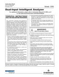
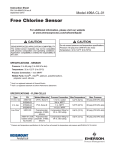
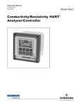
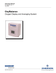
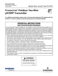
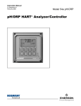
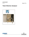
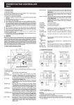
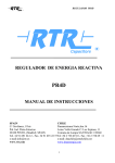
Instruction Sheet
PN 51A-54epH/rev J
October 2010
Model 54e pH/ORP
pH/ORP HART Analyzer/Controller
®
For additional information, please visit our website
at www.emersonprocess.com/raihome/liquid/.
ESSENTIAL INSTRUCTIONS
WARNINGS
READ THIS PAGE BEFORE PROCEEDING!
RISK OF ELECTRICAL SHOCK
Rosemount Analytical designs, manufactures, and tests its products to meet many national and international standards. Because
these instruments are sophisticated technical products, you must
properly install, use, and maintain them to ensure they continue
to operate within their normal specifications. The following
instructions must be adhered to and integrated into your safety
program when installing, using, and maintaining Rosemount
Analytical products. Failure to follow the proper instructions may
cause any one of the following situations to occur: Loss of life;
personal injury; property damage; damage to this instrument; and
warranty invalidation.
• Read all instructions prior to installing, operating, and servicing
the product. If this Instruction Manual is not the correct manual, telephone 1-949-757-8500 and the requested manual will
be provided. Save this Instruction Manual for future reference.
• If you do not understand any of the instructions, contact your
Rosemount representative for clarification.
• Follow all warnings, cautions, and instructions marked on and
supplied with the product.
• Inform and educate your personnel in the proper installation,
operation, and maintenance of the product.
• Install your equipment as specified in the Installation
Instructions of the appropriate Instruction Manual and per
applicable local and national codes. Connect all products to the
proper electrical and pressure sources.
• To ensure proper performance, use qualified personnel to
install, operate, update, program, and maintain the product.
• When replacement parts are required, ensure that qualified
people use replacement parts specified by Rosemount.
Unauthorized parts and procedures can affect the product’s
performance and place the safe operation of your process at
risk. Look alike substitutions may result in fire, electrical
hazards, or improper operation.
• Ensure that all equipment doors are closed and protective covers are in place, except when maintenance is being performed
by qualified persons, to prevent electrical shock and personal
injury.
Making cable connections to and servicing this instrument require access to shock hazard level voltages
which can cause death or serious injury, therefore,
disconnect all hazardous voltage before accessing
the electronics.
Relay contacts made to separate power sources
must be disconnected before servicing.
Electrical installation must be in accordance with the
National Electrical Code (ANSI/NFPA-70) and/or
any other applicable national or local codes.
Unused cable conduit entries must be securely
sealed by non-flammable closures to provide enclosure integrity in compliance with personal safety and
environmental protection requirements. Use NEMA
4X or IP65 conduit plugs supplied with the instrument
to maintain the ingress protection rating (IP65).
For safety and proper performance this instrument
must be connected to a properly grounded threewire power source.
Proper relay use and configuration is the responsibility of the user. No external connection to the
instrument of more than 60VDC or 43V peak
allowed with the exception of power and relay terminals. Any violation will impair the safety protection
provided.
Do not operate this instrument without front cover
secured. Refer installation, operation and servicing
to qualified personnel.
WARNING
This product is not intended for use in the residential, commercial or light industrial environment per
certification to EN50081-2.
MODEL 54e pH/ORP
SPECIFICATIONS
PHYSICAL SPECIFICATIONS – GENERAL
Enclosure: Epoxy-painted aluminum
NEMA 4X (IP65)
144 X 144 X 131 mm, DIN size (5.7 X 5.7 X 5.2 in.)
Front Panel: Membrane keyboard with tactile
feedback and user selectable security. Light gray,
blue and white overlay
Light gray enclosure, dark gray bezel
Display: Back-lit dot matrix LCD (7.0 x 3.5 cm),
blue on gray-green
The display contrast is compensated for ambient
temperature.
Relay Contacts: Relays 1-3: Epoxy sealed form A
contacts, SPST, normally open
Relay 4: Epoxy sealed form C, SPDT
28 Vdc
115 Vac
230 Vac
Resistive
5.0 Amps
5.0 Amps
5.0 Amps
Inductive
3.0 Amps
3.0 Amps
1.5 Amps
Weight/Shipping Weight: 1.8 kg/2.3 kg (4 lb/5 lb)
Process Variable Character Height: 16mm (0.6 in.)
Electrical Classification:
Class I, Division 2, Groups A, B, C, & D.
T5 Ta=50°C. Dust ignition proof: Class II,
Division 1, Groups E, F, & G; Class III.
CSA-LR34186:
Max. relay contact rating: 28 Vdc; 110 Vac;
230 Vac; 6 amps resistive
FM: Max. relay contact rating: 28 Vdc resistive
150 mA - Groups A & B;
400 mA - Group C;
540 mA - Group D
Power:
Code -01: 100 - 127 VAC, 50/60 Hz ± 6%, 6.0 W
200 - 253 VAC, 50/60 Hz ± 6%, 6.0 W
Code -02: 20 - 30 VDC, 6.0 W
Current Outputs: Output 1: pH, ORP, temperature,
glass impedance, or reference impedance.
Output 2: pH, ORP, temperature, glass impedance,
or reference impedance.
Each output is galvanically isolated, 0-20 mA or
4-20 mA into 500 ohms maximum load at 24 Vdc
or 115/230 Vac or 500 ohms maximum load at
100/200 Vac. Output 1 includes digital signal
4-20 mA superimposed HART (Code -09 only).
INSTRUMENT SPECIFICATIONS @ 25°C
— pH
Measurement Range: 0 to 14 pH
Output Scale Expansion: Zero suppression: up to 13
pH units
Span: Any pH from 1 to 14
Accuracy: ± 0.01 pH
Repeatability: ± 0.01 pH
Stability: ± 0.01 pH/month, non-cumulative
Temperature Coefficient: Input: ± 0.003 pH/°C
Output: ± 0.006 pH/°C
Temperature Compensation: Pt 100 or Pt 1000 RTD,
Automatic or Manual; –15 to 120°C (5 to 248°F)
INSTRUMENT SPECIFICATIONS @ 25°C
— ORP
Measurement Range: –1400 to +1400 mV
Output Scale Expansion: Zero suppression: up to
±1300 mV
Span: Any ORP range from 100 to 2800 mV
Accuracy: ± 1.0 mV
RFI/EMI: EN-61326
Repeatability: ± 1.0 mV
LVD (Code -01 only): EN-61010-1
Sira MC070111/00
Stability: ± 1.0 mV/month, non-cumulative
Ambient Temperature: 0 to 50°C (32 to 122°F)
NOTE: The analyzer is operable from -20 to 60°C
(-4 to 140°F) performance.
Temperature Coefficient: Input: ± 0.2 mV/°C
Output: ± 0.4 mV/°C
Relative Humidity: 95%, non condensing
Temperature Measurement: –15 to 120°C (5 to 248°F)
Pt 100 or Pt 1000 RTD
Alarms:
Relay 1 - Process, Interval, or Time Proportional
Control (TPC requires code -20)
Relay 2 - Process, Interval, or Time Proportional
Control (TPC requires code -20)
Relay 3 - Process, Interval, or Time Proportional
Control (TPC requires code -20)
Relay 4 - Sensor/analyzer and process fault alarm
Each relay has a dedicated LED on the front
panel.
3
MODEL 54e pH/ORP
WARNING
All electrical installation must conform to the National
Electrical Code, all state and local codes, and all plant
codes and standards for electrical equipment. All electrical installations must be supervised by a qualified and
responsible plant electrician.
INSTALLATION
Pipe Mounting:
1.
Attach the mounting bracket to the rear of the controller and
tighten the four screws.
2.
Place supplied U bolts around the mounting pipe and
through the pipe mounting bracket and mounting bracket.
Tighten the U bolt nuts until the controller is securely mounted to the pipe.
LOCATING THE CONTROLLER
Position the Model 54e pH/ORP controller to minimize the effects
of temperature extremes and to avoid vibration and shock.
Locate the controller away from your chemical process to protect
it from moisture and fumes.
Select an installation site that is more than 2 ft from high voltage
conduit, has easy access for operating personnel, and is not
exposed to direct sunlight.
UNPACKING AND INSPECTION
Inspect the exterior of the shipping container for any damage.
Open the container and inspect the controller and related hardware for missing or damaged parts.
If there is evidence of damage, notify the carrier immediately. If
parts are missing, contact Rosemount Analytical customer support.
Panel Mounting:
The controller is designed to fit into a 5.43 x 5.43 inch (DIN standard 144x144 mm) panel cutout (shown below). Installation
requires both front and rear access.
1.
Install the controller as shown below. Insert the instrument
enclosure through the front of the panel cutout and align the
panel mounting brackets as shown.
2.
Insert two mounting bracket screws through each of the two
mounting brackets and into the tapped holes in the rear of the
controller enclosure and tighten each screw.
3.
Insert four panel mounting screws through each hole in the
mounting brackets. Tighten each screw until the mounting
bracket holds controller firmly in place. To avoid damaging
the controller mounting brackets, do not use excessive force.
MECHANICAL INSTALLATION
Mounting the Controller
The Model 54e pH/ORP controller may be supplied with a mounting bracket accessory. If you use the mounting bracket on wall or
pipe installations, avoid mounting on pipes which vibrate or are
close to the process. The bracket may be modified to mount the
controller on I-beams or other rigid members. You can also fabricate your own bracket or panel mount the controller using the
bracket as an example.
Wall or Surface Mounting:
1.
Mount the bracket to the controller using the supplied four
screws.
2.
Mount controller mounting bracket to wall using any appropriate fastener such as screws, bolts, etc
PANEL MOUNTING
4
WALL MOUNTING
PIPE MOUNTING
MODEL 54e pH/ORP
All menus shown. Some menus will
change or not appear with different
settings.
MENUS
5
MODEL 54e pH/ORP
QUICK START
MODEL 54e pH/ORP QUICK START
Use the ↓ or � key to move the cursor down or up and
the → or ← to move the cursor right or left.
Press ENTER (F4) to move to the next menu, SAVE
(F4) to store a setting, EDIT (F4) to change a setting,
and EXIT (F1) to exit without saving changes.
STEP 1 - MEASUREMENT TYPE
Note: The analyzer is factory configured for a pH sensor. Skip to step 2 if you will be measuring pH.
Press any button. he main menu will appear with CALIBRATE highlighted.
Use the arrow buttons to select Program. Press
ENTER.
STEP 3 - AUTOCAL
Note: Obtain two pH buffer solutions with values at least
2 pH units apart. (Factory set buffers are 4.01, 7.00,
and 10.01 pH.)
Press any button. The main menu will appear with CALIBRATE highlighted. Press ENTER.
BUFFER CALIBRATION will be highlighted. Press
ENTER.
Place the sensor in the first buffer and press CONT.
Wait until the screen reads "Buf 1 done."
Use the arrow buttons to select the correct buffer.
Press CONT.
Rinse and dry the sensor.
Use the arrow buttons to select Configure. Press
ENTER.
Place the sensor in the second buffer and press CONT.
Wait until the screen reads "Buf 2 done."
DISPLAY will be highlighted. Press ENTER.
Use the arrow buttons to select the correct buffer.
Press CONT.
MEASURE will be highlighted. Press ENTER.
Use the arrow buttons to select REDOX or ORP. Press
SAVE.
Press EXIT until the main display appears.
Press EXIT until the main display appears.
STEP 4 - SINGLE-POINT
STANDARDIZATION
STEP 2 - OUTPUT SETPOINTS
After the sensor is installed, take a grab sample as
close to the sensor as possible.
Press any button. The main menu will appear with CALIBRATE highlighted.
Use the arrow buttons to select Program. Press
ENTER.
Use the arrow buttons to select OUTPUT SETPOINTS.
Press ENTER.
OUTPUT 1 SETPOINTS will be highlighted. Press
ENTER. Press CONT.
4 mA will be highlighted. Press EDIT. Use the arrow buttons to enter the desired value. Press SAVE.
Use the arrow buttons to select 20 MA. Press EDIT.
Use the arrow buttons to enter the desired value. Press
SAVE. Press EXIT.
Use the arrow buttons to select OUTPUT 2 SETPOINTS. Press ENTER. Press CONT.
Enter the 4 mA and 20 mA values as above.
Press EXIT until the main display appears.
6
Use a calibrated pH instrument with automatic temperature compensation to determine the pH of the grab sample.
Press any button. The main menu will appear with CALIBRATE highlighted. Press ENTER.
Use the arrow buttons to select STANDARDIZE. Press
ENTER.
Press EDIT. Use the arrow buttons to enter the pH
value of the sample. Press SAVE.
Press EXIT until the main display appears.
MODEL 54e pH/ORP
WIRING
Sensor Wiring Diagram
7
Power Input and Relay Output Wiring for Model 54e pH/ORP
The right people,
the right answers,
right now.
ON-LINE ORDERING NOW AVAILABLE ON OUR WEB SITE
http://www.raihome.com
Specifications subject to change without notice.
8
Credit Cards for U.S. Purchases Only.
Emerson Process Management
2400 Barranca Parkway
Irvine, CA 92606 USA
Tel: (949) 757-8500
Fax: (949) 474-7250
http://www.raihome.com
© Rosemount Analytical Inc. 2010