1
Instruction Sheet
LIQ_MAN_ABR_6081-P
6081-P
October 2013
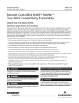
6081-P
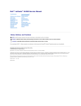
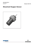
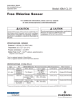
Wireless pH/ORP Transmitter
Figure 1. 6081-P
Essential Instructions – Read this before proceeding
Rosemount Analytical designs, manufactures, and tests its products to meet many national and international standards.
Because these instruments are sophisticated technical products, you must properly install, use, and maintain them to
ensure they continue to operate within their normal specifications. The following instructions must be adhered to and
integrated into your safety program when installing, using, and maintaining Rosemount Analytical products. Failure
to follow the proper instructions may cause any one of the following situations to occur: Loss of life; personal injury;
property damage; damage to this instrument; and warranty invalidation.
• Read all instructions prior to installing, operating, and servicing the product. If this Instruction Manual is not the
correct manual, telephone 1-800-654-7768 and the requested manual will be provided. Save this Instruction Manual
for future reference.
• If you do not understand any of the instructions, contact your Rosemount representative for clarification.
• Follow all warnings, cautions, and instructions marked on and supplied with the product.
• Inform and educate your personnel in the proper installation, operation, and maintenance of the product.
6081-P
October 2013
Instruction Sheet
LIQ_MAN_ABR_6081-P
Essential Instructions (continued)
• Install your equipment as specified in the Installation Instructions of the appropriate Instruction Manual and per
applicable local and national codes. Connect all products to the proper electrical and pressure sources.
• To ensure proper performance, use qualified personnel to install, operate, update, program, and maintain the product.
• When replacement parts are required, ensure that qualified people use replacement parts specified by Rosemount.
Unauthorized parts and procedures can affect the product’s performance and place the safe operation of your process at
risk. Look alike substitutions may result in fire, electrical hazards, or improper operation.
• Ensure that all equipment doors are closed and protective covers are in place, except when maintenance is being
performed by qualified persons, to prevent electrical shock and personal injury.
Note
The Rosemount 6081 and all other wireless devices should be installed only after the 1420 Wireless Gateway has been installed
and is functioning properly. Wireless devices should also be powered up in order of proximity from the 1420 Wireless Gateway,
beginning with the closest. This will result in a simpler and faster network installation.
Note
Shipping considerations for wireless products (Power Modules):
The unit was shipped to you without the power module installed. Please remove the power modules from the unit prior to
shipping.
Primary lithium power modules are regulated in transportation by the U. S. Department of Transportation, and are also covered
by IATA (International Air Transport Association), ICAO (International Civil Aviation Organization), and ARD (European Ground
Transportation of Dangerous Goods). It is the responsibility of the shipper to ensure compliance with these or any other local
requirements. Please consult current regulations and requirements before shipping.
The power module with the wireless unit contains two “C” size primary lithium/thionyl chloride power sources.
Each power module contains approximately 5 grams in each pack. Under normal conditions, the power module materials
are self-contained and are not reactive as long as the power modules and the pack integrity are maintained. Care should
be taken to prevent thermal, electrical or mechanical damage. Contacts should be protected to prevent premature
discharge.
Power module hazards remain when cells are discharged. Power modules should be stored in a clean and dry area. For
maximum power module life, storage temperature should not exceed 30 °C.
WARNING
Use only with Rosemount Smart Power Module PN 701PBKKF
WARNING
Potential Electrostatic Hazard – The plastic antenna may present a potential electrostatic ignition hazard and must not be rubbed
or cleaned with a dry cloth.
WARNING
Mechanical Spark Hazard – The 6081 enclosure is made of aluminum alloy and given a protective polyurethane paint finish.
However, care should be taken to protect it from impact or abrasion if located in Zone 0.
This applies to any Intrinsically Safe installation, whether the Class, Division or Zone system is used.
2
Instruction Sheet
LIQ_MAN_ABR_6081-P
6081-P
October 2013
Quick Start Guide - 6081 Wireless pH Transmitter
1. Install the Power Module inside the rear enclosure. Follow the installation instructions on p.9 “Power Module
Installation”.
2. Wire the pH or ORP sensor to the transmitter. Refer to the sensor instruction sheet for details.
3. Once the connections are secure and verified, install the Power Module to power to the transmitter.
4. When the transmitter is powered up for the first time, Quick Start screens appear. Using Quick Start is easy.
a. A blinking field shows the position of the cursor.
b. Use the or key to move the cursor left or right. Use the or key to move the cursor up or down or to
increase or decrease the value of a digit. Use the or key to move the decimal point.
c. Press ENTER to store a setting. Press EXIT to leave without storing changes. Pressing EXIT also returns the
display to the previous screen.
5. Choose a local language.
6. Choose measurement: pH, ORP, or Redox.
7. Choose preamplifier location. Select Xmtr to use the integral preamplifier in the transmitter.
8. Choose Off or On for displayed diagnostics.
9. Select measurement update rate. Select ENTER to choose an update rate of 1 minute or enter a value from 1 second to
10 minutes.
10. Choose temperature units: °C or °F
11. Choose Yes to Setup the Wireless Network or No if the Network ID and the Join Key have already been entered.
12. Enter the 5-digit Wireless Network ID. This ID number must match the Network ID of the 1420 Wireless Gateway.
13. Enter the 8-digit Network Join Key number 1 of 4 to match the 1420 Wireless Gateway. See the Note below for
clarification.
14. Enter Network Join Key numbers 2, 3, and 4 to match the 1420 Wireless Gateway.
15. The transmitter will exit Quick Start and display the live measurement screen.
16. To change the Network ID or Join Key, HART address, or measurement-related settings from the default values, and
to set security codes, press MENU. Select Program and follow the prompts. Refer to the appropriate menu tree.
17. To return the transmitter to default settings, choose Reset Analyzer in the Program menu.
Note regarding Wireless Device Configuration
In order to communicate with the 1420 Wireless Gateway, and ultimately the Information System, the transmitter must
be configured to communicate with the wireless network. This step is the wireless equivalent of connecting wires from a
transmitter to the information system.
Using a Field Communicator or AMS, enter the Network ID and Join Key so that they match the Network ID and Join Key
of the gateway and other devices in the network. The Network Join Key consists of four (4) blocks, each with an eight
digit code. The code of each block must match its corresponding block in the 1420 in order for the 6081 to join the
network.
If the Network ID and Join Key are not identical, the transmitter will not communicate with the network. The Network ID
and Join Key may be obtained from the 1420 Wireless Gateway on the Setup>Network>Settings page on the web server.
The final device network configuration piece is the Update Rate. This by default is one (1) minute. This may be changed at
commissioning, or at any time via AMS or the 1420 Wireless Gateway’s web server. The Update Rate should be between 1
second and 10 minutes.
When device configuration is completed, remove the power module and replace the rear cover of the transmitter until
the time of actual live installation in the process. Tighten the cover to the proper tension for safety approvals.
Note
For installation and operation at high elevations, slight convex bulging of the front keypad overlay is possible. If bulging occurs, it
is recommended to unscrew the two Philips head screws that faster the front cover to the central housing to release any internal
pressure. This will equalize the device’s internal pressure to the ambient atmospheric pressure. Re-tighten the two Philips head
screws to secure the front cover before device installation or operation. Make sure to perform the pressure equalization in a clean,
dry area.
3
6081-P
October 2013
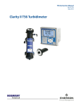
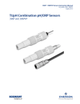
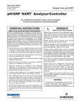
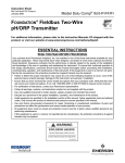
Figure 2. Menu Tree for 6081 pH Wireless Transmitter
4
Instruction Sheet
LIQ_MAN_ABR_6081-P
Instruction Sheet
LIQ_MAN_ABR_6081-P
6081-P
October 2013
Product Description
When used with appropriate sensors, the 6081-P can measure pH or ORP (oxidation reduction potential) of a liquid and
transmit data wirelessly with a radio transceiver which uses HART 7 communication protocol. The instrument has a
local operator interface consisting of a keyboard and LCD display which can be used to observe process parameters or to
configure the 6081. This instrument is available with approvals for use in hazardous areas.
General Specifications
Enclosure: Cast aluminum. NEMA 4X, IP66
Dimensions: 6.55” x 5.40” x 5.15” (166mm x 137mm x 131mm)
Conduit Openings: ¾” FNPT
Ambient Temperature: -4 to 149 °F (-20 to 65 °C)
Storage Temperature: -22 to 158 °F (-30 to 70 °C)
Relative Humidity: 0 to 95% (non-condensing)
Weight/Shipping Weight: 7 lbs/8 lbs (3.2/3.6 kg)
Digital Communications: HART 7 Wireless HART™
Functional Specifications
pH Range: 0 to 14
ORP Range: -1400 to +1400mV
Compatible with Rosemount Analytical SMART pH sensors
Calibrations/standardization: The automatic buffer recognition uses stored buffer values and their temperature curves
for the most common buffer standards available worldwide. The transmitter also performs a stabilization check on the
sensor in each buffer.
A manual two-point calibration is made by immersing the sensor in two different buffer solutions and entering the pH
values. The microprocessor automatically calculates the slope which is used for self-diagnostics. An error message will
be displayed if the pH sensor is faulty. This slope can be read on the display and/or manually adjusted if desired. An online one-point process standardization is accomplished by entering the pH or ORP value of a grab sample.
The following calibration methods are supported:
- Two point calibration with Low and High buffer (pH only)
- Two point calibration with Automatic Buffer recognition (pH only)
- Single point standardization
- Single point Temperature Adjustment
- Automatic calibration upon live connection to RAI SMART pH sensors and upload of stored cal data to transmitter
Automatic Temperature Compensation: External 3-wire Pt100 RTD or Pt1000 RTD located in the sensor, compensates
the pH reading for temperature fluctuations. Compensation covers the range -10 to 150 °C (14 to 302 °F). Manual
temperature compensation is also selectable.
Accuracy: ±1 mV @ 25 °C ±0.01 pH
Repeatability: ±1 mV @ 25 °C ±0.01 pH
Information and Status: Information screens display faults and warnings, radio transmission status, network ID number,
Power Module voltage, transmitter model, and software version.
Diagnostics: The internal diagnostics can detect:
RTD Failure
Glass Low Failure
Glass High Failure
Broken Glass Fault
Reference High Failure
CPU Error
High Temperature Warning
Low Temperature Warning
Glass Impedance High Warning
Glass Impedance Low Warning
Reference Impedance High Warning
5
6081-P
October 2013
Instruction Sheet
LIQ_MAN_ABR_6081-P
EEPROM Warning
Sense Line Open Warning
Factory Cal Warning
Keyboard Warning
Once a fault or warning is detected, the display will show a message describing the problem.
Sensor Temperature Range: -10 to 150°C (PT100 and PT1000)
Display: 2-line, 16 character display supports display of pH and mV units. Display shows temperature.
Approvals:
RFI/EMI:
EN-61326
EN 301 489-1 V1.2 2002
EN 301 489-17: V1.4.1 2002
EN 60950-1: 2001
EN 300 328 V 1.6.1 (2004-11)
Hazardous Location Approvals
Intrinsic Safety:
Special Conditions of Use:
1. The 6081 enclosure is made of aluminum alloy and
given a protective polyurethane paint finish; however,
care should be taken to protect it from impact or
abrasion if located in zone 0. This applies to any
Intrinsically Safe installation, whether the Class, Division
or Zone system is used.
2. Potential Electrostatic Hazard – The plastic antenna may
present a potential electrostatic ignition hazard and
must not be rubbed or cleaned with a dry cloth.
Intrinsically Safe,
Class I, Division 1
Groups ABCD/T4
Ta = -20 °C to +65 °C – 1400322;
IP66
Class 1 Zone 0, AEx ia IIC T4
Ta = -20 °C to +65 °C – 1400322;
IP66
Complies with FM standards:
FM3600:1998
FM3610: 2010, ISA60079-0:2009, ISA60079-11:2009.
FM3611: 2004
FM3810: 2005
ANSI/IEC 60529:2004
Class I, Division 1, Groups A/B/C & D
Class II, Division 1, Groups E/F& G
Class III
T4 Tamb : -20 to +65 °C
Type 4x, IP66
CE 1180 II1G
Baseefa 10 ATEX 0149X
Ex ia IIC T4 Ga (-20 °C ≤ Ta ≤ +65 °C
(source CE cert-6081 Baseefa)
Complies with Standards: EN
60079-0:2009, EN 60079-11:2007
Non-Incendive:
Nonincendive, Class I,
Division 2, Groups ABCD/T4
Ta = -20˚C to +65 °C
Class I, Division 2,
Groups A, B, D
Dust Ignition Proof
Class II, Division 2,
Groups F & G
T4 Tamb : -20 to +65 °C
Environmental: The operating atmosphere of the
transmitter must be consistent with the appropriate
hazardous location certifications.
6
Instruction Sheet
LIQ_MAN_ABR_6081-P
6081-P
October 2013
pH Calibration Procedure – Auto Buffer Calibration
1. Obtain two buffer solutions. Ideally, the buffer values should bracket the range of pH values to be measured.
2. Remove the pH sensor from the process liquid. If the process and buffer temperatures are appreciably different place
the sensor in a container of tap water at the buffer temperature. Do not start the calibration until the sensor has reached
the buffer temperature. Thirty minutes is usually adequate.
3. Press MENU. The main menu appears. Choose Calibrate.
4. Choose pH.
5. Choose BufferCal.
6. Choose Auto.
7. To continue with the calibration, choose Buffer1.Then go to step 8. To change stability criteria, choose Setup and go to
step 19.
8. Rinse the sensor with water and place it in buffer 1. Be sure the glass bulb and the reference junction are completely
submerged. Swirl the sensor.
9. The screen at left is displayed with “Wait” flashing until the reading is stable. The default stability setting is <0.02
pH change in 10 sec. To change the stability criteria, go to step 19. When the reading is stable, the screen in step 10
appears.
10. The top line shows the actual reading. The transmitter also identifies the buffer and displays the nominal buffer value
(buffer pH at 25 °C). If the displayed value is not correct press ▼ or ▲ to display the correct value. The nominal value
will change, for example from 7.01 to 6.86 pH. Press ENTER to store.
11. The screen at left appears momentarily.
12. The screen at left appears. Remove the sensor from Buffer 1, rinse it with water, and place it in Buffer 2. Be sure the
glass bulb and the reference junction are completely submerged. Swirl the sensor. Choose Buffer2.
13. The screen is displayed with “Wait” flashing until the reading is stable. When the reading is stable, the screen in step
14 appears.
14. The top line shows the actual reading. The transmitter also identifies the buffer and displays the nominal buffer value
(buffer pH at 25 °C). If the displayed value is not correct, press ▼ or ▲ to display the correct value. The nominal value
will change, for example from 9.91 to 10.02 pH. Press ENTER to store.
15. The screen at the left appears momentarily.
16. If the calibration was successful, the transmitter will display the offset and slope (at 25°). The display will return to the
screen in step 6.
17. If the slope is out of range (less than 45 mV/pH or greater than 60 mV/pH) or if the offset exceeds the value
programmed in Section 8.4, an error screen appears. The display then returns to the screen in step 6.
18. To return to the main display, press MENU then EXIT.
19. Choosing Setup in step 7 causes the Buffer Stabilize screen to appear. The transmitter will not accept calibration data
until the pH reading is stable. The default requirement is a pH change less than 0.02 units in 10 seconds. To change
the stability criteria:
a. Enter the desired stabilization time
b. Enter the minimum amount the reading is permitted to change in the time specified in step 19a.
20. To return to the main display, press MENU then EXIT.
7
6081-P
October 2013
Instruction Sheet
LIQ_MAN_ABR_6081-P
Sensor Wiring
Note
For additional wiring information on this product, including sensor combinations not shown here, please refer to either our online
wiring programs or the Manual DVD enclosed with each product.
1056, 1057, 56, 5081, 6081, 54e, and XMT :
http://www3.emersonprocess.com/raihome/sp/liquid/wiring/XMT/ 1066 and sensors with SMART preamps:
http://www2.emersonprocess.com/en-US/brands/rosemountanalytical/Liquid/Sensors/Pages/ Wiring_Diagram.aspx
1055:
http://www3.emersonprocess.com/raihome/sp/liquid/wiring/1055/
General Information
pH and ORP sensors without preamps manufactured by Rosemount Analytical can be wired directly to the 6081-P
wireless transmitter.
Sensor Wiring
To assist in sensor wiring, please refer to the one of the following resources:
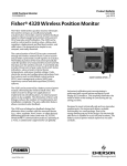
1. Sensor Instruction Sheet – provided with each shipped sensor. Detailed wiring drawings show terminal block
connections for each sensor lead.
2. Online wiring program available at http://www.emersonprocess.com/raihome/liquid/products/wiring/Xmt displays
wiring schematics for all compatible pH sensors.
Note
All sensor wiring must be rated for ≥70 °C.
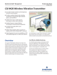
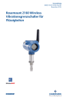
The following drawing identifies each terminal block lead position for pH sensors.
Figure 3. 6081 Sensor Wiring and Connection Points
8
Instruction Sheet
LIQ_MAN_ABR_6081-P
6081-P
October 2013
Power Module Installation / Replacement
The expected life of the power module (PN 701PBKKF) is a minimum of four years at reference conditions. This section
describes the procedure for initial installation and replacement of the power module (PN 701PBKKF). The new power
module should be stored in a safe place with a controlled environment until the 6081 is ready for live operation. Note that
the power module is packed separately from the 6081 wireless transmitter upon delivery and must be installed initially.
For initial installation or replacement of the power module, follow these steps using a Philips-head screwdriver:
1. Unscrew the two long machine screws to remove the rear cover of the 6081. Separate the rear cover from the central
housing by manually prying the sections apart. Do not use screwdrivers or tools to separate these housing parts. The
parts are sealed with an o-ring.
2. Before installation, note the safety warning, disposal instructions and part information on the connection side label of
the power module.
3. With the 6081 front display section facing away from you, align the power module pack with the curved surface of
the pack facing towards you and the small protruding connector facing away from you. Make sure to align the power
module and its keyed connector with the connection receptacle in the middle of the instrument’s terminal block area.
4. With gentle pressure, insert the keyed connector on the power module into the receptacle (labeled Power Module
Connection on the drawing). The power module seats in the connection receptacle with an o-ring.
5. Confirm that the power module is fully inserted in the receptacle and properly aligned with the surrounding terminal
block.
6. Replace the rear cover of the 6081 with the two screws to secure it to the central housing. Tighten screws and verify
operation. Correct installation the rear cover will ensure that the power module is properly secured to power the
transmitter.
7. DO NOT RETURN SHIP THE USED POWER MODULE to Rosemount Analytical. Dispose of spent power modules as a
hazardous material in accordance with government regulations.
WARNING
Use only with Rosemount SMART Power Module (PN 701PBKKF)
9
6081-P
October 2013
Instruction Sheet
LIQ_MAN_ABR_6081-P
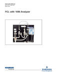
Mounting
Mounting on a Flat Surface
Figure 4. Wall Mounting Installation for 6081.
Use Pipe/Wall Mounting Bracket Kit, PN23820-00
Note: PN 23820-00 mounting bracket kit includes mounting hardware for pipe mounting only. Wall mounting hardware to be provided by customer. Only use suitable fasteners and hardware to securely fasten the bracket and transmitter to the wall surface
10
Instruction Sheet
LIQ_MAN_ABR_6081-P
6081-P
October 2013
Pipe Mounting
The pipe mounting kit (PN 23820-00/01) accommodates 1–½ in. pipe
Figure 5. Pipe Mounting Installation for 6081.
Use Pipe/Wall Mounting Bracket Kit, PN23820-00
11
12
7
NORYL DISPLAY
FRAME PN 34175-00
ALUMINUM
FRONT COVER
PN 34180-00
2
LCD MODULE
PN 9010443
6
5
DISPLAY INTERFACE PCB
PN 24298-00
2X NEOPRENE O-RING
PN 9550344
(Mc MASTER-CARR PART NO. 4679T281
MADE OF BLACK BUNA-N,
-65°C TO +275°F COT)
FRONT NORYL LCD FRAME
PN 34163-00
POLYCARBONATE
INSULATOR
PN 34183-00
POLYCARBONATE
14 PIN RBBON CABLE
PN 24224-00
WIRELESS PCB W/2.4 GHz
HART 7 RADIO
PN 24295-00 OR
PN 24296-00
2X NEOPRENE
O-RING
PN 9550342
NORYL
PIN GUIDE
PN 34148-00
ALUMINUM BASE
2
PN 34181-00
3/4 -14NPT
4
LQD10112
ECO NO
APR 29, 10
RELEASE DATE
C
3
REV
THIS DRAWING HAS BEEN SUBMITTED
FOR HAZARDOUS LOCATION
APPROVAL. ANY CHANGES TO THIS
DRAWING REQUIRE AGENCY
APPROVAL.
FINISH
MATERIAL
2
THIS FILE CREATED USING
SOLID EDGE
ENG APPR S. PACIS
CHECKED J. PERKINS
DATE
DATE
4-30-10
4-30-10
5-1-08
Emerson
WEIGHT:
1
1700672
SIZE DWG NO
SCALE: 1:1
D
D
SHEET 1 OF 1
REV
ANALYTICAL
ROSEMOUNT
CERT PROD, MODEL
6081 XMTR I.S. (FM)
PROCESS MANAGEMENT
2
ALUMINUM
REAR COVER
PN 34182-00
JP/ SP
CHECKED/APPROVED
POLYURETHANE
RING PN 9160626
6.55
166.44
TITLE
1
CH 5-18-11
BY
ALUMINUM WAVE RING
PN 9160627
OVERALL DIMENSIONS
B. JOHNSON
APPROVALS
DRAWN
O 4.80
121.92
DIMENSIONS ARE IN INCHES
REMOVE BURRS & SHARP EDGES
MACHINE FILLET RADII .020 MAX
NOMINAL SURFACE FINISH: 125
ANGLES ± 1/2°.
.XX ± .03 .XXX ± .010
REVISION
DESCRIPTION
NORYL BUSHING
PN 9160630
2
NEOPRENE SPACER RING
PN 34149-00
LQD10215 SEE ECO
ECO
POWER MODULE
PN 00753-9220-0001
D
LTR
MYLAR WIRING DIAGRAM LABEL
PN 9241688-00
REVISIONS NOT PERMITTED
W/O AGENCY APPROVAL
REV
REV
REV
REV
REV
REV
POLYESTER AGENCY
CERTIFICATION LABEL
PN 9241685-01
SILICONE PIN SEAL
PN 34150-00
OPTIONALLY INSTALLED ALUMINUM
OR BRASS PLUG WITH TEFLON TAPE
(2X)
D1
NEOPRENE
O-RING
PN 9550343
NORYL TERMINAL
INSULATOR
PN 34146-00
INTERFACE PCB
PN 24356-00 OR
PN 24357-00
3
THIS DOCUMENT IS
CERTIFIED BY
A
B
C
8
POLYESTER
KEYPAD/OVERLAY
PN 34259-00
D2
WINDOW, FILLER
PN 34255-00
RETAINER, LCD
PN 34254-00
ASSEMBLY LOCATION
('ASSEMBLED IN MEXICO'
OR 'MADE IN USA')
MODEL NUMBER
POLYCARBONATE
ANTEENA
PN 9160628
NORYL TERMINAL
BLOCK PN 34145-00
MARKED AS 6081-A-BB-CCC
WHERE:
A = P (pH) OR C (CONDUCTIVITY)
BB = 67 (FM APPROVED)
CCC = ANY 3 DIGIT NUMBER (COUNTRY CODE)
4
October 2013
A
B
AGENCY CERTIFICATION LABEL
SERIAL NUMBER INCLUDES DATE CODE
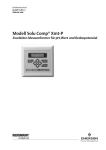
THE PAINT ON THE OUTER SURFACE OF THE ENCLOSURE IS LESS THAN 0.2mm THICK.
4.
5
APPROVED MODELS
POLYCARBONATE
ADAPTER
PN 9160629
ENCLOSURE MEETS THE REQUIREMENTS OF IP66.
3.
OPTIONAL
SPECTRUM APPROVAL
INFORMATION
ALUMINUM FRONT COVER, ALUMINUM BASE AND ALUMINUM REAR COVER ARE MADE OF ALUMINUM
356C OR ALUMINUM ALLOY A413.0 OR ALUMINUM ALLOY A3600.0. THESE MATERIALS CONTAIN LESS THAN
6 % MAGNESSIUM. PAINT MANUFACTURER: CADINAL, PART NO. 6442, BLUE.
PCB MATERIALS HAVE CTI > 175. ALL OTHER INSULATING MATERIALS HAVE CTI >100.
6
2
1.
NOTES: UNLESS OTHERWISE SPECIFIED
7
D 1700672
C
D
8
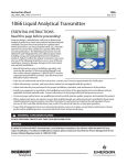
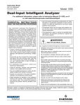
This document contains information proprietary to
Rosemount Analytical, and is not to be made available
to those who may compete with Rosemount Analytical.
6081-P
LIQ_MAN_ABR_6081-P
Instruction Sheet
Figure 6. FM IS Installation
A
B
8
SW VER#
NORYL
DISPLAY
FRAME
2X NEOPRENE O-RING
7
2
6
LCD MODULE
FRONT NORYL
LCD FRAME
POLYCARBONATE
INSULATOR
POLYCARBONATE
ADAPTER
DISPLAY INTERFACE PCB
PN 24298-00
WIRELESS PCB
W/2.4 GHz
HART 7 RADIO
PN 24295-00 OR
PN 24322-00
POLYCARBONATE
14 PIN RBBON CABLE
9241685-02/B
POLYCARBONATE
ANTENNA
5
5
NEOPRENE
O-RING
6081-P-69-XXX
6081-C-69-XXX
D1
4
2
REV
REV
REV
REV
REV
REV
LQD10154
ECO NO
MAY 21, 10
RELEASE DATE
C
3
REV
FINISH
MATERIAL
NEOPRENE
SPACER RING
REVISION
ALUMINUM
WAVE RING
DESCRIPTION
2
THIS FILE CREATED USING
SOLID EDGE
DATE
5-9-10
5-5-10
5-5-08
DATE
6.55
166.44
Emerson
SCALE: 1:1
WEIGHT:
1
1700673
SIZE DWG NO
D
D
SHEET 1 OF 1
REV
ANALYTICAL
ROSEMOUNT
ALUMINUM
REAR COVER
2
JP/DOC
CHECKED/APPROVED
CERT PROD, MODEL
6081 XMTR I.S.(CSA)
PROCESS MANAGEMENT
TITLE
1
CH 5-18-11
BY
POLYURETHANE
RING
OVERALL DIMENSIONS
ENG APPR D, CROWLEY
CHECKED C. HOANG
J. PERKINS
APPROVALS
DRAWN
O 4.80
121.92
DIMENSIONS ARE IN INCHES
REMOVE BURRS & SHARP EDGES
MACHINE FILLET RADII .020 MAX
NOMINAL SURFACE FINISH: 125
ANGLES ± 1/2°.
.XX ± .03 .XXX ± .010
NORYL TERMINAL
BLOCK
NORYL TERMINAL
INSULATOR
2
NORYL BUSHING
LQD10215 SEE ECO
ECO
POWER MODULE
PN 00753-9920-0001
D
LTR
MYLAR WIRING
DIAGRAM LABEL
REVISIONS NOT PERMITTED
W/O AGENCY APPROVAL
THIS DRAWING HAS BEEN SUBMITTED
FOR HAZARDOUS LOCATION
APPROVAL. ANY CHANGES TO THIS
DRAWING REQUIRE AGENCY
APPROVAL.
OPTIONALLY INSTALLED ALUMINUM
OR BRASS PLUG WITH TEFLON TAPE
(2X)
ALUMINUM BASE
3/4-14NPT
3
THIS DOCUMENT IS
CERTIFIED BY
POLYESTER AGENCY
CERTIFICATION LABEL
SILICONE
PIN SEAL
WHERE XXX=COUNTRY CODE
EXAMPLE:108=BRAZIL
INTERFACE PCB
PN 24356-00 OR
PN 24357-00
2X NEOPRENE
O-RING
NORYL
PIN GUIDE
4
APPROVED MODELS
A
B
C
LIQ_MAN_ABR_6081-P
ALUMINUM
FRONT COVER
RETAINER, LCD
PN 34254-00
2:1
AGENCY CERTIFICATION LABEL
WINDOW, FILLER
PN 34255-00
POLYCARBONATE
OR POLYESTER
KEYPAD/OVERLAY
D2
S/N:
INTRINSICALLY SAFE FOR CLASS I, II & III, DIVISION 1,
®
GROUPS A, B, C, D, E, F & G
HAZARDOUS AREA WHEN CONNECTED PER DWG
-LR 34186
T4 Tamb = 65°C
DWG 1700673
NON-INCENDIVE CLASS I, DIVISION 2 GROUPS A, B, C & D
DUST IGNITION PROOF CLASS II AND III, DIVISION 1, GROUPS E, F & G
ENCLOSURE TYPE: NEMA 4/4X IP66
WARNING: COMPONENT SUBSTITUTION MAY IMPAIR INTRINSIC SAFETY
OR SUITABILITY FOR DIVISION 2
OUTPUT: WIRELESS HART (2.4 GHz) FCC ID: LW2RM2510 / IC ID: 2731A-RM2510 IS CONTAINED WITHIN.
SUPPLY:
USE ONLY WITH ROSEMOUNT SMART POWER MODULE P/N 753-9220-0001
MODEL 6081
ENCLOSURE MEETS THE REQUIREMENTS OF NEMA 4X AND IP66.
3.
D3
MATERIAL: ALUMINUM ALLOY CONTAINING LESS THAN 6% BY WEIGHT OF MAGNESIUM.
2
IN THIS AREA, PRINT:
1400335 IF 6081P,
1400336 IF 6081C
PCB MATERIALS HAVE CTI > 175. ALL OTHER INSULATING MATERIALS HAVE CTI >100.
6
1.
NOTES: UNLESS OTHERWISE SPECIFIED
7
D 1700673
C
D
8
This document contains information proprietary to
Rosemount Analytical, and is not to be made available
to those who may compete with Rosemount Analytical.
Instruction Sheet
October 2013
6081-P
Figure 7. CSA IS Installation
13
14
8
POLYCARBONATE
OR POLYESTER
KEYPAD/OVERLAY
NORYL
DISPLAY
FRAME
WINDOW, FILLER
PN 34255-00
7
2
2X NEOPRENE O-RING
FRONT NORYL
LCD FRAME
LCD MODULE
6
5
ALUMINUM BASE 2
3/4-14NPT
SILICONE
PIN SEAL
4
LQD10235
ECO NO
RELEASE DATE
3
REV
D
THIS DRAWING HAS BEEN SUBMITTED
FOR HAZARDOUS LOCATION
APPROVAL. ANY CHANGES TO THIS
DRAWING REQUIRE AGENCY
APPROVAL.
FINISH
MATERIAL
DIMENSIONS ARE IN INCHES
REMOVE BURRS & SHARP EDGES
MACHINE FILLET RADII .020 MAX
NOMINAL SURFACE FINISH: 125
ANGLES ± 1/2°.
.XX ± .03 .XXX ± .010
NORYL BUSHING
THIS FILE CREATED USING
SOLID EDGE
2
6.55
166.44
8-9-10
8-9-10
7-20-10
DATE
SCALE: 1:1
D
1
CHECKED/APPROVED
2
ALUMINUM
REAR COVER
DATE
WEIGHT:
1
1700674
D
SHEET 1 OF 1
REV
ANALYTICAL
ROSEMOUNT
CERT PROD, MODEL
6081 XMTR I.S.(ATEX)
SIZE DWG NO
TITLE
PROCESS MANAGEMENT
Emerson
OVERALL DIMENSIONS
ENG APPR D. CROWLEY
CHECKED J. PERKINS
C. HOANG
APPROVALS
DRAWN
O 4.80
121.92
BY
POLYURETHANE
RING
ALUMINUM
WAVE RING
REVISION
DESCRIPTION
NEOPRENE
SPACER RING
2
POWER MODULE
PN 00753-9220-0001
ECO
MYLAR WIRING
DIAGRAM LABEL
LTR
NORYL TERMINAL
BLOCK
POLYESTER AGENCY
CERTIFICATION LABEL
(SILVER POLYESTER
THERMfilm SELECT 22970)
AUG 10, 2010
REV
REV
REV
REV
REV
REV
REVISIONS NOT PERMITTED
W/O AGENCY APPROVAL
NORYL TERMINAL
INSULATOR
INTERFACE PCB
PN 24356-00 OR
PN 24357-00
OPTIONALLY INSTALLED ALUMINUM
OR BRASS PLUG WITH TEFLON TAPE
(2X)
NOTE: THE STATIC GUARD LAYER GROUNDING TAB IS SECURED
TO THE HOUSING USING INDICATED SCREW. THE STATIC GUARD
LAYER MUST BE < 0.2mm FROM TOP SURFACE OF OVERLAY.
ANY VOID AREA IN THE STATIC GUARD LAYER MUST BE < 4 cm²
DISPLAY INTERFACE PCB
PN 24298-00
NORYL
PIN GUIDE
2X NEOPRENE
O-RING
NEOPRENE
O-RING
POLYCARBONATE
ANTENNA
WHERE XXX=COUNTRY CODE
EXAMPLE:108=BRAZIL
6081-P-73-XXX
6081-C-73-XXX
3
THIS DOCUMENT IS
CERTIFIED BY
A
B
C
ALUMINUM
FRONT COVER
RETAINER, LCD
PN 34254-00
WIRELESS PCB
W/2.4 GHz
HART 7 RADIO
PN 24295-00 OR
PN 24296-00
MODEL NUMBER
POLYCARBONATE
ADAPTER
ASSEMBLY LOCATION
4
APPROVED MODELS
October 2013
A
B
5
OPTIONAL
SPECTRUM APPROVAL INFORMATION
POLYCARBONATE
14 PIN RBBON CABLE
POLYCARBONATE
INSULATOR
SERIAL NUMBER INCLUDES DATE CODE
AGENCY CERTIFICATION LABEL
ENCLOSURE MEETS THE REQUIREMENTS OF NEMA 4X AND IP66.
3.
OMIT THE IECEx NUMBER IF ONLY
ATEX APPROVAL IS WANTED.
PCB MATERIALS HAVE CTI > 175. ALL OTHER INSULATING MATERIALS HAVE CTI >100.
MATERIAL: ALUMINUM ALLOY CONTAINING LESS THAN 6% BY WEIGHT OF MAGNESIUM.
1.
6
2
NOTES: UNLESS OTHERWISE SPECIFIED
7
D 1700674
C
D
8
This document contains information proprietary to
Rosemount Analytical, and is not to be made available
to those who may compete with Rosemount Analytical.
6081-P
LIQ_MAN_ABR_6081-P
Instruction Sheet
Figure 8. ATEX IS Installation
Instruction Sheet
LIQ_MAN_ABR_6081-P
6081-P
October 2013
15
6081-P
October 2013
Instruction Sheet
LIQ_MAN_ABR_6081-P
facebook.com/EmersonRosemountAnalytical
AnalyticExpert.com
Credit Cards for U.S. Purchases Only.
twitter.com/RAIhome
youtube.com/user/RosemountAnalytical
©2013 Rosemount Analytical, Inc. All rights reserved.
Emerson Process Management
2400 Barranca Parkway
Irvine, CA 92606 USA
Tel: (949) 757-8500
Fax: (949) 474-7250
rosemountanalytical.com
© Rosemount Analytical Inc. 2013
The Emerson logo is a trademark and service mark of Emerson Electric Co. Brand name is a mark of one
of the Emerson Process Management family of companies. All other marks are the property of their
respective owners.
The contents of this publication are presented for information purposes only, and while effort has been
made to ensure their accuracy, they are not to be construed as warranties or guarantees, express or
implied, regarding the products or services described herein or their use or applicability. All sales are
governed by our terms and conditions, which are available on request. We reserve the right to modify
or improve the designs or specifications of our products at any time without notice.