1
SAG582140000
System Application Guide
Spec. No. 582140000 (Models 802NLDB, 802NLEB and 802NL-B)
Issue AW, June 3, 2014
Home
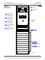
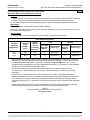
SYSTEM OVERVIEW
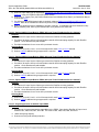
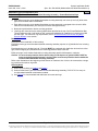
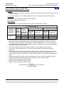
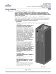
Description:
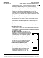
-48V DC @ up to 10,000 amperes power system.
This power system is designed to power a load while charging a positive grounded
battery. This power system is capable of operating in a batteryless installation or off
battery for maintenance purposes. This power system is designed for operation with the
positive output grounded.
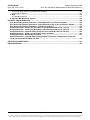
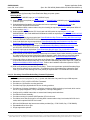
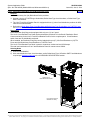
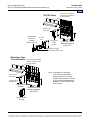
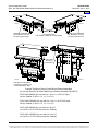
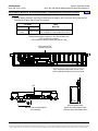
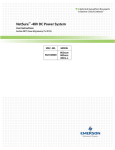
The NetSure™ 802NLDB (208V Input Power/Distribution and Power Only Bays), 802NLEB
(480V Input Power/Distribution and Power Only Bays), and 802NL-B (Distribution Only
Bay) DC Power System is a complete integrated power system containing rectifiers,
intelligent control, metering, monitoring, and distribution. This power system consists of
the following components.
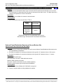
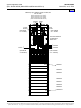
•
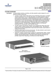
Power/Distribution Bays
The system can consist of one (1) Primary Power/Distribution Bay and up to nine (9)
Secondary Power/Distribution Bays.
Each Power/Distribution Bay can be equipped with up to ten (10) Rectifiers and
provides distribution. Distribution is divided into two buses which accept a choice of
fuse and circuit breaker types and sizes.
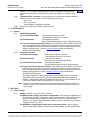
Each Power/Distribution Bay contains a Monitor and Control Panel. In the Primary
Power/Distribution Bay, this panel houses the Meter-Control-Alarm (MCA) assembly.
This panel in the Primary Power/Distribution Bay also houses the optional LMS Main
CPU circuit card of the integrated LMS Monitoring System. In a Secondary
Power/Distribution Bay, this panel can be equipped with an optional LMS Expansion
CPU circuit card. (The optional LMS
Monitoring System provides a higher
level of monitoring and controlling
capabilities to the power system.)
The Monitor and Control Panel in
both Primary and Secondary
Power/Distribution Bays contain a
seven-slot card cage to house MCA
alarm relay circuit cards, MCA
input/output (I/O) circuit cards, and
optional LMS I/O circuit cards. (If a
Secondary Power/Distribution Bay is
to be equipped with optional LMS I/O
circuit cards, it must also be
equipped with an LMS Expansion
CPU circuit card.)
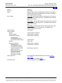
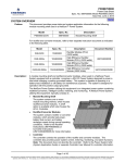
•
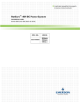
Power Only Bays
The system can consist of one (1)
Primary Power Only Bay and up to
nine (9) Secondary Power Only
Bays.
Each Power Only Bay can be
equipped with up to ten (10)
Rectifiers.
Each Power Only Bay contains
a Monitor and Control Panel. In
the Primary Power Only Bay,
this panel houses the Meter-
Primary
Power/Distribution Bay
Primary
Power Only Bay
Page 1 of 134
This document is property of Emerson Network Power, Energy Systems, North America, Inc. and contains confidential and proprietary information owned by Emerson Network Power, Energy
Systems, North America, Inc. Any copying, use, or disclosure of it without the written permission of Emerson Network Power, Energy Systems, North America, Inc. is strictly prohibited.
SAG582140000
Issue AW, June 3, 2014
System Application Guide
Spec. No. 582140000 (Models 802NLDB, 802NLEB and 802NL-B)
Home
Control-Alarm (MCA) assembly. This panel in the Primary Power Only Bay
also houses the optional LMS Main CPU circuit card of the integrated LMS
Monitoring System. In a Secondary Power Only Bay, this panel can be equipped
with an optional LMS Expansion CPU circuit card. (The optional LMS Monitoring
System provides a higher level of monitoring and controlling capabilities to the power
system.)
The Monitor and Control Panel in both Primary and Secondary Power Only Bays
contain a seven-slot card cage to house MCA alarm relay circuit cards, MCA
input/output (I/O) circuit cards, and optional LMS I/O circuit cards. (If a Secondary
Power Only Bay is to be equipped with optional LMS I/O circuit cards, it must also be
equipped with an LMS Expansion CPU circuit card.)
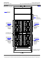
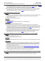
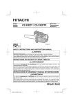
•
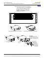
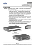
Distribution Only Bays
The system can consist of one (1) to eight (8) Distribution Only Bays.
Each Distribution Only Bay provides four (4) distribution buses.
Each distribution bus accepts a choice of 218-type circuit breakers and TPL-type
fuses.
A Distribution Only Bay may also be equipped with an optional distribution panel
which accepts a choice of TPS/TLS-type fuseholders or Bullet Nose-type circuit
breakers.
•
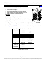
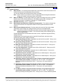
Rectifiers
The rectifiers provide load power, battery float current, and battery recharge current
during normal operating conditions.
•
MCA (Meter-Control-Alarm)
The MCA controls the operation of the rectifiers and provides power system control,
metering, monitoring, and alarm functions.
MCA Local Control Panel: This panel is located on the front of the Primary
Power/Distribution or Power Only Bay and contains a keypad, display, and indicators
for local MCA User interface.
MCA Relay Circuit Card: Each MCA relay circuit card
provides six (6) sets of Form-C relay contacts for customer
external alarms. These relays are User programmable for
various power system alarms. Up to sixteen (16) MCA
relay circuit cards can be installed in the Primary and
Secondary Power/Distribution and Power Only Bays. The
Primary Power/Distribution and Power Only Bays are
factory equipped with two (2) MCA relay circuit cards.
MCA I/O Circuit Cards: The MCA I/O circuit cards provide
analog inputs/outputs and binary inputs. Up to sixteen (16)
MCA I/O circuit cards can be installed in the Primary and
Secondary Power/Distribution and Power Only Bays.
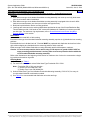
•
Optional Integrated LMS Monitoring System
The LMS Monitoring System consists of an LMS Main CPU
circuit card, optional LMS Expansion CPU circuit cards,
optional LMS I/O circuit cards, optional LMS Expansion
Cabinet, and optional LMS Expansion Assemblies.
The LMS Main CPU circuit card is mounted in the Primary
Power/Distribution and Power Only Bays. Each Secondary
Power/Distribution and Power Only Bay that is to be
equipped with optional LMS I/O circuit cards must
contain an LMS Expansion CPU circuit card. LMS
Distribution Only Bay
Page 2 of 134
This document is property of Emerson Network Power, Energy Systems, North America, Inc. and contains confidential and proprietary information owned by Emerson Network Power, Energy
Systems, North America, Inc. Any copying, use, or disclosure of it without the written permission of Emerson Network Power, Energy Systems, North America, Inc. is strictly prohibited.
System Application Guide
Spec. No. 582140000 (Models 802NLDB, 802NLEB and 802NL-B)
SAG582140000
Issue AW, June 3, 2014
Home
Expansion Cabinets and LMS Expansion Assemblies are available that
mount into customer equipment.
The LMS Monitoring System is factory integrated within each Power/Distribution,
Power Only, and Distribution Only Bay and requires no additional customer
interconnections within the bays. Simple cable connections between the
Power/Distribution, Power Only, and Distribution Only Bays complete the interbay
connections required. Separate analog, binary, and relay circuit cards do not have to
be supplied for power system monitoring. Analog, binary, relay, and temperature
circuit cards can be provided to monitor equipment external to the power system.
The LMS input circuit cards monitor a variety of analog, binary, and temperature
points external to the system. An LMS relay output circuit card is also available
which provides programmable relays. These relays may be used for external alarms,
or to control other equipment.
The LMS Monitoring System can be accessed via a local port, a modem port (when
optional modem is ordered), an optional TL1 port, and an Ethernet port (for Telnet
access, optional Web access, optional SNMP access, optional TL1 access, and
Email alarm reporting).
The LMS Monitoring System collects data from the power system and the input circuit
cards monitoring external points. The data collected is used for alarm processing
and reporting, and to provide statistics.
The LMS Monitoring System is capable of reporting alarm conditions to a remote
terminal, pager, Email address, via SNMP traps over Ethernet when the SNMP
option is ordered, or via TL1 (over Ethernet) when the 'TL1 over Ethernet' option is
ordered. TL1 is also available via a serial connection in 'direct mode'. For remote
terminal or pager notification, the LMS Main CPU circuit card must be equipped with
the optional modem. Two types of alarm reporting mechanisms are provided,
System Alarm Reporting and Individual User Alarm Reporting.
Refer to SAG586505000 for further LMS information. The SAG can be accessed via
the CD (Electronic Documentation Package) furnished with your system.
•
Applications
®
The NetSure™ 802NLDB and 802NLEB is capable of interfacing with Vortex Power
Systems (VPS).
The NetSure™ 802NLDB and 802NLEB is capable of interfacing with legacy power
systems.
Refer to the wiring diagrams in the Installation Instructions (Section 5876). Refer
also to Lists 64, 65, 66, and 67.
Page 3 of 134
This document is property of Emerson Network Power, Energy Systems, North America, Inc. and contains confidential and proprietary information owned by Emerson Network Power, Energy
Systems, North America, Inc. Any copying, use, or disclosure of it without the written permission of Emerson Network Power, Energy Systems, North America, Inc. is strictly prohibited.
SAG582140000
Issue AW, June 3, 2014
System Application Guide
Spec. No. 582140000 (Models 802NLDB, 802NLEB and 802NL-B)
Home
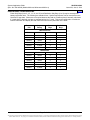
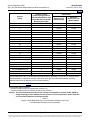
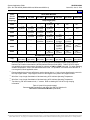
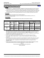
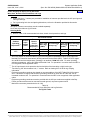
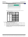
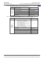
Family:
Spec. No.:
Model:
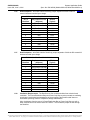
Input Voltage
Output Voltage:
Output Capacity:
System:
Power Only Bay:
Power/Distribution Bay:
Distribution Bus
(two Distribution Buses
per Power/Distribution Bay):
Rectifier:
Distribution Only Bay:
Distribution Bus:
(four Distribution Buses
per Distribution Only Bay)
Optional Distribution Panel:
(Bullet Nose Circuit
Breakers and/or TLS/TPS
Fuses) (one optional
Distribution Panel per
Distribution Only Bay)
Agency Approval:
Framework Type:
NetSure™
582140000
802NLDB (208V Input Power/Distribution and Power Only Bays)
802NLEB (480V Input Power/Distribution and Power Only Bays)
802NL-B (Distribution Only Bay)
R48-11600: Nominal 480 volts AC, three phase, 60 Hz, with an
operating range of 408 to 528 volts. Acceptable input frequency
range is 57 to 63 Hz.
or
R48-12000e: Nominal 480 volts AC, three phase, 60 Hz, with an
operating range of 340 to 528 volts. Acceptable input frequency
range is 57 to 63 Hz.
or
R48-12000Le: Nominal 208 volts AC, three phase, 60 Hz, with
an operating range of 176 to 264 volts. Acceptable input
frequency range is 47 to 63 Hz.
-48 Volts DC
10,000 Amperes, maximum
2200 Amperes, maximum
2400 Amperes, maximum
1200 Amperes
200A / -48V
6000 Amperes, maximum
1500 Amperes, maximum
500 Amperes, maximum
Power/Distribution Bay and Distribution Only Bay: Listed UL
1801, NEBS
Power Only Bay: UL 60950, NEBS
Seismic Rated (Zone 4) Box Framework
Page 4 of 134
This document is property of Emerson Network Power, Energy Systems, North America, Inc. and contains confidential and proprietary information owned by Emerson Network Power, Energy
Systems, North America, Inc. Any copying, use, or disclosure of it without the written permission of Emerson Network Power, Energy Systems, North America, Inc. is strictly prohibited.
System Application Guide
Spec. No. 582140000 (Models 802NLDB, 802NLEB and 802NL-B)
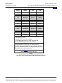
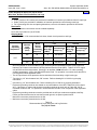
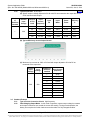
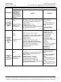
Power/Distribution Bay:
Width:
Depth:
Height:
Access:
Single Bay Plants:
Multi-Bay Plants:
Power Only Bay:
Width:
Depth:
Height:
Access:
Single Bay Plants:
Multi-Bay Plants:
Distribution Only Bay:
Width:
Depth:
Height:
Access:
SAG582140000
Issue AW, June 3, 2014
Home
24”, plus 10” if PDSC used
30”
93.5” Lists 1 and 11, 84” Lists 2 and 12
Front Access for Installation, Maintenance, and Operation.
Front and Rear Access for Installation and Maintenance, Front
for Operation.
24”
30”
84”
Front Access for Installation, Maintenance, and Operation.
Front and Rear Access for Installation and Maintenance, Front
for Operation.
Secondary Bay(s) Available:
Control:
Color:
31.375”
30”
84”
Front and Rear Access for Installation and Maintenance, Front
for Operation.
Nine
Microprocessor
Silver (Lorain Spec. M500-147)
Environment:
0°C to +40°C (+32°F to +104°F)
Page 5 of 134
This document is property of Emerson Network Power, Energy Systems, North America, Inc. and contains confidential and proprietary information owned by Emerson Network Power, Energy
Systems, North America, Inc. Any copying, use, or disclosure of it without the written permission of Emerson Network Power, Energy Systems, North America, Inc. is strictly prohibited.
SAG582140000
Issue AW, June 3, 2014
System Application Guide
Spec. No. 582140000 (Models 802NLDB, 802NLEB and 802NL-B)
Home
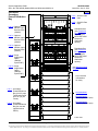
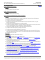
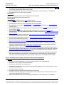
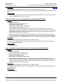
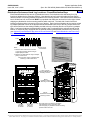
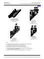
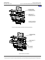
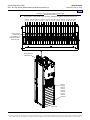
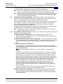
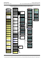
582140000
Primary
Power/Distribution
Bay
List A: 480VAC Plant
Input
List B: 208VAC Plant
Input
List 30: Optional
480VAC Input
Bolt-On PDSC
(22kAIC)
Distribution Bus
(see Distribution
Devices in
ACCESSORY
DESCRIPTIONS
Section for
distribution
options)
List 31: Optional
480VAC Input
Bolt-On PDSC
(65kAIC)
List 32: Optional
208VAC Input
Bolt-On PDSC
(65kAIC)
Distribution Bus
(see Distribution
Devices in
ACCESSORY
DESCRIPTIONS
Section for
distribution
options)
List 35: Surge
Suppression
Option
(480VAC
Input PDSC)
(see Monitor/Control
Diagram)
List 36: Surge
Suppression
Option
(208VAC
Input PDSC)
Door removed
in illustration
for clarity.
List 1: Primary
Power/Distribution
Bay (e/w AC Input
Termination Panel
with Ten [10] AC
Feeds)
P/N 486532602
or
P/N 486532603:
Rectifier (480VAC Input)
List 2: Primary
Power/Distribution
Bay (for use with
optional bolt-on
PDSC)
P/N 486534003:
Rectifier (208VAC Input)
Front View
Page 6 of 134
This document is property of Emerson Network Power, Energy Systems, North America, Inc. and contains confidential and proprietary information owned by Emerson Network Power, Energy
Systems, North America, Inc. Any copying, use, or disclosure of it without the written permission of Emerson Network Power, Energy Systems, North America, Inc. is strictly prohibited.
System Application Guide
Spec. No. 582140000 (Models 802NLDB, 802NLEB and 802NL-B)
SAG582140000
Issue AW, June 3, 2014
Home
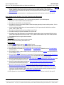
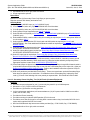
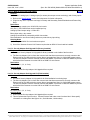
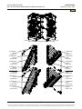
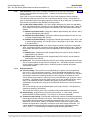
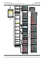
582140000
Secondary
Power/Distribution
Bay
List A: 480VAC Plant
Input
List B: 208VAC Plant
Input
List 30: Optional
480VAC Input
Bolt-On PDSC
(22kAIC)
Distribution Bus
(see Distribution
Devices in
ACCESSORY
DESCRIPTIONS
Section for
distribution
options)
List 31: Optional
480VAC Input
Bolt-On PDSC
(65kAIC)
List 32: Optional
208VAC Input
Bolt-On PDSC
(65kAIC)
Distribution Bus
(see Distribution
Devices in
ACCESSORY
DESCRIPTIONS
Section for
distribution
options)
List 35: Surge
Suppression
Option
(480VAC
Input PDSC)
List 36: Surge
Suppression
Option
(208VAC
Input PDSC)
(see Monitor/Control
Diagram)
Door removed
in illustration
for clarity.
List 11: Secondary
Power/Distribution
Bay (e/w AC Input
Termination Panel
with Ten [10] AC
Feeds)
P/N 486532602
or
P/N 486532603:
Rectifier (480VAC Input)
P/N 486534003:
Rectifier (208VAC Input)
List 12: Secondary
Power/Distribution
Bay (for use with
optional bolt-on
PDSC)
Front View
Page 7 of 134
This document is property of Emerson Network Power, Energy Systems, North America, Inc. and contains confidential and proprietary information owned by Emerson Network Power, Energy
Systems, North America, Inc. Any copying, use, or disclosure of it without the written permission of Emerson Network Power, Energy Systems, North America, Inc. is strictly prohibited.
SAG582140000
Issue AW, June 3, 2014
System Application Guide
Spec. No. 582140000 (Models 802NLDB, 802NLEB and 802NL-B)
Home
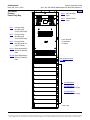
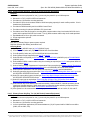
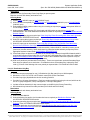
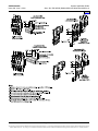
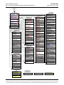
582140000
Primary
Power Only Bay
List A: 480VAC Plant
Input
List B: 208VAC Plant
Input
List 3: Primary Power
Only Bay (with
Five [5] AC Feeds)
List 4: Primary Power
Only Bay (with
Two [2] AC Feeds)
Door removed
in illustration
for clarity.
List 5: Primary Power
Only Bay (with Ten
[10] AC Feeds)
List 37: Surge Suppression
Option for 480VAC
Input
List 38: Surge Suppression
Option for 208VAC
Input
(see Monitor/Control
Diagram)
P/N 486532602
or
P/N 486532603:
Rectifier (480VAC Input)
P/N 486534003:
Rectifier (208VAC Input)
Front View
Page 8 of 134
This document is property of Emerson Network Power, Energy Systems, North America, Inc. and contains confidential and proprietary information owned by Emerson Network Power, Energy
Systems, North America, Inc. Any copying, use, or disclosure of it without the written permission of Emerson Network Power, Energy Systems, North America, Inc. is strictly prohibited.
System Application Guide
Spec. No. 582140000 (Models 802NLDB, 802NLEB and 802NL-B)
SAG582140000
Issue AW, June 3, 2014
Home
582140000
Secondary
Power Only Bay
List A: 480VAC Plant
Input
List B: 208VAC Plant
Input
List 13: Secondary Power
Only Bay (with
Five [5] AC Feeds)
List 14: Secondary Power
Only Bay (with
Two [2] AC Feeds)
Door removed
in illustration
for clarity.
List 15: Secondary Power
Only Bay (with Ten
[10] AC Feeds)
List 37: Surge Suppression
Option for 480VAC
Input
List 38: Surge Suppression
Option for 208VAC
Input
(see Monitor/Control
Diagram)
P/N 486532602
or
P/N 486532603:
Rectifier (480VAC Input)
P/N 486534003:
Rectifier (208VAC Input)
Front View
Page 9 of 134
This document is property of Emerson Network Power, Energy Systems, North America, Inc. and contains confidential and proprietary information owned by Emerson Network Power, Energy
Systems, North America, Inc. Any copying, use, or disclosure of it without the written permission of Emerson Network Power, Energy Systems, North America, Inc. is strictly prohibited.
SAG582140000
Issue AW, June 3, 2014
System Application Guide
Spec. No. 582140000 (Models 802NLDB, 802NLEB and 802NL-B)
Home
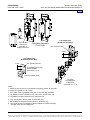
582140000
Distribution Only Bay
List 16: Distribution
Only Bay
Blank Panel
or
List C: Bullet
Fuse/Circuit
Breaker Panel
Distribution Bus
(see Distribution
Devices in
ACCESSORY
DESCRIPTIONS
Section for
distribution
options)
Distribution Bus
(see Distribution
Devices in
ACCESSORY
DESCRIPTIONS
Section for
distribution
options)
(see Monitor and
Control Diagram)
Distribution Bus
(see Distribution
Devices in
ACCESSORY
DESCRIPTIONS
Section for
distribution
options)
Distribution Bus
(see Distribution
Devices in
ACCESSORY
DESCRIPTIONS
Section for
distribution
options)
Front door removed in
illustration for clarity.
Front View
Page 10 of 134
This document is property of Emerson Network Power, Energy Systems, North America, Inc. and contains confidential and proprietary information owned by Emerson Network Power, Energy
Systems, North America, Inc. Any copying, use, or disclosure of it without the written permission of Emerson Network Power, Energy Systems, North America, Inc. is strictly prohibited.
SAG582140000
Issue AW, June 3, 2014
System Application Guide
Spec. No. 582140000 (Models 802NLDB, 802NLEB and 802NL-B)
Home
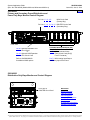
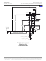
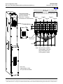
582140000
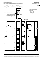
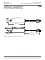
Primary and Secondary Power/Distribution and
Power Only Bays Monitor/Control Diagram
P/O List 1, 2, 3, 4, 5:
MCA Circuit Card
(Primary Bay)
P/O List 11, 12, 13, 14, 15: ROUTER Circuit Card
(Secondary Bay)
Front View
List 50: Optional LMS Main CPU
Circuit Card
or
List 63: Optional LMS Expansion
CPU Circuit Card
Available MCA Input/Output (I/O)
Circuit Cards
List 70: MCA Customer Alarm
Relay Circuit Card (Six [6]
Form-C Contacts)
Refer to SAG586505000
for additional LMS options.
List 71: MCA Analog Input/Output
and Binary Input Circuit Card
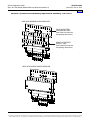
582140000
Distribution Only Bays Monitor and Control Diagram
P/O Lists 16:
ROUTER Circuit Card
SEE ALSO
System Overview
Table of Contents
List Descriptions
Accessory Descriptions
Specifications
Physical Size Information
Related Documentation
Page 11 of 134
This document is property of Emerson Network Power, Energy Systems, North America, Inc. and contains confidential and proprietary information owned by Emerson Network Power, Energy
Systems, North America, Inc. Any copying, use, or disclosure of it without the written permission of Emerson Network Power, Energy Systems, North America, Inc. is strictly prohibited.
SAG582140000
Issue AW, June 3, 2014
System Application Guide
Spec. No. 582140000 (Models 802NLDB, 802NLEB and 802NL-B)
TABLE OF CONTENTS
System
Overview
Picture
List
Descriptions
Accessory
Descriptions
Specifications
Physical Size
Information
Related
Documentation
SYSTEM OVERVIEW................................................................................................................................................. 1
582140000 Primary Power/Distribution Bay ..................................................................................................... 6
582140000 Secondary Power/Distribution Bay ................................................................................................ 7
582140000 Primary Power Only Bay ................................................................................................................. 8
582140000 Secondary Power Only Bay ............................................................................................................ 9
582140000 Distribution Only Bay..................................................................................................................... 10
582140000 Primary and Secondary Power/Distribution and Power Only Bays Monitor/Control
Diagram .............................................................................................................................................................. 11
582140000 Distribution Only Bays Monitor and Control Diagram ............................................................... 11
TABLE OF CONTENTS ........................................................................................................................................... 12
LIST DESCRIPTIONS .............................................................................................................................................. 15
List A: 480VAC Plant Input Voltage .............................................................................................................. 15
List B: 208VAC Plant Input Voltage .............................................................................................................. 15
List 1: Primary Power/Distribution Bay (Common Equipment) ..................................................................... 15
List 2: Primary Power/Distribution Bay (Common Equipment) ..................................................................... 16
List 3: Primary Power Only Bay, Five (5) AC Feeds (Common Equipment)................................................. 17
List 4: Primary Power Only Bay, Two (2) AC Feeds (Common Equipment)................................................. 18
List 5: Primary Power Only Bay, Ten (10) AC Feeds (Common Equipment) ............................................... 18
List 11: Secondary Power/Distribution Bay (Common Equipment) .............................................................. 19
List 12: Secondary Power/Distribution Bay (Common Equipment) .............................................................. 20
List 13: Secondary Power Only Bay, Five (5) AC Feeds (Common Equipment) .......................................... 21
List 14: Secondary Power Only Bay, Two (2) AC Feeds (Common Equipment) .......................................... 22
List 15: Secondary Power Only Bay, Ten (10) AC Feeds (Common Equipment) ........................................ 23
List 16: Distribution Only Bay ........................................................................................................................ 24
List 30: Optional 480VAC Input Bolt-On PDSC (AC Input 'Power Distribution Service Cabinet') ................ 25
List 31: Optional 480VAC Input Bolt-On PDSC (AC Input 'Power Distribution Service Cabinet') ................ 25
List 32: Optional 208VAC Input Bolt-On PDSC (AC Input 'Power Distribution Service Cabinet') ................ 25
List 35: Surge Suppression for 480VAC Input PDSC ................................................................................... 25
List 36: Surge Suppression for 208VAC Input PDSC ................................................................................... 26
List 37: Surge Suppression for 208VAC Input .............................................................................................. 26
List 38: Surge Suppression for 480VAC Input .............................................................................................. 27
List 50: Optional LMS Main CPU Circuit Card (Primary Power/Distribution and Power Only Bays) ............ 27
List 63: Optional LMS Expansion CPU Circuit Card (Secondary Power/Distribution and Power Only
Bays) .............................................................................................................................................................. 27
List 64: Interface Kit to a Spec. No. 582121900 Power System equipped with a DGU................................ 28
List 65: Interface Kit to a Spec. No. 582121901 Power System equipped with an LMS1000 ...................... 28
List 66: Interface Kit to a Vortex Power System without a DGU or LMS1000 .............................................. 29
List 67: Interface Kit to a Model 1231H Legacy Power System with 1-8 Rectifiers ...................................... 29
List 70: Additional MCA Six (6) Output Form-C Relay Circuit Card .............................................................. 29
List 71: MCA I/O Circuit Card P/N 524550 .................................................................................................... 30
List 73: Security Adapter Unit Upgrade Kit (Factory Installed) ..................................................................... 30
List 74: Security Adapter Unit Upgrade Kit (Field Installed) .......................................................................... 30
List C: 24 Position Bullet-Nose Circuit Breaker/Fuse Panel ......................................................................... 31
ACCESSORY DESCRIPTIONS ............................................................................................................................... 32
Rectifiers ............................................................................................................................................................ 32
P/N 486532602, Rectifier (480VAC Input) ..................................................................................................... 32
P/N 486532603, Rectifier (480VAC Input) ..................................................................................................... 32
Page 12 of 134
This document is property of Emerson Network Power, Energy Systems, North America, Inc. and contains confidential and proprietary information owned by Emerson Network Power, Energy
Systems, North America, Inc. Any copying, use, or disclosure of it without the written permission of Emerson Network Power, Energy Systems, North America, Inc. is strictly prohibited.
System Application Guide
Spec. No. 582140000 (Models 802NLDB, 802NLEB and 802NL-B)
SAG582140000
Issue AW, June 3, 2014
P/N 486534003, Rectifier (208VAC Input) ..................................................................................................... 32
External Main Termination Bars ...................................................................................................................... 33
Distribution Devices and Load Lug Locations - Power/Distribution Bays .................................................. 34
Distribution Device and Load Lug Locations – Distribution Only Bays ...................................................... 36
Distribution Devices .......................................................................................................................................... 39
218 Circuit Breaker Assemblies ..................................................................................................................... 39
TPL Fuses and Fuseholder Assemblies ......................................................................................................... 43
Bullet Nose-Type Circuit Breakers and Bullet Nose-Type Circuit Breaker/Fuseholder Mounting
Assembly – Power/Distribution Bays ............................................................................................................. 46
TLS/TPS Fuses, Bullet Nose-Type Fuseholders, and Bullet Nose-Type Circuit Breaker/Fuseholder
Mounting Assembly – Power/Distribution Bays ............................................................................................. 49
Bullet Nose-Type Circuit Breakers and Bullet Nose-Type Fuseholders e/w TLS/TPS Fuses –
Distribution Only Bays .................................................................................................................................... 52
Optional Bullet Nose-Type 10-Position GMT Fuse Module for List C............................................................ 54
Replacement Alarm, Reference, and Control Fuses...................................................................................... 55
Fuseblock Located in Bay’s Left Center ........................................................................................................ 55
Input and Alarm Fuse on Optional Bullet Nose-Type 10-Position GMT Fuse Module, P/N 509128 ............. 57
Optional Power/Distribution Bay Internal Ground Busbar Kits .................................................................... 57
Optional Internal Ground Busbar Kit (P/N 554862)........................................................................................ 57
Optional Internal Ground Busbar Kit (P/N 555214)........................................................................................ 58
Power/Distribution and Power Only Bays External Busbars ........................................................................ 60
Optional External Top-Mount Horizontal Battery Input Busbar Assembly ..................................................... 60
Optional Busbar Shield Kit ............................................................................................................................. 60
Optional External Top-Mount Ground (Load Return) Busbar Assemblies ..................................................... 60
Optional Load Return Lug Extension Busbar Assembly ................................................................................ 61
Optional External Top-Mount Vertical Battery Input Busbar Assembly ......................................................... 68
Wiring Components .......................................................................................................................................... 72
Power/Distribution and Power Only Bays Frame Grounding Wire Sizes and Lugs....................................... 72
Distribution Only Bay Frame Grounding Wire Sizes and Lugs Selection ...................................................... 73
Power/Distribution Bay and Distribution Only Bay Load Distribution Wire Sizes and Lugs........................... 74
Power/Distribution Bay Battery Cable Sizes and Lugs .................................................................................. 78
Power Only Bay DC Output Cable Sizes and Lugs ....................................................................................... 80
Distribution Only Bay DC Input Cable Sizes and Lugs Selection .................................................................. 82
Power/Distribution Bay AC Input, Ten (10) AC Feeds Wire Sizes, Branch Circuit Protection, and Lugs...... 84
Power/Distribution Bay AC Input, Two (2) AC Feeds Wire Sizes, Branch Circuit Protection, and Lugs ....... 86
Power/Distribution Bay AC Input, One (1) AC Feed Wire Sizes, Branch Circuit Protection, and Lugs ......... 88
Power Only Bay AC Input, Five (5) AC Feeds Wire Sizes, Branch Circuit Protection, and Lugs .................. 90
Power Only Bay AC Input, Two (2) AC Feeds Wire Sizes, Branch Circuit Protection, and Lugs .................. 92
Power Only Bay AC Input, Ten (10) AC Feeds Wire Sizes, Branch Circuit Protection, and Lugs ................ 94
External Alarm, Reference, and Control Wire Sizes - Power/Distribution and Power Only Bays.................. 96
Optional Battery Charge Temperature Compensation Probe for Digital Compensation........................... 97
Replacement/Additional MCA Network Cable ................................................................................................ 98
Replacement/Additional LMS Network Cable................................................................................................. 98
Replacement Circuit Cards .............................................................................................................................. 98
SPECIFICATIONS.................................................................................................................................................... 99
1. System ........................................................................................................................................................... 99
1.2 Environmental Ratings ............................................................................................................................. 99
1.3 Compliance Information ......................................................................................................................... 101
1.4 Local Controls and Indicators ................................................................................................................. 101
2. DC Distribution............................................................................................................................................ 102
2.1 Ratings ................................................................................................................................................... 102
3. Rectifier ........................................................................................................................................................ 102
3.1 Output Ratings ....................................................................................................................................... 102
3.2 Input Ratings (480VAC, with 486532602 Rectifier) ............................................................................... 103
3.3 Input Ratings (480VAC, with 486532603 Rectifier) ............................................................................... 105
Page 13 of 134
This document is property of Emerson Network Power, Energy Systems, North America, Inc. and contains confidential and proprietary information owned by Emerson Network Power, Energy
Systems, North America, Inc. Any copying, use, or disclosure of it without the written permission of Emerson Network Power, Energy Systems, North America, Inc. is strictly prohibited.
SAG582140000
Issue AW, June 3, 2014
System Application Guide
Spec. No. 582140000 (Models 802NLDB, 802NLEB and 802NL-B)
3.4 Input Ratings (208VAC, with 486534003 Rectifier) ............................................................................... 106
3.5 Standard Features.................................................................................................................................. 107
4. MCA .............................................................................................................................................................. 112
4.1 Standard Features.................................................................................................................................. 112
5. Optional LMS Monitoring System ............................................................................................................. 123
PHYSICAL SIZE INFORMATION .......................................................................................................................... 124
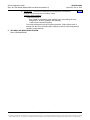
Floor Hole Drilling Pattern Dimensions - Power/Distribution and Power Only Bays ............................... 124
Floor Hole Drilling Pattern Dimensions - Power/Distribution Bay w/ AC Input Service Cabinet ............ 125
Floor Hole Drilling Pattern Dimensions - Distribution Only Bay ................................................................ 126
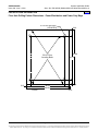
Overall Dimensions - Primary and Secondary Power/Distribution Bays (List 1 and 11) ......................... 127
Overall Dimensions - Primary and Secondary Power/Distribution Bays (List 2 and 12) ......................... 128
Overall Dimensions – Optional PDSC (AC Input ‘Power Distribution Service Cabinet’) ......................... 129
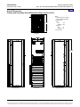
Overall Dimensions - Primary and Secondary Power Only Bays ............................................................... 130
Overall Dimensions –Distribution Only Bays ............................................................................................... 131
Overall Dimensions – Optional Battery Charge Digital Temperature Compensation Probes P/N
107021 (25 feet) and P/N 106824 (100 feet) ................................................................................................... 132
RELATED DOCUMENTATION.............................................................................................................................. 133
REVISION RECORD .............................................................................................................................................. 134
Page 14 of 134
This document is property of Emerson Network Power, Energy Systems, North America, Inc. and contains confidential and proprietary information owned by Emerson Network Power, Energy
Systems, North America, Inc. Any copying, use, or disclosure of it without the written permission of Emerson Network Power, Energy Systems, North America, Inc. is strictly prohibited.
System Application Guide
Spec. No. 582140000 (Models 802NLDB, 802NLEB and 802NL-B)
SAG582140000
Issue AW, June 3, 2014
Home
LIST DESCRIPTIONS
List A: 480VAC Plant Input Voltage
Features
♦
Specifies 480VAC Plant Input Voltage.
List B: 208VAC Plant Input Voltage
Features
♦
Specifies 208VAC Plant Input Voltage.
List 1: Primary Power/Distribution Bay (Common Equipment)
Features
♦
Provides common equipment for one (1) “power and distribution” bay rated for up to 2400 amperes.
♦
Mounted in a 93.5"H x 24"W x 30"D box framework.
♦
Provides ten (10) Rectifier mounting positions.
♦
Provides an AC input termination panel that accepts ten (10) AC input branch circuits, one (1) per
Rectifier mounting position.
♦
Provides forty-eight (48) distribution device mounting positions.
♦
Provides two (2) buses of distribution. Each bus contains an MCA monitoring circuit card; which can be
set for no group designation, Group A designation, or Group B designation.
♦
Configured for a 4000A internal bus or external main battery termination bars.
♦
Provides the MCA Assembly and Local MCA Control Panel.
♦
Provides mounting for optional LMS Main CPU circuit card.
♦
Provides a seven-slot card cage for mounting MCA customer alarm relay circuit cards, MCA I/O circuit
cards, and/or optional LMS I/O circuit cards. Two (2) MCA customer alarm relay circuit cards provided.
♦ Expandable either left or right.
Restrictions
Only one (1) Primary Bay per power system required.
Ordering Notes
1) Specify List A (480VAC Input) or List B (208VAC Input).
2) Order Rectifiers as required per P/N 486532602 or P/N 486532603 (480VAC Input) or P/N 486534003
(208VAC Input).
3) Order distribution fuse and/or circuit breaker devices as required per Distribution Devices in the
ACCESSORY DESCRIPTIONS section.
4) Order additional MCA customer alarm relay circuit card(s) as required per List 70, and optional MCA I/O
circuit cards per List 71.
5) Order a Battery Charge Temperature Compensation Probe as required per Battery Charge Temperature
Compensation Probe for Digital Compensation in the ACCESSORY DESCRIPTIONS section.
6) Order optional LMS Monitor and LMS options as required per List 50, and SAG586505000.
7) Order bay grounding lugs as required per Power/Distribution Bay Frame Grounding Wire Sizes and Lugs
in the ACCESSORY DESCRIPTIONS section.
8) Order load distribution lugs as required per Power/Distribution Bay and Distribution Only Bay Load
Distribution Wire Sizes and Lugs in the ACCESSORY DESCRIPTIONS section.
9) Order battery cable lugs as required per Power/Distribution Bay Battery Cable Sizes and Lugs in the
ACCESSORY DESCRIPTIONS section.
10) Order AC input lugs as required per Power/Distribution Bay AC Input, Ten (10) Rectifier Feeds Wire
Sizes, Branch Circuit Protection, and Lugs in the ACCESSORY DESCRIPTIONS section.
Page 15 of 134
This document is property of Emerson Network Power, Energy Systems, North America, Inc. and contains confidential and proprietary information owned by Emerson Network Power, Energy
Systems, North America, Inc. Any copying, use, or disclosure of it without the written permission of Emerson Network Power, Energy Systems, North America, Inc. is strictly prohibited.
SAG582140000
Issue AW, June 3, 2014
System Application Guide
Spec. No. 582140000 (Models 802NLDB, 802NLEB and 802NL-B)
Home
11) Order internal ground busbar assembly, external top-mount battery input busbar assembly,
busbar shield kit, external top-mount ground (load return) busbar assembly, and/or load return
lug extension busbar assembly as required per the appropriate sections located under ACCESSORY
DESCRIPTIONS.
12) If the system is to be connected to an existing system with an MCA, refer to List 64, 65, 66, and 67.
List 2: Primary Power/Distribution Bay (Common Equipment)
Features
♦
Provides common equipment for one (1) “power and distribution” bay rated for up to 2400 amperes.
♦
Mounted in a 7'0"H x 24"W x 30"D Box Framework.
♦
Provides ten (10) Rectifier mounting positions.
♦
Provides forty-eight (48) distribution device mounting positions.
♦
Provides two (2) buses of distribution. Each bus contains an MCA monitoring circuit card; which can be
set for no group designation, Group A designation, or Group B designation.
♦
Configured for a 4000A internal bus or external main battery termination bars.
♦
Provides the MCA Assembly and Local MCA Control Panel.
♦
Provides mounting for optional LMS Main CPU circuit card.
♦
Provides a seven-slot card cage for mounting MCA customer alarm relay circuit cards, MCA I/O circuit
cards, and/or optional LMS I/O circuit cards. Two (2) MCA customer alarm relay circuit cards provided.
♦
Expandable either left or right.
♦ Surge suppression optional.
Restrictions
Only one (1) Primary Bay per power system required.
Requires List 30 (480VAC Input), List 31 (480VAC Input), or List 32 (208VAC Input) Bolt-On PDSC (AC Input
'Power Distribution Service Cabinet').
Ordering Notes
1) Specify List A (480VAC Input) or List B (208VAC Input).
2) Order Bolt-On PDSC (AC Input 'Power Distribution Service Cabinet') per List 30 (480VAC Input), List 31
(480VAC Input), or List 32 (208VAC Input).
3) Order Rectifiers as required per P/N 486532602 or P/N 486532603 (480VAC Input) or P/N 486534003
(208VAC Input).
4) Order distribution fuse and/or circuit breaker devices as required per Distribution Devices in the
ACCESSORY DESCRIPTIONS section.
5) Order additional MCA customer alarm relay circuit card(s) as required per List 70, and optional MCA I/O
circuit cards per List 71.
6) Order a Battery Charge Temperature Compensation Probe as required per Battery Charge Temperature
Compensation Probe for Digital Compensation in the ACCESSORY DESCRIPTIONS section.
7) Order optional LMS Monitor and LMS options as required per List 50, and SAG586505000.
8) Order bay grounding lugs as required per Power/Distribution Bay Frame Grounding Wire Sizes and Lugs
in the ACCESSORY DESCRIPTIONS section.
9) Order load distribution lugs as required per Power/Distribution Bay and Distribution Only Bay Load
Distribution Wire Sizes and Lugs in the ACCESSORY DESCRIPTIONS section.
10) Order battery cable lugs as required per Power/Distribution Bay Battery Cable Sizes and Lugs in the
ACCESSORY DESCRIPTIONS section.
11) Order AC input lugs as required per Power/Distribution Bay AC Input, Two (2) Rectifier Feeds Wire Sizes,
Branch Circuit Protection, and Lugs or Power/Distribution Bay AC Input, One (1) Rectifier Feed Wire
Sizes, Branch Circuit Protection, and Lugs in the ACCESSORY DESCRIPTIONS section.
Page 16 of 134
This document is property of Emerson Network Power, Energy Systems, North America, Inc. and contains confidential and proprietary information owned by Emerson Network Power, Energy
Systems, North America, Inc. Any copying, use, or disclosure of it without the written permission of Emerson Network Power, Energy Systems, North America, Inc. is strictly prohibited.
System Application Guide
Spec. No. 582140000 (Models 802NLDB, 802NLEB and 802NL-B)
SAG582140000
Issue AW, June 3, 2014
Home
12) Order internal ground busbar assembly, external top-mount battery input busbar assembly,
busbar shield kit, external top-mount ground (load return) busbar assembly, and/or load return
lug extension busbar assembly as required per the appropriate sections located under ACCESSORY
DESCRIPTIONS.
13) If the system is to be connected to an existing system with an MCA, refer to List 64, 65, 66, and 67.
List 3: Primary Power Only Bay, Five (5) AC Feeds (Common Equipment)
Features
♦
Provides common equipment for one (1) power only bay rated for up to 2200 amperes.
♦
Mounted in a 7’0”H x 24"W x 30"D box framework.
♦
Provides ten (10) Rectifier mounting positions.
♦
Provides AC input circuit breakers rated for 22kA interrupting capacity for each rectifier position. Circuit
breakers are pad-lockable.
♦
In ferro replacement applications, will accommodate five (5) AC inputs sized for 400A ferro rectifiers
(208V, 100A or 480V, 50A).
♦
Provides the MCA Assembly and Local MCA Control Panel.
♦
Provides mounting for optional LMS Main CPU circuit card.
♦
Provides a seven-slot card cage for mounting MCA customer alarm relay circuit cards, MCA I/O circuit
cards, and/or optional LMS I/O circuit cards. Two (2) MCA customer alarm relay circuit cards provided.
♦ Expandable either left or right, cable connected.
Restrictions
Only one (1) Primary Bay per power system required.
Requires external main battery termination bars.
Ordering Notes
1) Specify List A (480VAC Input) or List B (208VAC Input).
2) If List A specified, order ten (10) P/N 256933200 30A circuit breakers.
3) If List B specified, order ten (10) P/N 256937200 60A circuit breakers.
4) Order Rectifiers as required per P/N 486532602 or P/N 486532603 (480VAC Input) or P/N 486534003
(208VAC Input).
5) Order additional MCA customer alarm relay circuit card(s) as required per List 70, and optional MCA I/O
circuit cards per List 71.
6) Order a Battery Charge Temperature Compensation Probe as required per Battery Charge Temperature
Compensation Probe for Digital Compensation in the ACCESSORY DESCRIPTIONS section.
7) Order optional LMS Monitor and LMS options as required per List 50, and SAG586505000.
8) Order bay grounding lugs as required per Power Only Bay Frame Grounding Wire Sizes and Lugs in the
ACCESSORY DESCRIPTIONS section.
9) Order DC output cable lugs as required per Power Only Bay DC Output Cable Sizes and Lugs in the
ACCESSORY DESCRIPTIONS section.
10) Order AC input lugs as required per Power Only Bay AC Input, Five (5) Rectifier Feeds Wire Sizes,
Branch Circuit Protection, and Lugs in the ACCESSORY DESCRIPTIONS section.
11) Order external top-mount battery input busbar assembly, busbar shield kit, external top-mount ground
(load return) busbar assembly, and/or load return lug extension busbar assembly as required per the
appropriate sections located under ACCESSORY DESCRIPTIONS.
12) If the system is to be connected to an existing system with an MCA, refer to List 64, 65, 66, and 67.
Page 17 of 134
This document is property of Emerson Network Power, Energy Systems, North America, Inc. and contains confidential and proprietary information owned by Emerson Network Power, Energy
Systems, North America, Inc. Any copying, use, or disclosure of it without the written permission of Emerson Network Power, Energy Systems, North America, Inc. is strictly prohibited.
SAG582140000
Issue AW, June 3, 2014
System Application Guide
Spec. No. 582140000 (Models 802NLDB, 802NLEB and 802NL-B)
List 4: Primary Power Only Bay, Two (2) AC Feeds (Common Equipment)
Features
Home
♦
Provides common equipment for one (1) power only bay rated for up to 2200 amperes.
♦
Mounted in a 7’0”H x 24"W x 30"D box framework.
♦
Provides ten (10) Rectifier mounting positions.
♦
Provides AC input circuit breakers rated for 22kA interrupting capacity for each rectifier position. Circuit
breakers are pad-lockable.
♦
Provides the MCA Assembly and Local MCA Control Panel.
♦
Provides mounting for optional LMS Main CPU circuit card.
♦
Provides a seven-slot card cage for mounting MCA customer alarm relay circuit cards, MCA I/O circuit
cards, and/or optional LMS I/O circuit cards. Two (2) MCA customer alarm relay circuit cards provided.
♦
Expandable either left or right, cable connected.
♦ Surge suppression optional.
Restrictions
Only one (1) Primary Bay per power system required.
Requires external main battery termination bars.
Ordering Notes
1) Specify List A (480VAC Input) or List B (208VAC Input).
2) If List A specified, order ten (10) P/N 256933200 30A circuit breakers.
3) If List B specified, order ten (10) P/N 256937200 60A circuit breakers.
4) Order Optional Surge Suppressors per List 37 or List 38.
5) Order Rectifiers as required per P/N 486532602 or P/N 486532603 (480VAC Input) or P/N 486534003
(208VAC Input).
6) Order additional MCA customer alarm relay circuit card(s) as required per List 70, and optional MCA I/O
circuit cards per List 71.
7) Order a Battery Charge Temperature Compensation Probe as required per Battery Charge Temperature
Compensation Probe for Digital Compensation in the ACCESSORY DESCRIPTIONS section.
8) Order optional LMS Monitor and LMS options as required per List 50, and SAG586505000.
9) Order bay grounding lugs as required per Power Only Bay Frame Grounding Wire Sizes and Lugs in the
ACCESSORY DESCRIPTIONS section.
10) Order DC output cable lugs as required per Power Only Bay DC Output Cable Sizes and Lugs in the
ACCESSORY DESCRIPTIONS section.
11) Order AC input lugs as required per Power Only Bay AC Input, Two (2) Rectifier Feeds Wire Sizes,
Branch Circuit Protection, and Lugs in the ACCESSORY DESCRIPTIONS section.
12) Order external top-mount battery input busbar assembly, busbar shield kit, external top-mount ground
(load return) busbar assembly, and/or load return lug extension busbar assembly as required per the
appropriate sections located under ACCESSORY DESCRIPTIONS.
13) If the system is to be connected to an existing system with an MCA, refer to List 64, 65, 66, and 67.
List 5: Primary Power Only Bay, Ten (10) AC Feeds (Common Equipment)
Features
♦
Provides common equipment for one (1) power only bay rated for up to 2200 amperes.
♦
Mounted in a 7’0”H x 24"W x 30"D box framework.
♦
Provides ten (10) Rectifier mounting positions.
♦
In ferro replacement applications, will accommodate ten (10) AC inputs sized for 200A ferro rectifiers
(208V, 60A or 480V, 25A).
Page 18 of 134
This document is property of Emerson Network Power, Energy Systems, North America, Inc. and contains confidential and proprietary information owned by Emerson Network Power, Energy
Systems, North America, Inc. Any copying, use, or disclosure of it without the written permission of Emerson Network Power, Energy Systems, North America, Inc. is strictly prohibited.
System Application Guide
Spec. No. 582140000 (Models 802NLDB, 802NLEB and 802NL-B)
SAG582140000
Issue AW, June 3, 2014
Home
♦
Provides the MCA Assembly and Local MCA Control Panel.
♦
Provides mounting for optional LMS Main CPU circuit card.
♦
Provides a seven-slot card cage for mounting MCA customer alarm relay circuit cards, MCA I/O circuit
cards, and/or optional LMS I/O circuit cards. Two (2) MCA customer alarm relay circuit cards provided.
♦ Expandable either left or right, cable connected.
Restrictions
Only one (1) Primary Bay per power system required.
Requires external main battery termination bars.
Ordering Notes
1) Specify List A (480VAC Input) or List B (208VAC Input).
2) Order Rectifiers as required per P/N 486532602 or P/N 486532603 (480VAC Input) or P/N 486534003
(208VAC Input).
3) Order additional MCA customer alarm relay circuit card(s) as required per List 70, and optional MCA I/O
circuit cards per List 71.
4) Order a Battery Charge Temperature Compensation Probe as required per Battery Charge Temperature
Compensation Probe for Digital Compensation in the ACCESSORY DESCRIPTIONS section.
5) Order optional LMS Monitor and LMS options as required per List 50, and SAG586505000.
6) Order bay grounding lugs as required per Power Only Bay Frame Grounding Wire Sizes and Lugs in the
ACCESSORY DESCRIPTIONS section.
7) Order DC output cable lugs as required per Power Only Bay DC Output Cable Sizes and Lugs in the
ACCESSORY DESCRIPTIONS section.
8) Order AC input lugs as required per Power Only Bay AC Input, Ten (10) Rectifier Feed Wire Sizes,
Branch Circuit Protection, and Lugs in the ACCESSORY DESCRIPTIONS section.
9) Order external top-mount battery input busbar assembly, busbar shield kit, external top-mount ground
(load return) busbar assembly, and/or load return lug extension busbar assembly as required per the
appropriate sections located under ACCESSORY DESCRIPTIONS.
10) If the system is to be connected to an existing system with an MCA, refer to List 64, 65, 66, and 67.
List 11: Secondary Power/Distribution Bay (Common Equipment)
Features
♦
Provides common equipment for one (1) “power and distribution” bay rated for up to 2400 amperes.
♦
Mounted in a 93.5"H x 24"W x 30"D Box Framework.
♦
Provides ten (10) Rectifier mounting positions.
♦
Provides an AC input termination panel that accepts ten (10) AC input branch circuits, one (1) per
Rectifier mounting position.
♦
Provides forty-eight (48) distribution device mounting positions.
♦
Provides two (2) buses of distribution. Each bus contains an MCA monitoring circuit card; which can be
set for no group designation, Group A designation, or Group B designation.
♦
Configured for a 4000A internal bus or external main battery termination bars.
♦
Provides the Router Assembly.
♦
Provides mounting for optional LMS Expansion CPU circuit card.
♦
Provides a seven-slot card cage for mounting MCA customer alarm relay circuit cards, MCA I/O circuit
cards, and/or optional LMS I/O circuit cards.
♦
MCA and LMS Network bay interconnect cables provided (Qty. 1 P/N 514642, Qty. 1 P/N 514639).
♦
Expandable either left or right.
Page 19 of 134
This document is property of Emerson Network Power, Energy Systems, North America, Inc. and contains confidential and proprietary information owned by Emerson Network Power, Energy
Systems, North America, Inc. Any copying, use, or disclosure of it without the written permission of Emerson Network Power, Energy Systems, North America, Inc. is strictly prohibited.
SAG582140000
Issue AW, June 3, 2014
System Application Guide
Spec. No. 582140000 (Models 802NLDB, 802NLEB and 802NL-B)
Home
Restrictions
Maximum of nine (9) Secondary Power/Distribution Bays per power system.
Ordering Notes
1) Specify List A (480VAC Input) or List B (208VAC Input).
2) Order Rectifiers as required per P/N 486532602 or P/N 486532603 (480VAC Input) or P/N 486534003
(208VAC Input).
3) Order distribution fuse and/or circuit breaker devices as required per Distribution Devices in the
ACCESSORY DESCRIPTIONS section.
4) Order additional MCA customer alarm relay circuit card(s) as required per List 70, and optional MCA I/O
circuit cards per List 71.
5) Order optional LMS Expansion CPU circuit card and LMS options as required per List 63, and
SAG586505000. Also order additional LMS Network cables as required per Replacement/Additional LMS
Network Cables.
6) Order bay grounding lugs as required per Power/Distribution Bay Frame Grounding Wire Sizes and Lugs
in the ACCESSORY DESCRIPTIONS section.
7) Order load distribution lugs as required per Power/Distribution Bay and Distribution Only Bay Load
Distribution Wire Sizes and Lugs in the ACCESSORY DESCRIPTIONS section.
8) Order battery cable lugs as required per Power/Distribution Bay Battery Cable Sizes and Lugs in the
ACCESSORY DESCRIPTIONS section.
9) Order AC input lugs as required per Power/Distribution Bay AC Input, Ten (10) Rectifier Feeds Wire
Sizes, Branch Circuit Protection, and Lugs in the ACCESSORY DESCRIPTIONS section.
10) Order internal ground busbar assembly, external top-mount battery input busbar assembly, busbar shield
kit, external top-mount ground (load return) busbar assembly, and/or load return lug extension busbar
assembly as required per the appropriate sections located under ACCESSORY DESCRIPTIONS.
11) If Secondary Bays are placed on both sides of the Primary Bay, a different length MCA Network cable is
required that connects a Secondary Bay on one side with a Secondary Bay on the other side. Order per
Replacement/Additional MCA Network Cables. Refer to the Installation Instructions (Section 5876) for
bay line-up and MCA Network cabling requirements.
12) Side cover panels are provided with Primary Bays. These cover panels are used with Secondary Bays
when bays are placed next to each other. In installations where a Secondary Bay is placed by itself,
order (1) of each of the following side cover panels per exposed side: P/N 514482 and P/N 514484.
List 12: Secondary Power/Distribution Bay (Common Equipment)
Features
♦
Provides common equipment for one (1) “power and distribution” bay rated for up to 2400 amperes.
♦
Mounted in a 7'0"H x 24"W x 30"D Box Framework.
♦
Provides ten (10) Rectifier mounting positions.
♦
Provides forty-eight (48) distribution device mounting positions.
♦
Provides two (2) buses of distribution. Each bus contains an MCA monitoring circuit card; which can be
set for no group designation, Group A designation, or Group B designation.
♦
Configured for a 4000A internal bus or external main battery termination bars.
♦
Provides the Router Assembly.
♦
Provides mounting for optional LMS Expansion CPU circuit card.
♦
Provides a seven-slot card cage for mounting MCA customer alarm relay circuit cards, MCA I/O circuit
cards, and/or optional LMS I/O circuit cards.
♦
MCA and LMS Network bay interconnect cables provided (Qty. 1 P/N 514643, Qty. 1 P/N 509900).
♦
Expandable either left or right.
♦
Surge suppression optional.
Page 20 of 134
This document is property of Emerson Network Power, Energy Systems, North America, Inc. and contains confidential and proprietary information owned by Emerson Network Power, Energy
Systems, North America, Inc. Any copying, use, or disclosure of it without the written permission of Emerson Network Power, Energy Systems, North America, Inc. is strictly prohibited.
System Application Guide
Spec. No. 582140000 (Models 802NLDB, 802NLEB and 802NL-B)
SAG582140000
Issue AW, June 3, 2014
Home
Restrictions
Requires List 30 (480VAC Input), List 31 (480VAC Input), or List 32 (208VAC Input) Bolt-On PDSC
(AC Input 'Power Distribution Service Cabinet').
Maximum of nine (9) Secondary Power/Distribution Bays per power system.
Ordering Notes
1) Specify List A (480VAC Input) or List B (208VAC Input).
2) Order Bolt-On PDSC (AC Input 'Power Distribution Service Cabinet') per List 30 (480VAC Input), List 31
(480VAC Input), or List 32 (208VAC Input).
3) Order Rectifiers as required per P/N 486532602 or P/N 486532603 (480VAC Input) or P/N 486534003
(208VAC Input).
4) Order distribution fuse and/or circuit breaker devices as required per Distribution Devices in the
ACCESSORY DESCRIPTIONS section.
5) Order additional MCA customer alarm relay circuit card(s) as required per List 70, and optional MCA I/O
circuit cards per List 71.
6) Order optional LMS Expansion CPU circuit card and LMS options as required per List 63, and
SAG586505000. Also order additional LMS Network cables as required per Replacement/Additional LMS
Network Cables.
7) Order bay grounding lugs as required per Power/Distribution Bay Frame Grounding Wire Sizes and Lugs
in the ACCESSORY DESCRIPTIONS section.
8) Order load distribution lugs as required per Power/Distribution Bay and Distribution Only Bay Load
Distribution Wire Sizes and Lugs in the ACCESSORY DESCRIPTIONS section.
9) Order battery cable lugs as required per Power/Distribution Bay Battery Cable Sizes and Lugs in the
ACCESSORY DESCRIPTIONS section.
10) Order AC input lugs as required per Power/Distribution Bay AC Input, Two (2) Rectifier Feeds Wire Sizes,
Branch Circuit Protection, and Lugs or Power/Distribution Bay AC Input, One (1) Rectifier Feed Wire
Sizes, Branch Circuit Protection, and Lugs in the ACCESSORY DESCRIPTIONS section.
11) Order internal ground busbar assembly, external top-mount battery input busbar assembly, busbar shield
kit, external top-mount ground (load return) busbar assembly, and/or load return lug extension busbar
assembly as required per the appropriate sections located under ACCESSORY DESCRIPTIONS.
12) If Secondary Bays are placed on both sides of the Primary Bay, a different length MCA Network cable is
required that connects a Secondary Bay on one side with a Secondary Bay on the other side. Order per
Replacement/Additional MCA Network Cables. Refer to the Installation Instructions (Section 5876) for
bay line-up and MCA Network cabling requirements.
13) Side cover panels are provided with Primary Bays. These cover panels are used with Secondary Bays
when bays are placed next to each other. In installations where a Secondary Bay is placed by itself,
order (1) of each of the following side cover panels per exposed side: P/N 514482 and P/N 514484.
List 13: Secondary Power Only Bay, Five (5) AC Feeds (Common Equipment)
Features
♦
Provides common equipment for one (1) power only bay rated for up to 2200 amperes.
♦
Mounted in a 7’0”H x 24"W x 30"D box framework.
♦
Provides ten (10) Rectifier mounting positions.
♦
Provides AC input circuit breakers rated for 22kA interrupting capacity for each rectifier position. Circuit
breakers are pad-lockable.
♦
In ferro replacement applications, will accommodate five (5) AC inputs sized for 400A ferro rectifiers
(208V, 100A or 480V, 50A).
♦
Provides the Router Assembly.
♦
Provides mounting for optional LMS Expansion CPU circuit card.
Page 21 of 134
This document is property of Emerson Network Power, Energy Systems, North America, Inc. and contains confidential and proprietary information owned by Emerson Network Power, Energy
Systems, North America, Inc. Any copying, use, or disclosure of it without the written permission of Emerson Network Power, Energy Systems, North America, Inc. is strictly prohibited.
SAG582140000
Issue AW, June 3, 2014
System Application Guide
Spec. No. 582140000 (Models 802NLDB, 802NLEB and 802NL-B)
♦
Provides a seven-slot card cage for mounting MCA customer alarm relay circuit cards, MCA I/O
circuit cards, and/or optional LMS I/O circuit cards.
♦
MCA and LMS Network bay interconnect cables provided (Qty. 1 P/N 514643, Qty. 1 P/N 509900).
Home
♦ Expandable either left or right, cable connected.
Restrictions
Maximum of nine (9) Secondary Power Only Bays per power system.
Requires external main battery termination bars.
Ordering Notes
1) Specify List A (480VAC Input) or List B (208VAC Input).
2) If List A specified, order ten (10) P/N 256933200 30A circuit breakers.
3) If List B specified, order ten (10) P/N 256937200 60A circuit breakers.
4) Order Rectifiers as required per P/N 486532602 or P/N 486532603 (480VAC Input) or P/N 486534003
(208VAC Input).
5) Order additional MCA customer alarm relay circuit card(s) as required per List 70, and optional MCA I/O
circuit cards per List 71.
6) Order optional LMS Expansion CPU circuit card and LMS options as required per List 63, and
SAG586505000. Also order additional LMS Network cables as required per Replacement/Additional LMS
Network Cables.
7) Order bay grounding lugs as required per Power Only Bay Frame Grounding Wire Sizes and Lugs in the
ACCESSORY DESCRIPTIONS section.
8) Order DC output cable lugs as required per Power Only Bay DC Output Cable Sizes and Lugs in the
ACCESSORY DESCRIPTIONS section.
9) Order AC input lugs as required per Power Only Bay AC Input, Five (5) Rectifier Feeds Wire Sizes,
Branch Circuit Protection, and Lugs in the ACCESSORY DESCRIPTIONS section.
10) Order external top-mount battery input busbar assembly, busbar shield kit, external top-mount ground
(load return) busbar assembly, and/or load return lug extension busbar assembly as required per the
appropriate sections located under ACCESSORY DESCRIPTIONS.
11) If Secondary Bays are placed on both sides of the Primary Bay, a different length MCA Network cable is
required that connects a Secondary Bay on one side with a Secondary Bay on the other side. Order per
Replacement/Additional MCA Network Cables. Refer to the Installation Instructions (Section 5876) for
bay line-up and MCA Network cabling requirements.
12) Side cover panels are provided with Primary Bays. These cover panels are used with Secondary Bays
when bays are placed next to each other. In installations where a Secondary Bay is placed by itself,
order (1) of each of the following side cover panels per exposed side: P/N 514482 and P/N 514484.
List 14: Secondary Power Only Bay, Two (2) AC Feeds (Common Equipment)
Features
♦
Provides common equipment for one (1) power only bay rated for up to 2200 amperes.
♦
Mounted in a 7’0”H x 24"W x 30"D box framework.
♦
Provides ten (10) Rectifier mounting positions.
♦
Provides AC input circuit breakers rated for 22kA interrupting capacity for each rectifier position. Circuit
breakers are pad-lockable.
♦
Provides the Router Assembly.
♦
Provides mounting for optional LMS Expansion CPU circuit card.
♦
Provides a seven-slot card cage for mounting MCA customer alarm relay circuit cards, MCA I/O circuit
cards, and/or optional LMS I/O circuit cards.
♦
MCA and LMS Network bay interconnect cables provided (Qty. 1 P/N 514643, Qty. 1 P/N 509900).
Page 22 of 134
This document is property of Emerson Network Power, Energy Systems, North America, Inc. and contains confidential and proprietary information owned by Emerson Network Power, Energy
Systems, North America, Inc. Any copying, use, or disclosure of it without the written permission of Emerson Network Power, Energy Systems, North America, Inc. is strictly prohibited.
System Application Guide
Spec. No. 582140000 (Models 802NLDB, 802NLEB and 802NL-B)
♦
SAG582140000
Issue AW, June 3, 2014
Expandable either left or right, cable connected.
Home
♦ Surge suppression optional.
Restrictions
Maximum of nine (9) Secondary Power Only Bays per power system.
Requires external main battery termination bars.
Ordering Notes
1) Specify List A (480VAC Input) or List B (208VAC Input).
2) If List A specified, order ten (10) P/N 256933200 30A circuit breakers.
3) If List B specified, order ten (10) P/N 256937200 60A circuit breakers.
4) Order Optional Surge Suppressors per List 37 or List 38.
5) Order Rectifiers as required per P/N 486532602 or P/N 486532603 (480VAC Input) or P/N 486534003
(208VAC Input).
6) Order additional MCA customer alarm relay circuit card(s) as required per List 70, and optional MCA I/O
circuit cards per List 71.
7) Order optional LMS Expansion CPU circuit card and LMS options as required per List 63, and
SAG586505000. Also order additional LMS Network cables as required per Replacement/Additional LMS
Network Cables.
8) Order bay grounding lugs as required per Power Only Bay Frame Grounding Wire Sizes and Lugs in the
ACCESSORY DESCRIPTIONS section.
9) Order DC output cable lugs as required per Power Only Bay DC Output Cable Sizes and Lugs in the
ACCESSORY DESCRIPTIONS section.
10) Order AC input lugs as required per Power Only Bay AC Input, Two (2) Rectifier Feeds Wire Sizes,
Branch Circuit Protection, and Lugs in the ACCESSORY DESCRIPTIONS section.
11) Order external top-mount battery input busbar assembly, busbar shield kit, external top-mount ground
(load return) busbar assembly, and/or load return lug extension busbar assembly as required per the
appropriate sections located under ACCESSORY DESCRIPTIONS.
12) If Secondary Bays are placed on both sides of the Primary Bay, a different length MCA Network cable is
required that connects a Secondary Bay on one side with a Secondary Bay on the other side. Order per
Replacement/Additional MCA Network Cables. Refer to the Installation Instructions (Section 5876) for
bay line-up and MCA Network cabling requirements.
13) Side cover panels are provided with Primary Bays. These cover panels are used with Secondary Bays
when bays are placed next to each other. In installations where a Secondary Bay is placed by itself,
order (1) of each of the following side cover panels per exposed side: P/N 514482 and P/N 514484.
List 15: Secondary Power Only Bay, Ten (10) AC Feeds (Common Equipment)
Features
♦
Provides common equipment for one (1) power only bay rated for up to 2200 amperes.
♦
Mounted in a 7’0”H x 24"W x 30"D box framework.
♦
Provides ten (10) Rectifier mounting positions.
♦
In ferro replacement applications, will accommodate ten (10) AC inputs sized for 200A ferro rectifiers
(208V, 60A or 480V, 25A).
♦
Provides the Router Assembly.
♦
Provides mounting for optional LMS Expansion CPU circuit card.
♦
Provides a seven-slot card cage for mounting MCA customer alarm relay circuit cards, MCA I/O circuit
cards, and/or optional LMS I/O circuit cards.
♦
MCA and LMS Network bay interconnect cables provided (Qty. 1 P/N 514643, Qty. 1 P/N 509900).
♦
Expandable either left or right, cable connected.
Page 23 of 134
This document is property of Emerson Network Power, Energy Systems, North America, Inc. and contains confidential and proprietary information owned by Emerson Network Power, Energy
Systems, North America, Inc. Any copying, use, or disclosure of it without the written permission of Emerson Network Power, Energy Systems, North America, Inc. is strictly prohibited.
SAG582140000
Issue AW, June 3, 2014
System Application Guide
Spec. No. 582140000 (Models 802NLDB, 802NLEB and 802NL-B)
Restrictions
Maximum of nine (9) Secondary Power Only Bays per power system.
Requires external main battery termination bars.
Ordering Notes
1) Specify List A (480VAC Input) or List B (208VAC Input).
2) Order Rectifiers as required per P/N 486532602 or P/N 486532603 (480VAC Input) or P/N 486534003
(208VAC Input).
3) Order additional MCA customer alarm relay circuit card(s) as required per List 70, and optional MCA I/O
circuit cards per List 71.
4) Order optional LMS Expansion CPU circuit card and LMS options as required per List 63, and
SAG586505000. Also order additional LMS Network cables as required per Replacement/Additional LMS
Network Cables.
5) Order bay grounding lugs as required per Power Only Bay Frame Grounding Wire Sizes and Lugs in the
ACCESSORY DESCRIPTIONS section.
6) Order DC output cable lugs as required per Power Only Bay DC Output Cable Sizes and Lugs in the
ACCESSORY DESCRIPTIONS section.
7) Order AC input lugs as required per Power Only Bay AC Input, Ten (10) Rectifier Feed Wire Sizes,
Branch Circuit Protection, and Lugs in the ACCESSORY DESCRIPTIONS section.
8) Order external top-mount battery input busbar assembly, busbar shield kit, external top-mount ground
(load return) busbar assembly, and/or load return lug extension busbar assembly as required per the
appropriate sections located under ACCESSORY DESCRIPTIONS.
9) If Secondary Bays are placed on both sides of the Primary Bay, a different length MCA Network cable is
required that connects a Secondary Bay on one side with a Secondary Bay on the other side. Order per
Replacement/Additional MCA Network Cables. Refer to the Installation Instructions (Section 5876) for
bay line-up and MCA Network cabling requirements.
10) Side cover panels are provided with Primary Bays. These cover panels are used with Secondary Bays
when bays are placed next to each other. In installations where a Secondary Bay is placed by itself,
order (1) of each of the following side cover panels per exposed side: P/N 514482 and P/N 514484.
List 16: Distribution Only Bay
Features
♦
Provides common equipment for one (1) Distribution Only Bay rated for up to 6000 amperes.
♦
Mounted in a 7'0"H x 31.375"W x 30"D seismic rated (Zone 4) Box Framework.
♦
Provides forty-eight (48) distribution device mounting positions.
♦
Provides four (4) buses of distribution. Each bus contains an MCA monitoring circuit card; which can be
set for no group designation, Group A designation, or Group B designation.
♦
Includes a Router Assembly for bay communication to the MCA in the Primary Power Bay.
♦ MCA Network bay interconnect cable provided (P/N 514643 and P/N 514644).
Restrictions
Requires external main battery termination bars.
Ordering Notes
1) Order P/N 58214000016.
2) Order distribution fuse and/or circuit breaker devices as required per Distribution Devices in the
ACCESSORY DESCRIPTIONS section.
3) Order bay grounding lugs as required per Distribution Only Bay Frame Grounding Wire Sizes and Lugs
Selection in the ACCESSORY DESCRIPTIONS section.
4) Order load distribution lugs as required per Power/Distribution Bay and Distribution Only Bay Load
Distribution Wire Sizes and Lugs in the ACCESSORY DESCRIPTIONS section.
Page 24 of 134
This document is property of Emerson Network Power, Energy Systems, North America, Inc. and contains confidential and proprietary information owned by Emerson Network Power, Energy
Systems, North America, Inc. Any copying, use, or disclosure of it without the written permission of Emerson Network Power, Energy Systems, North America, Inc. is strictly prohibited.
System Application Guide
Spec. No. 582140000 (Models 802NLDB, 802NLEB and 802NL-B)
SAG582140000
Issue AW, June 3, 2014
Home
5) Order DC input cable lugs as required per Distribution Only Bay DC Input Cable Sizes and Lugs
Selection in the ACCESSORY DESCRIPTIONS section.
6) Order one (1) “Twenty-Four (24) Position Bullet-Nose Circuit Breaker/Fuse Panel” per Distribution Bay as
required per List C.
7) If a different length MCA Network cable is required, order per Replacement/Additional MCA Network
Cables. Refer to the Installation Instructions (Section 5876) for Network cabling requirements.
8) Side cover panels are factory installed on one side of the bay. In installations where a Distribution Only
Bay is placed by itself, order (2) P/N 528633 side cover panels for the other side.
List 30: Optional 480VAC Input Bolt-On PDSC (AC Input 'Power Distribution Service Cabinet')
Features
♦
Provides an AC Input Service Cabinet pre-wired to the Rectifier mounting positions.
♦
Provides a 30 ampere AC Input Circuit Breaker rated for 22kA interrupting capacity for each Rectifier
position. Circuit breakers are pad-lockable.
♦ Provides terminations for one or two AC input branch circuits.
Ordering Notes
1) Order one (1) List 30, List 31, or List 32 as required for each List 2 or List 12 ordered.
2) Order a List 35 if additional surge suppression is required.
List 31: Optional 480VAC Input Bolt-On PDSC (AC Input 'Power Distribution Service Cabinet')
Features
♦
Provides an AC Input Service Cabinet pre-wired to the Rectifier mounting positions.
♦
Provides a 30 ampere AC Input Circuit Breaker rated for 65kA interrupting capacity for each Rectifier
position. Circuit breakers are pad-lockable.
♦ Provides terminations for one or two AC input branch circuits.
Ordering Notes
1) Order one (1) List 30, List 31, or List 32 as required for each List 2 or List 12 ordered.
2) Order a List 35 if additional surge suppression is required.
List 32: Optional 208VAC Input Bolt-On PDSC (AC Input 'Power Distribution Service Cabinet')
Features
♦
Provides an AC Input Service Cabinet pre-wired to the Rectifier mounting positions.
♦
Provides a 60 ampere AC Input Circuit Breaker rated for 65kA interrupting capacity for each Rectifier
position. Circuit breakers are pad-lockable.
♦ Provides terminations for one or two AC input branch circuits.
Ordering Notes
1) Order one (1) List 30, List 31, or List 32 as required for each List 2 or List 12 ordered.
2) Order a List 36 if additional surge suppression is required.
List 35: Surge Suppression for 480VAC Input PDSC
Features
♦
Provides two (2) surge suppression assemblies for the PDSC. One wired to Rectifier AC input circuit
breakers CB1, CB3, CB5, CB7, and CB9. The other to CB2, CB4, CB6, CB8, and CB10.
♦
100kA interrupting capacity.
♦
Overcurrent fusing and thermal protection.
Page 25 of 134
This document is property of Emerson Network Power, Energy Systems, North America, Inc. and contains confidential and proprietary information owned by Emerson Network Power, Energy
Systems, North America, Inc. Any copying, use, or disclosure of it without the written permission of Emerson Network Power, Energy Systems, North America, Inc. is strictly prohibited.
SAG582140000
Issue AW, June 3, 2014
System Application Guide
Spec. No. 582140000 (Models 802NLDB, 802NLEB and 802NL-B)
Home
Restrictions
For use with List 30 or List 31 manufactured after 12/01/04 only.
See Surge Protection in the SPECIFICATION section for additional ratings.
Ordering Notes
1) Order if additional surge suppression is required.
2) A wire harness is factory connected to Form-C relay contacts located on each surge suppression
assembly for remote monitoring. Connect the wire harness to the first two binary inputs on an MCA I/O
circuit card (separately ordered – See List 71). The MCA then provides alarm display messages and an
audible alarm when a surge suppression assembly activates. Order a List 71 MCA I/O Circuit Card as
required to provide MCA binary inputs for the surge suppression alarms.
3) Note that two (2) MCA customer alarm relay circuit cards are provided with the primary bay. If remote
surge suppression alarm relay contacts are required and you expect to use the alarm relays on the
factory provided cards for other uses, order a List 70 MCA relay circuit card as required.
List 36: Surge Suppression for 208VAC Input PDSC
Features
♦
Provides two (2) surge suppression assemblies for the PDSC. One wired to Rectifier AC input circuit
breakers CB1, CB3, CB5, CB7, and CB9. The other to CB2, CB4, CB6, CB8, and CB10.
♦
100kA interrupting capacity.
♦ Overcurrent fusing and thermal protection.
Restrictions
For use with List 32 only.
See Surge Protection in the SPECIFICATION section for additional ratings.
Ordering Notes
1) Order if additional surge suppression is required.
2) A wire harness is factory connected to Form-C relay contacts located on each surge suppression
assembly for remote monitoring. Connect the wire harness to the first two binary inputs on an MCA I/O
circuit card (separately ordered – See List 71). The MCA then provides alarm display messages and an
audible alarm when a surge suppression assembly activates. Order a List 71 MCA I/O Circuit Card as
required to provide MCA binary inputs for the surge suppression alarms.
3) Note that two (2) MCA customer alarm relay circuit cards are provided with the primary bay. If remote
surge suppression alarm relay contacts are required and you expect to use the alarm relays on the
factory provided cards for other uses, order a List 70 MCA relay circuit card as required.
List 37: Surge Suppression for 208VAC Input
Features
♦
Provides two (2) surge suppression assemblies for the Power Only Bay. One wired to Rectifier AC input
circuit breakers CB1, CB3, CB5, CB7, and CB9. The other to CB2, CB4, CB6, CB8, and CB10.
♦
100kA interrupting capacity.
♦ Overcurrent fusing and thermal protection.
Restrictions
For use with List 4 and 14.
See Surge Protection in the SPECIFICATION section for additional ratings.
Ordering Notes
1) Order if additional surge suppression is required.
2) A wire harness is factory connected to Form-C relay contacts located on each surge suppression
assembly for remote monitoring. Connect the wire harness to the first two binary inputs on an MCA I/O
Page 26 of 134
This document is property of Emerson Network Power, Energy Systems, North America, Inc. and contains confidential and proprietary information owned by Emerson Network Power, Energy
Systems, North America, Inc. Any copying, use, or disclosure of it without the written permission of Emerson Network Power, Energy Systems, North America, Inc. is strictly prohibited.
System Application Guide
Spec. No. 582140000 (Models 802NLDB, 802NLEB and 802NL-B)
SAG582140000
Issue AW, June 3, 2014
Home
circuit card (separately ordered – See List 71). The MCA then provides alarm display messages
and an audible alarm when a surge suppression assembly activates. Order a List 71 MCA I/O
Circuit Card as required to provide MCA binary inputs for the surge suppression alarms.
3) Note that two (2) MCA customer alarm relay circuit cards are provided with the primary bay. If remote
surge suppression alarm relay contacts are required and you expect to use the alarm relays on the
factory provided cards for other uses, order a List 70 MCA relay circuit card as required.
List 38: Surge Suppression for 480VAC Input
Features
♦
Provides two (2) surge suppression assemblies for the Power Only Bay. One wired to Rectifier AC input
circuit breakers CB1, CB3, CB5, CB7, and CB9. The other to CB2, CB4, CB6, CB8, and CB10.
♦
100kA interrupting capacity.
♦ Overcurrent fusing and thermal protection.
Restrictions
For use with List 4 and 14.
See Surge Protection in the SPECIFICATION section for additional ratings.
Ordering Notes
1) Order if additional surge suppression is required.
2) A wire harness is factory connected to Form-C relay contacts located on each surge suppression
assembly for remote monitoring. Connect the wire harness to the first two binary inputs on an MCA I/O
circuit card (separately ordered – See List 71). The MCA then provides alarm display messages and an
audible alarm when a surge suppression assembly activates. Order a List 71 MCA I/O Circuit Card as
required to provide MCA binary inputs for the surge suppression alarms.
3) Note that two (2) MCA customer alarm relay circuit cards are provided with the primary bay. If remote
surge suppression alarm relay contacts are required and you expect to use the alarm relays on the
factory provided cards for other uses, order a List 70 MCA relay circuit card as required.
List 50: Optional LMS Main CPU Circuit Card (Primary Power/Distribution and Power Only Bays)
Features
♦
Provides the LMS Monitoring System.
♦ Refer to SAG586505000 for further information.
Restrictions
The LMS Monitoring System Main CPU circuit card is mounted in the Primary Power/Distribution and Power
Only Bays.
Ordering Notes
1) Order the optional LMS Monitor if increased monitoring capabilities are required. Order the LMS Main
CPU circuit card (List 50) for the Primary Power/Distribution and Power Only Bays. Order the LMS
Expansion CPU circuit card (List 63) for Secondary Power/Distribution and Power Only Bays that are to
be equipped with LMS I/O circuit cards.
2) Order additional LMS Network cables as required per Replacement/Additional LMS Network Cables.
Note that LMS Network cables are factory provided with Lists 11, 12, 13, 14, and 15.
3) This List option only provides the LMS CPU circuit card for the Primary Power/Distribution and Power
Only Bays, additional LMS options must be ordered separately per SAG586505000.
List 63: Optional LMS Expansion CPU Circuit Card (Secondary Power/Distribution and Power Only Bays)
Features
♦
Allows LMS I/O cards to be installed in Secondary Power/Distribution and Power Only Bays.
Page 27 of 134
This document is property of Emerson Network Power, Energy Systems, North America, Inc. and contains confidential and proprietary information owned by Emerson Network Power, Energy
Systems, North America, Inc. Any copying, use, or disclosure of it without the written permission of Emerson Network Power, Energy Systems, North America, Inc. is strictly prohibited.
SAG582140000
Issue AW, June 3, 2014
System Application Guide
Spec. No. 582140000 (Models 802NLDB, 802NLEB and 802NL-B)
Home
Restrictions
The LMS Monitoring System Expansion CPU circuit cards are mounted in Secondary
Power/Distribution and Power Only Bays (required only if LMS I/O circuit cards are to be installed in the same
bay).
Ordering Notes
1) Order the LMS Expansion CPU circuit card for Secondary Power/Distribution and Power Only Bays that
are to be equipped with LMS I/O circuit cards.
List 64: Interface Kit to a Spec. No. 582121900 Power System equipped with a DGU
Features
♦
Provides the following...
LMS Dual MCA Interface Software Option
LMS Gateway Software Option
P/N 526843 50’ LMS Dual MCA Option Cable
P/N 548009 50’ LMS Gateway Port Cable
♦
LMS Dual MCA Interface Software Option enables the Spec. No. 582140000 Power System to be
integrated with an existing Power System. Specifically, List 64 allows the MCA in Spec. No. 582140000
to interface with the MCA in a Spec. No. 582121900 via the LMS in Spec. No. 582140000. Refer to the
LMS documentation for further information.
LMS Gateway Software Option allows the LMS to emulate a “dumb” RS-232 asynchronous terminal
interface. Specifically, List 64 enables user input through either a local or remote LMS port to be directed
to a DGU connected to the LMS Gateway port. Refer to the LMS documentation for further information.
Restrictions
Operation of Energy Management is disabled with this option installed.
The Gateway port is provided via the port located on the front of the LMS CPU circuit card installed in the
Spec. No. 582140000 Primary Bay.
Ordering Notes
1) Order as required.
♦
List 65: Interface Kit to a Spec. No. 582121901 Power System equipped with an LMS1000
Features
♦
Provides the following...
LMS Dual MCA Interface Software Option
P/N 506153 LMS Expansion CPU Card
P/N 514641 150’ Echelon Cable
P/N 526843 50’ LMS Dual MCA Option Cable
LMS Dual MCA Interface Software Option enables the Spec. No. 582140000 Power System to be
integrated with an existing Power System. Specifically, List 65 allows the MCA in Spec. No. 582140000
to interface with the MCA in Spec. No. 582121901 via the LMS in Spec. No. 582140000. Refer to the
LMS documentation for further information.
Restrictions
Operation of Energy Management is disabled with this option installed.
The Main LMS CPU card in 582121901 must be replaced with the Expansion LMS CPU card (P/N 506153)
provided with List 65.
Ordering Notes
1) Order as required.
♦
Page 28 of 134
This document is property of Emerson Network Power, Energy Systems, North America, Inc. and contains confidential and proprietary information owned by Emerson Network Power, Energy
Systems, North America, Inc. Any copying, use, or disclosure of it without the written permission of Emerson Network Power, Energy Systems, North America, Inc. is strictly prohibited.
System Application Guide
Spec. No. 582140000 (Models 802NLDB, 802NLEB and 802NL-B)
SAG582140000
Issue AW, June 3, 2014
List 66: Interface Kit to a Vortex Power System without a DGU or LMS1000
Features
♦
Home
Provides the following...
LMS Dual MCA Interface Software Option
P/N 526843 50’ LMS Dual MCA Option Cable
LMS Dual MCA Interface Software Option enables the Spec. No. 582140000 Power System to be
integrated with an existing Power System. Specifically, List 66 allows the MCA in Spec. No. 582140000
to interface with the MCA in a Vortex Power System via the LMS in Spec. No. 582140000. Refer to the
LMS documentation for further information.
Restrictions
Operation of Energy Management is disabled with this option installed.
Ordering Notes
1) Order as required.
♦
List 67: Interface Kit to a Model 1231H Legacy Power System with 1-8 Rectifiers
Features
♦
Provides the following...
LMS Gateway Software Option
P/N 548009 50’ LMS Gateway Port Cable
Two (2) P/N 506336 LMS 4-Input Universal Analog Cards
One (1) P/N 506334 LMS 8-Input Binary Card
♦
LMS Gateway Software Option allows the LMS to emulate a “dumb” RS-232 asynchronous terminal
interface. Specifically, List 67 enables user input through either a local or remote LMS port to be directed
to a DGU (in the legacy plant) connected to the LMS Gateway port. Refer to the LMS documentation for
further information.
♦ The analog and binary DGU I/O cards provide monitoring of the legacy system’s rectifiers
Restrictions
LMS Channels must be configured.
Ordering Notes
1) Order as required.
List 70: Additional MCA Six (6) Output Form-C Relay Circuit Card
Features
♦
Provides six relays each with one set of Form-C relay contacts.
♦
These relays are used for alarm applications and can be programmed by the user.
♦
Refer to the "Specifications" section of this document for further information.
♦
Plugs into any slot in 7-position card cage in Primary and Secondary Power/Distribution and Power Only
Bays.
♦ User maps relay closure to any or multiple programmable alarm functions.
Restrictions
Relay contacts rated for 2A at 30 volts DC.
The system may contain up to 16 MCA Relay circuit cards.
Ordering Notes
1) List 1, 2, 3, 4, and 5 each include two (2) relay cards, order List 70 for additional cards if necessary.
2) Order one (1) List 70 relay circuit card for every six (6) customer relay contacts to be provided by the
MCA.
Page 29 of 134
This document is property of Emerson Network Power, Energy Systems, North America, Inc. and contains confidential and proprietary information owned by Emerson Network Power, Energy
Systems, North America, Inc. Any copying, use, or disclosure of it without the written permission of Emerson Network Power, Energy Systems, North America, Inc. is strictly prohibited.
SAG582140000
Issue AW, June 3, 2014
System Application Guide
Spec. No. 582140000 (Models 802NLDB, 802NLEB and 802NL-B)
Home
List 71: MCA I/O Circuit Card P/N 524550
Features
♦
Provides 1 analog input, 1 analog output (for remote plant output current monitoring), and 4 binary inputs.
♦
Refer to the "Specifications" section of this document for further information.
Plugs into any slot in 7-position card cage in Primary and Secondary Power/Distribution and Power Only
Bays.
Restrictions
The system may contain up to 16 MCA I/O circuit cards.
Only one (1) P/N 524550 card can be installed per bay.
Analog input and output rating = 0-50mv DC.
Binary input rating = dry contact.
Analog inputs should be protected by a 49.9 ohm resistor.
Recommended to use current limiting resistors to protect binary input wiring.
Ordering Notes
1) Order optional MCA I/O circuit cards as required.
2) Use of the “Alternate Current Limit” feature requires that an MCA I/O circuit card be installed.
♦
List 73: Security Adapter Unit Upgrade Kit (Factory Installed)
Features
♦
Provides a Security Adapter Unit Upgrade Kit factory installed on the inside of the front door.
The Security Adapter Unit is a front door mounted unit that allows customers to securely connect to the
Ethernet port of the LMS monitoring system factory integrated into Spec. No. 582140000 power system.
The Security Adapter Unit also converts customer side SNMP V3 protocol to LMS side SNMP V2 protocol
which allows the customer to use the LMS in an SNMP V3 environment.
Restrictions
For use in List 1, 2, 3, 4, 5 only.
Ordering Notes
1) Order optional Security Adapter Unit Upgrade Kit as required.
♦
List 74: Security Adapter Unit Upgrade Kit (Field Installed)
Features
♦
Provides a Security Adapter Unit Upgrade Kit for field installation into existing bays.
The Security Adapter Unit is a front door mounted unit that allows customers to securely connect to the
Ethernet port of the LMS monitoring system factory integrated into Spec. No. 582140000 power system.
The Security Adapter Unit also converts customer side SNMP V3 protocol to LMS side SNMP V2 protocol
which allows the customer to use the LMS in an SNMP V3 environment.
Restrictions
For use in List 1, 2, 3, 4, 5 only.
Ordering Notes
1) Order optional Security Adapter Unit Upgrade Kit as required.
2) This kit replaces the bay’s front door. Contact Emerson and order a new front door label. Must specify
information on existing door label (Spec. No., Serial Number, List Numbers).
♦
Page 30 of 134
This document is property of Emerson Network Power, Energy Systems, North America, Inc. and contains confidential and proprietary information owned by Emerson Network Power, Energy
Systems, North America, Inc. Any copying, use, or disclosure of it without the written permission of Emerson Network Power, Energy Systems, North America, Inc. is strictly prohibited.
System Application Guide
Spec. No. 582140000 (Models 802NLDB, 802NLEB and 802NL-B)
List C: 24 Position Bullet-Nose Circuit Breaker/Fuse Panel
Features
SAG582140000
Issue AW, June 3, 2014
Home
♦
Provides twenty-four (24) Bullet Nose Device positions.
♦
Accepts a choice of TLS/TPS-type fuseholders, Bullet Nose-Type circuit breakers, or Bullet Nose-Type
GMT Fuse Modules.
♦
The List C Fuse/Circuit Breaker Panel is equipped with one (1) shunt for all distribution positions for MCA
load current measurements.
Refer also to Bullet Nose-Type Circuit Breakers and Bullet Nose-Type Fuseholders e/w TLS/TPS Fuses
and Optional Bullet Nose-Type 10-Position GMT Fuse Module for List C.
Restrictions
Each Distribution Only Bay can be equipped with only one (1) List C panel.
The List C Circuit Breaker/Fuse Panel requires distribution position #12 in the Bus #1 Distribution Panel.
Current monitoring for the List C Fuse/Circuit Breaker Panel is for the complete panel. Circuit Breakers
and/or fuses are not individually monitored.
When installed, the Distribution Only Bay can be loaded with up to (47) 218 Circuit Breakers or (23) TPL
Fuses and (24) Bullet Nose Circuit Breakers or TLS/TPS Fuses.
The List C Circuit Breaker/Fuse Panel is rated for a maximum continuous load of 500 amps.
The total load combination of List C and Distribution Panel #1 cannot exceed 1500A.
Ordering Notes
1) Order as 5821400000C.
2) Also order distribution fuses, circuit breakers, and/or Bullet Nose-Type 10-Position GMT Fuse Modules as
required per Distribution Devices in the ACCESSORY DESCRIPTIONS section.
♦
Optional List C
Bullet Nose Device Panel
Front door removed in
illustration for clarity.
Page 31 of 134
This document is property of Emerson Network Power, Energy Systems, North America, Inc. and contains confidential and proprietary information owned by Emerson Network Power, Energy
Systems, North America, Inc. Any copying, use, or disclosure of it without the written permission of Emerson Network Power, Energy Systems, North America, Inc. is strictly prohibited.
SAG582140000
Issue AW, June 3, 2014
System Application Guide
Spec. No. 582140000 (Models 802NLDB, 802NLEB and 802NL-B)
Home
ACCESSORY DESCRIPTIONS
Rectifiers
P/N 486532602, Rectifier (480VAC Input)
Features
♦ Consists of one (1) Model R48-11600 Rectifier, Spec. No. 486532602.
Restrictions
Each Power/Distribution and Power Only Bay holds up to ten Rectifiers.
Ordering Notes
1) Order as required.
P/N 486532603, Rectifier (480VAC Input)
Features
♦ Consists of one (1) Model R48-12000e Rectifier, Spec. No. 486532603.
Restrictions
Each Power/Distribution and Power Only Bay holds up to ten Rectifiers.
Ordering Notes
1) Order as required.
P/N 486534003, Rectifier (208VAC Input)
Features
♦ Consists of one (1) Model R48-12000Le Rectifier, Spec. No. 486534003.
Restrictions
Each Power/Distribution and Power Only Bay holds up to ten Rectifiers.
Ordering Notes
1) Order as required.
Page 32 of 134
This document is property of Emerson Network Power, Energy Systems, North America, Inc. and contains confidential and proprietary information owned by Emerson Network Power, Energy
Systems, North America, Inc. Any copying, use, or disclosure of it without the written permission of Emerson Network Power, Energy Systems, North America, Inc. is strictly prohibited.
SAG582140000
Issue AW, June 3, 2014
System Application Guide
Spec. No. 582140000 (Models 802NLDB, 802NLEB and 802NL-B)
Home
External Main Termination Bars
Power Only Bays (Lists 3, 4, 5, 13, 14, and 15) and Distribution Only Bays (List 16) require external main
battery termination bars. The following are standard sizes. Special requirements can be met with Emerson
Services EA type bars. Shunts are not required because the load on a NetSure plant is internally calculated.
If a main shunt is desired, use bars so equipped with a List 71 card. This can be configured to override the
internal calculation and display the load of the main shunt as the plant load on the MCA.
Emerson
P/N
Ampere
Rating
Power
Bays
Distribution
Bays
Without Shunts
550281
3000A
1
1
550282
5000A
2
1
550283
5000A
2
2
550284
7500A
3
2
550285
7500A
3
3
550286
10,000A
4
2
550287
10,000A
4
3
With Shunts
550291
3000A
1
1
550292
5000A
2
1
550293
5000A
2
2
550294
7500A
3
2
550295
7500A
3
3
550296
10,000A
4
2
550297
10,000A
4
3
Page 33 of 134
This document is property of Emerson Network Power, Energy Systems, North America, Inc. and contains confidential and proprietary information owned by Emerson Network Power, Energy
Systems, North America, Inc. Any copying, use, or disclosure of it without the written permission of Emerson Network Power, Energy Systems, North America, Inc. is strictly prohibited.
SAG582140000
Issue AW, June 3, 2014
System Application Guide
Spec. No. 582140000 (Models 802NLDB, 802NLEB and 802NL-B)
Distribution Devices and Load Lug Locations - Power/Distribution Bays
Home
Each Power/Distribution Bay has two (2) distribution buses. Each distribution bus has twenty-four (24)
fuse/circuit breaker device mounting positions. Note that the various fuse/circuit breaker devices require
different number of mounting positions, as detailed in the following sections. Note also that each distribution
bus is divided into half, and each half MUST be populated with distribution devices from left-to-right, without
skipping any distribution device mounting positions within each half. The load side of each fuse/circuit
breaker mounting position is bused up to the top of the bay. Each fuse/circuit breaker device requires a load
lug adapter plate that mounts to the appropriate load side busbars at the top of the bay (except bullet nosetype devices which use the existing busbars provided at the top of the bay and do not require a lug adapter
plate). Load return leads are terminated either inside the bay if equipped with the optional internal ground
busbar, or outside the bay if equipped with the optional external ground busbar mounted on top of the bay
(see Optional Power/Distribution Bay Internal Ground Busbar Kits and Power/Distribution and Power Only
Bays External Busbars in this section).
0.765"
0.625"
Notes:
1. Maximum size of wire to be connected
to a single lug position (without using an
adapter plate) is 2 AWG.
1/4-20 Studs
and Hardware
2. Maximum lug width (without using an adapter
plate) is 0.671 inches.
Load Lug and/or Load Lug Adapter Plate
Mounting Location Dimensions
Load Lug and/or
Load Lug Adapter Plate
Mounting Location
Bus #1
Distribution Device
Mounting Location
Bus #2
Distribution Device
Mounting Location
Left Half
Distr. Bus
#1 and #2
Right Half
Distr. Bus
#1 and #2
Note: Each half of each bus MUST be populated
with distribution devices from left-to-right,
without skipping any distribution device mounting
positions within each half.
Page 34 of 134
This document is property of Emerson Network Power, Energy Systems, North America, Inc. and contains confidential and proprietary information owned by Emerson Network Power, Energy
Systems, North America, Inc. Any copying, use, or disclosure of it without the written permission of Emerson Network Power, Energy Systems, North America, Inc. is strictly prohibited.
SAG582140000
Issue AW, June 3, 2014
System Application Guide
Spec. No. 582140000 (Models 802NLDB, 802NLEB and 802NL-B)
Home
to Distribution:
Bus #2
Position #36
Load Lug and/or
Load Lug Adapter Plate
Mounting Location
to Distribution:
Bus #2
Position #48
to Distribution:
Bus #2
Position #25
to Distribution:
Bus #2
Position #37
to Distribution:
Bus #1
Position #12
to Distribution:
Bus #1
Position #24
to Distribution:
Bus #1
Position #1
to Distribution:
Bus #1
Position #13
Load Lug Adapter
Plate P/N 513700,
Kit P/N 520891
(see Notes 1,2 ,3)
Load Lug Adapter
Plate P/N 513701,
Kit P/N 520892
(see Notes 1, 2, 3)
Bus #1
Distribution Device
Mounting Location
1
12 13
24
Bus #2
Distribution Device
Mounting Location
25
36 37
48
Load Lug Adapter
Plate P/N 513702,
Kit P/N 520893
(see Notes 1, 2, 3)
Load Lug Adapter
Plate P/N 514765,
Kit P/N 520894
(see Notes 1, 2, 3)
Notes:
1. Maximum size of wire to be connected
to a single lug position is 750 kcmil.
2. Maximum lug width is 1.937 inches.
3. Kit includes Load Lug Adapter Plate,
plus 1/4" and 3/8" mtg. hardware.
Page 35 of 134
This document is property of Emerson Network Power, Energy Systems, North America, Inc. and contains confidential and proprietary information owned by Emerson Network Power, Energy
Systems, North America, Inc. Any copying, use, or disclosure of it without the written permission of Emerson Network Power, Energy Systems, North America, Inc. is strictly prohibited.
SAG582140000
Issue AW, June 3, 2014
System Application Guide
Spec. No. 582140000 (Models 802NLDB, 802NLEB and 802NL-B)
Distribution Device and Load Lug Locations – Distribution Only Bays
Home
Each Distribution Bay has four (4) distribution buses. Each distribution bus has twelve (12) fuse/circuit
breaker device mounting positions. Note that the various fuse/circuit breaker devices require different number
of mounting positions, as detailed in the following sections. Note also that each distribution bus is divided into
half, and each half MUST be populated with distribution devices as shown in the following illustration, without
skipping any distribution device mounting positions within each half. This allows automatic monitoring of each
position and allows the controller to locate all distribution positions. The load side of each fuse/circuit breaker
mounting position is bused to the rear of the bay. Each fuse/circuit breaker device requires a load lug adapter
plate kit that mounts to the appropriate load side busbars at the rear of the bay (except 1-pole devices). Load
return leads are terminated outside the bay to customer provided return busbars. See following illustration.
Page 36 of 134
This document is property of Emerson Network Power, Energy Systems, North America, Inc. and contains confidential and proprietary information owned by Emerson Network Power, Energy
Systems, North America, Inc. Any copying, use, or disclosure of it without the written permission of Emerson Network Power, Energy Systems, North America, Inc. is strictly prohibited.
System Application Guide
Spec. No. 582140000 (Models 802NLDB, 802NLEB and 802NL-B)
SAG582140000
Issue AW, June 3, 2014
Home
Rear View
Rear View
Rear cover panels removed in illustration for clarity.
to Distribution:
Bus #2
Position #13
to Distribution:
Bus #1
Position #12
to Distribution:
Bus #2
Position #18
to Distribution:
Bus #1
Position #7
to Distribution:
Bus #2
Position #19
to Distribution:
Bus #1
Position #6
to Distribution:
Bus #2
Position #24
to Distribution:
Bus #1
Position #1
to Distribution:
Bus #4
Position #37
to Distribution:
Bus #3
Position #36
to Distribution:
Bus #4
Position #42
to Distribution:
Bus #3
Position #31
to Distribution:
Bus #4
Position #43
to Distribution:
Bus #3
Position #30
to Distribution:
Bus #4
Position #48
to Distribution:
Bus #3
Position #25
Page 37 of 134
This document is property of Emerson Network Power, Energy Systems, North America, Inc. and contains confidential and proprietary information owned by Emerson Network Power, Energy
Systems, North America, Inc. Any copying, use, or disclosure of it without the written permission of Emerson Network Power, Energy Systems, North America, Inc. is strictly prohibited.
SAG582140000
Issue AW, June 3, 2014
System Application Guide
Spec. No. 582140000 (Models 802NLDB, 802NLEB and 802NL-B)
Home
1-Position Devices
(Load Busbars with NO
Lug Adapters Installed)
(see Note 6)
3-Position
Lug Adapter Kit
P/N 529131
(see Notes 2, 3, 4, 5)
4-Position
Lug Adapter Kit
P/N 534420
(see Notes 2, 3, 4)
2-Position
Lug Adapter Kit
P/N 529132
(see Notes 1, 3, 4, 5)
Notes:
1. Lug adapter accepts a maximum of (2) 750 kcmil or (4) 350 kcmil lugs.
2. Lug adapter accepts a maximum of (4) 750 kcmil lugs.
3. Lugs are not part of the kit, shown for illustration only.
4. Bay busbars are not part of the kit, shown for illustration only.
5. Two (2) kits shown for illustration of the kit installed on busbars with tops
even with each other and staggered.
6. Maximum lug width (without using an adapter plate) is 1.250 inches.
Page 38 of 134
This document is property of Emerson Network Power, Energy Systems, North America, Inc. and contains confidential and proprietary information owned by Emerson Network Power, Energy
Systems, North America, Inc. Any copying, use, or disclosure of it without the written permission of Emerson Network Power, Energy Systems, North America, Inc. is strictly prohibited.
System Application Guide
Spec. No. 582140000 (Models 802NLDB, 802NLEB and 802NL-B)
SAG582140000
Issue AW, June 3, 2014
Home
Distribution Devices
See Distribution Devices and Load Lug Locations - Power/Distribution Bays and Distribution Device and Load
Lug Locations – Distribution Only Bays at the beginning of this section for illustrations of distribution device
and load lug mounting locations.
218 Circuit Breaker Assemblies
Features
♦
Each circuit breaker assembly is equipped with a shunt for MCA load current measurements.
♦
Bolts into bay's distribution device mounting positions.
Load lug adapter plate provides 3/8" clearance holes on 1" centers for installation of customer provided
two-hole lugs. For load return lug requirements, refer to Power/Distribution and Power Only Bays
External Busbars in this section. For the distribution only bays, the load return leads are terminated
outside the bay to customer provided return busbars.
Restrictions
Load should not exceed 80% of device rating.
Refer to Table 1 for required distribution bus mounting positions.
Each distribution bus is divided into half. Each half MUST be populated with distribution devices as shown in
the illustrations at the beginning of this section, without skipping any distribution device mounting positions
within each half.
Four (4) position devices can only be installed in the 1st four or last four positions within each half of a
distribution bus. This is because the lug adapter plate for four (4) position devices can only be installed in
positions starting with the load busbar tops even with each other (not staggered).
Divide distribution equally between rows.
Refer to the illustrations in this section for lug and wire size restrictions.
Load return leads are terminated outside the distribution only bay to customer provided return busbars.
Ordering Notes
1) Order circuit breaker assemblies and load lug adapter kits per Table 1. Load lug adapter kits also contain
the necessary hardware to mount the circuit breakers. For 1-pole circuit breakers in a List 16 Distribution
Only Bay, also order circuit breaker hardware kit P/N 558709. This hardware is used to mount the circuit
breaker.
2) See Table 9 for recommended load distribution wire sizes and lugs.
♦
Page 39 of 134
This document is property of Emerson Network Power, Energy Systems, North America, Inc. and contains confidential and proprietary information owned by Emerson Network Power, Energy
Systems, North America, Inc. Any copying, use, or disclosure of it without the written permission of Emerson Network Power, Energy Systems, North America, Inc. is strictly prohibited.
SAG582140000
Issue AW, June 3, 2014
System Application Guide
Spec. No. 582140000 (Models 802NLDB, 802NLEB and 802NL-B)
Home
Ampere
Rating
100
125
150
175
200
225
250
300
350
400
450
500
600
800
Required Distribution
Bus Mounting Positions
No.
of
Power/
Poles Distribution Distribution
Only Bay
Bay
1
1
1
1
1
1
1
2
2
2
3
3
3
4
2
2
2
2
2
2
2
4
4
4
6
6
6
8
1
1
1
1
1
1
1
2
2
2
3
3
3
4
Circuit Breaker
Part Number
Electrical Trip1
(White Handle)
513766
513768
513770
513772
513774
513776
513778
513780
513782
513784
513786
513788
513790
513792
Lug Adapter Kit
Part Number
Electrical/
Power/
Distribution
Mechanical Trip2 Distribution
Only Bay
(Black Handle)
Bay
513767
513769
513771
513773
513775
513777
513779
513781
513783
513785
513787
513789
513791
513793
520891
520891
520891
520891
520891
520891
520891
520892
520892
520892
520893
520893
520893
520894
not required
not required
not required
not required
not required
not required
not required
529132
529132
529132
529131
529131
529131
534420
See Table 9 for recommended load distribution wire sizes and lugs.
Circuit Breaker Alarm Operation:
1
Provides an alarm during an electrical trip condition only.
2
Provides an alarm during an electrical or manual trip condition.
Table 1
218 Circuit Breaker Assemblies
Page 40 of 134
This document is property of Emerson Network Power, Energy Systems, North America, Inc. and contains confidential and proprietary information owned by Emerson Network Power, Energy
Systems, North America, Inc. Any copying, use, or disclosure of it without the written permission of Emerson Network Power, Energy Systems, North America, Inc. is strictly prohibited.
System Application Guide
Spec. No. 582140000 (Models 802NLDB, 802NLEB and 802NL-B)
SAG582140000
Issue AW, June 3, 2014
Home
Page 41 of 134
This document is property of Emerson Network Power, Energy Systems, North America, Inc. and contains confidential and proprietary information owned by Emerson Network Power, Energy
Systems, North America, Inc. Any copying, use, or disclosure of it without the written permission of Emerson Network Power, Energy Systems, North America, Inc. is strictly prohibited.
SAG582140000
Issue AW, June 3, 2014
System Application Guide
Spec. No. 582140000 (Models 802NLDB, 802NLEB and 802NL-B)
Home
Page 42 of 134
This document is property of Emerson Network Power, Energy Systems, North America, Inc. and contains confidential and proprietary information owned by Emerson Network Power, Energy
Systems, North America, Inc. Any copying, use, or disclosure of it without the written permission of Emerson Network Power, Energy Systems, North America, Inc. is strictly prohibited.
SAG582140000
Issue AW, June 3, 2014
System Application Guide
Spec. No. 582140000 (Models 802NLDB, 802NLEB and 802NL-B)
Home
TPL Fuses and Fuseholder Assemblies
Features
♦
Each fuseholder assembly is equipped with a shunt for MCA load current measurements.
♦
Bolts into bay's distribution device mounting positions.
Load lug adapter plate provides 3/8" clearance holes on 1" centers for installation of customer provided
two-hole lugs. For load return lug requirements, refer to Power/Distribution and Power Only Bays
External Busbars in this section. For the distribution only bays, the load return leads are terminated
outside the bay to customer provided return busbars.
Restrictions
Load should not exceed 80% of device rating.
Refer to Table 2 for required distribution bus mounting positions.
Each distribution bus is divided into half. Each half MUST be populated with distribution devices as shown in
the illustrations at the beginning of this section, without skipping any distribution device mounting positions
within each half.
Divide distribution equally between rows.
Refer to the illustrations in this section for lug and wire size restrictions.
Load return leads are terminated outside the distribution only bay to customer provided return busbars.
Ordering Notes
1) Order fuses, the appropriate fuseholder assembly for each fuse, and load lug adapter kits per Table 2.
Load lug adapter kits also contain the necessary hardware to mount the fuseholder assembly.
2) For each fuse ordered, also order one (1) P/N 248610301 alarm fuse,
and one (1) P/N 248898700 safety fuse cover.
3) See Table 9 for recommended load distribution wire sizes and lugs.
♦
Ampere
Rating
70
80
100
150
200
225
250
300
400
500
600
800
Required Distribution Bus
Mounting Positions
Part Number
Lug Adapter Kit
Part Number
Power/
Distribution
Bay
Distribution
Only Bay
Fuse
Fuseholder
Assembly
Power/
Distribution
Bay
Distribution
Only Bay
4
4
4
4
4
4
4
4
4
4
4
6
2
2
2
2
2
2
2
2
2
2
2
3
248251500
248252000
248252600
248253300
248254000
248254500
248255000
248255700
248257000
248258000
248259000
102901
514403
514403
514403
514403
514403
514403
514403
514403
514403
514403
514403
514404
520892
520892
520892
520892
520892
520892
520892
520892
520892
520892
520892
520893
529132
529132
529132
529132
529132
529132
529132
529132
529132
529132
529132
529131
For each fuse ordered, also order:
one (1) P/N 248610301 alarm fuse (GMT-18/100A), and
one (1) P/N 248898700 safety fuse cover (GMT-X).
See Table 9 for recommended load distribution wire sizes and lugs.
Table 2
TPL Fuses and Fuseholder Assemblies
Page 43 of 134
This document is property of Emerson Network Power, Energy Systems, North America, Inc. and contains confidential and proprietary information owned by Emerson Network Power, Energy
Systems, North America, Inc. Any copying, use, or disclosure of it without the written permission of Emerson Network Power, Energy Systems, North America, Inc. is strictly prohibited.
SAG582140000
Issue AW, June 3, 2014
System Application Guide
Spec. No. 582140000 (Models 802NLDB, 802NLEB and 802NL-B)
Home
TPL Fuse
GMT-18/100A
Alarm Fuse
and GMT-X
Safety Fuse Cover
Fuseholder Assembly
P/N 514403
Lug Adapter Kits
Distribution Only Bays
3/8" Clearance Hole
1.000"
Lug Adapter Kits
Power/Distribution Bays
1.000"
3/8" Clearance Holes
Lug Adapter P/N 513701,
Kit P/N 520892
(see Notes 1, 2, 3)
Load Lug Adapter Plate
2-Position
Lug Adapter Kit
P/N 529132
(see Notes 4, 6, 7, 8)
Notes:
1. Maximum size of wire to be connected to a single lug position is 750 kcmil.
2. Maximum lug width is 1.937 inches.
3. Kit includes Load Lug Adapter Plate, plus 1/4" and 3/8" mtg. hardware.
4. Lug adapter accepts a maximum of (2) 750 kcmil or (4) 350 kcmil lugs.
5. Lug adapter accepts a maximum of (4) 750 kcmil lugs.
6. Lugs are not part of the kit, shown for illustration only.
7. Bay busbars are not part of the kit, shown for illustration only.
8. Two (2) kits shown for illustration of the kit installed on busbars with tops
even with each other and staggered.
Page 44 of 134
This document is property of Emerson Network Power, Energy Systems, North America, Inc. and contains confidential and proprietary information owned by Emerson Network Power, Energy
Systems, North America, Inc. Any copying, use, or disclosure of it without the written permission of Emerson Network Power, Energy Systems, North America, Inc. is strictly prohibited.
SAG582140000
Issue AW, June 3, 2014
System Application Guide
Spec. No. 582140000 (Models 802NLDB, 802NLEB and 802NL-B)
Home
TPL Fuse
GMT-18/100A
Alarm Fuse
and GMT-X
Safety Fuse Cover
Fuseholder Assembly
P/N 514404
Lug Adapter Kits
Distribution Only Bays
Lug Adapter Kits
Power/Distribution Bays
1.000"
1.000"
2.000"
3/8" Clearance Holes
Lug Adapter P/N 513702,
Kit P/N 520893
(see Notes 1, 2, 3)
3/8" Clearance Hole
Load Lug Adapter Plate
3-Position
Lug Adapter Kit
P/N 529131
(see Notes 5, 6, 7, 8)
Notes:
1. Maximum size of wire to be connected to a single lug position is 750 kcmil.
2. Maximum lug width is 1.937 inches.
3. Kit includes Load Lug Adapter Plate, plus 1/4" and 3/8" mtg. hardware.
4. Lug adapter accepts a maximum of (2) 750 kcmil or (4) 350 kcmil lugs.
5. Lug adapter accepts a maximum of (4) 750 kcmil lugs.
6. Lugs are not part of the kit, shown for illustration only.
7. Bay busbars are not part of the kit, shown for illustration only.
8. Two (2) kits shown for illustration of the kit installed on busbars with tops
even with each other and staggered.
Page 45 of 134
This document is property of Emerson Network Power, Energy Systems, North America, Inc. and contains confidential and proprietary information owned by Emerson Network Power, Energy
Systems, North America, Inc. Any copying, use, or disclosure of it without the written permission of Emerson Network Power, Energy Systems, North America, Inc. is strictly prohibited.
SAG582140000
Issue AW, June 3, 2014
System Application Guide
Spec. No. 582140000 (Models 802NLDB, 802NLEB and 802NL-B)
Bullet Nose-Type Circuit Breakers and
Bullet Nose-Type Circuit Breaker/Fuseholder Mounting Assembly – Power/Distribution Bays
Features
Home
♦
Each bullet nose-type circuit breaker/fuseholder mounting assembly can mount up to six (6) bullet nosetype circuit breakers and/or fuseholders.
♦
Each bullet nose-type circuit breaker/fuseholder mounting assembly is equipped with a shunt for MCA
load current measurements (one shunt per six bullet nose-type devices).
♦
Bolts into bay's distribution device mounting positions.
Load lugs are connected to the existing load busbars provided at the top of the Power/Distribution Bay.
These busbars provide 1/4-20 studs on 5/8" centers and hardware for installation of customer provided
two-hole lugs. For load return lug requirements, refer to Power/Distribution and Power Only Bays
External Busbars in this section.
Restrictions
Load should not exceed 80% of device rating.
Each bullet nose-type circuit breaker/fuseholder mounting assembly requires six (6) distribution bus mounting
positions.
Each distribution bus is divided into half. Each half MUST be populated with distribution devices from left-toright, without skipping any distribution device mounting positions within each half.
Bullet nose-type circuit breaker/fuseholder mounting assembly rated for 480 amperes, maximum.
Caution: An overcurrent protective device with a rating of 150 amperes or greater SHALL HAVE an
empty mounting position between it and any other overcurrent protective device within the
circuit breaker/fuseholder mounting assembly.
Refer to the illustrations at the beginning of this section for maximum size of wire to be connected to a single
lug position and maximum lug width.
Ordering Notes
1) Order circuit breakers per Table 3 and Table 4.
2) Order a Bullet Nose-Type Circuit Breaker/Fuseholder Mounting Assembly, P/N 513747, for every six
circuit breaker/fuseholder combinations ordered.
3) See Table 9 for recommended load distribution wire sizes and lugs.
♦
Page 46 of 134
This document is property of Emerson Network Power, Energy Systems, North America, Inc. and contains confidential and proprietary information owned by Emerson Network Power, Energy
Systems, North America, Inc. Any copying, use, or disclosure of it without the written permission of Emerson Network Power, Energy Systems, North America, Inc. is strictly prohibited.
SAG582140000
Issue AW, June 3, 2014
System Application Guide
Spec. No. 582140000 (Models 802NLDB, 802NLEB and 802NL-B)
Home
Ampere
Rating
Number of Poles
(and mounting positions
required in Bullet Nose-Type
Circuit Breaker/Fuseholder
Mounting Assembly)
1
3
5
10
15
20
25
30
35
40
45
50
60
70
75
80
90
100
125
150 (see Caution below)
175 (see Caution below)
200 (see Caution below)
225 (see Caution below)
1
1
1
1
1
1
1
1
1
1
1
1
1
1
1
1
1
1
2
2
2
2
3
Part Number
Electrical Trip1
(White Handle)
Electrical/
Mechanical Trip2
(Black Handle)
102272
102273
102274
102275
102276
102277
102278
102279
102280
102281
121998
102282
102283
102284
102285
121996
138887
102286
516991
516993
144883
121831
144885
101596
101597
101598
101599
101600
101601
101602
101603
101604
101605
121997
101606
101607
101608
101609
121995
138888
101610
516838
516839
144884
121832
144886
Order a Bullet Nose-Type Circuit Breaker/Fuseholder Mounting Assembly, P/N 513747, for every six circuit
breaker/fuseholder combinations ordered. Each bullet nose-type circuit breaker/fuseholder mounting
assembly requires six (6) distribution bus mounting positions.
See Table 9 for recommended load distribution wire sizes and lugs.
Circuit Breaker Alarm Operation:
1
Provides an alarm during an electrical trip condition only.
2
Provides an alarm during an electrical or manual trip condition.
Caution: An overcurrent protective device with a rating of 150 amperes or greater SHALL HAVE an
empty mounting position between it and any other overcurrent protective device within the
circuit breaker/fuseholder mounting assembly.
Table 3
Toggle –Handle Bullet Nose-Type Circuit Breakers and Bullet Nose-Type
Circuit Breaker/Fuseholder Mounting Assembly
Page 47 of 134
This document is property of Emerson Network Power, Energy Systems, North America, Inc. and contains confidential and proprietary information owned by Emerson Network Power, Energy
Systems, North America, Inc. Any copying, use, or disclosure of it without the written permission of Emerson Network Power, Energy Systems, North America, Inc. is strictly prohibited.
SAG582140000
Issue AW, June 3, 2014
System Application Guide
Spec. No. 582140000 (Models 802NLDB, 802NLEB and 802NL-B)
Home
Ampere
Rating
Number of Poles
(and mounting positions
required in Bullet Nose-Type
Circuit Breaker/Fuseholder
Mounting Assembly)
1
3
5
10
15
20
25
30
35
40
45
50
60
70
75
80
100
125
150 (see Caution below)
200 (see Caution below)
1
1
1
1
1
1
1
1
1
1
1
1
1
1
1
1
1
2
2
2
Part Number
Electrical Trip1
(White Handle)
Electrical/
Mechanical Trip2
(Black Handle)
142856
142857
142858
142859
142861
142862
142863
142864
142865
142866
142867
142868
142869
142870
142871
142872
142873
142874
142875
142876
142878
142879
142880
142881
142882
142883
142884
142885
142886
142887
142888
142889
142890
142891
142892
142901
142902
142903
142904
142905
Order a Bullet Nose-Type Circuit Breaker/Fuseholder Mounting Assembly, P/N 513747, for every six circuit
breaker/fuseholder combinations ordered. Each bullet nose-type circuit breaker/fuseholder mounting
assembly requires six (6) distribution bus mounting positions.
See Table 9 for recommended load distribution wire sizes and lugs.
Circuit Breaker Alarm Operation:
1
Provides an alarm during an electrical trip condition only.
2
Provides an alarm during an electrical or manual trip condition.
Caution: An overcurrent protective device with a rating of 150 amperes or greater SHALL HAVE an
empty mounting position between it and any other overcurrent protective device within the
circuit breaker/fuseholder mounting assembly.
Table 4
Rocker-Handle Bullet Nose-Type Circuit Breakers and Bullet Nose-Type
Circuit Breaker/Fuseholder Mounting Assembly
Page 48 of 134
This document is property of Emerson Network Power, Energy Systems, North America, Inc. and contains confidential and proprietary information owned by Emerson Network Power, Energy
Systems, North America, Inc. Any copying, use, or disclosure of it without the written permission of Emerson Network Power, Energy Systems, North America, Inc. is strictly prohibited.
System Application Guide
Spec. No. 582140000 (Models 802NLDB, 802NLEB and 802NL-B)
SAG582140000
Issue AW, June 3, 2014
TLS/TPS Fuses, Bullet Nose-Type Fuseholders, and
Bullet Nose-Type Circuit Breaker/Fuseholder Mounting Assembly – Power/Distribution Bays
Features
Home
♦
Each bullet nose-type circuit breaker/fuseholder mounting assembly can mount up to six (6) bullet nosetype circuit breakers and/or fuseholders.
♦
Each bullet nose-type circuit breaker/fuseholder mounting assembly is equipped with a shunt for MCA
load current measurements (one shunt per six bullet nose-type devices).
♦
Bolts into bay's distribution device mounting positions.
Load lugs are connected to the existing load busbars provided at the top of the Power/Distribution Bay.
These busbars provide 1/4-20 studs on 5/8" centers and hardware for installation of customer provided
two-hole lugs. For load return lug requirements, refer to Power/Distribution and Power Only Bays
External Busbars in this section.
Restrictions
Load should not exceed 80% of device rating.
Each bullet nose-type circuit breaker/fuseholder mounting assembly requires six (6) distribution bus mounting
positions.
Each distribution bus is divided into half. Each half MUST be populated with distribution devices from left-toright, without skipping any distribution device mounting positions within each half.
Bullet nose-type circuit breaker/fuseholder mounting assembly rated for 480 amperes, maximum.
Caution: An overcurrent protective device with a rating of 150 amperes or greater SHALL HAVE an
empty mounting position between it and any other overcurrent protective device within the
circuit breaker/fuseholder mounting assembly.
Refer to the illustrations at the beginning of this section for maximum size of wire to be connected to a single
lug position and maximum lug width.
Ordering Notes
1) Order fuses per Table 5.
2) For each fuse ordered, also order a Bullet Nose-Type Fuseholder P/N 117201.
Note: Fuseholder P/N 117201 also includes...
(1) Alarm Fuse P/N 248610301 and
(1) Safety Fuse Cover P/N 248898700.
3) Order a Bullet Nose-Type Circuit Breaker/Fuseholder Mounting Assembly, P/N 513747, for every six
circuit breaker/fuseholder combinations ordered.
4) See Table 9 for recommended load distribution wire sizes and lugs.
♦
Page 49 of 134
This document is property of Emerson Network Power, Energy Systems, North America, Inc. and contains confidential and proprietary information owned by Emerson Network Power, Energy
Systems, North America, Inc. Any copying, use, or disclosure of it without the written permission of Emerson Network Power, Energy Systems, North America, Inc. is strictly prohibited.
SAG582140000
Issue AW, June 3, 2014
System Application Guide
Spec. No. 582140000 (Models 802NLDB, 802NLEB and 802NL-B)
Home
Ampere
Rating
Part
Number
Bussmann
P/N
Littelfuse
P/N
3
5
6
10
15
20
25
30
40
50
60
70
80
90
100
248230900
248231000
248231200
248231500
248231800
248232100
248232400
248232700
248233300
248233900
248234200
248234500
118413
118414
118415
TPS-3
TPS-5
TPS-6
TPS-10
TPS-15
TPS-20
TPS-25
TPS-30
TPS-40
TPS-50
TPS-60
TPS-70
----
TLS003
TLS005
TLS006
TLS010
TLS015
TLS020
TLS025
TLS030
TLS040
TLS050
TLS060
TLS070
TLS080
TLS090
TLS100
For each fuse ordered, also order a Bullet Nose-Type
Fuseholder P/N 117201.
Fuseholder P/N 117201 also includes...
(1) P/N 248610301 alarm fuse (GMT-18/100A), and
(1) P/N 248898700 safety fuse cover (GMT-X).
Order a Bullet Nose-Type Circuit Breaker/Fuseholder
Mounting Assembly, P/N 513747, for every six circuit
breaker/fuseholder combinations ordered. Each bullet nosetype circuit breaker/fuseholder mounting assembly requires six
(6) distribution bus mounting positions.
See Table 9 for recommended
load distribution wire sizes and lugs.
Table 5
TLS/TPS Fuses, Bullet Nose-Type Fuseholders, and
Bullet Nose-Type Circuit Breaker/Fuseholder Mounting Assembly
Page 50 of 134
This document is property of Emerson Network Power, Energy Systems, North America, Inc. and contains confidential and proprietary information owned by Emerson Network Power, Energy
Systems, North America, Inc. Any copying, use, or disclosure of it without the written permission of Emerson Network Power, Energy Systems, North America, Inc. is strictly prohibited.
SAG582140000
Issue AW, June 3, 2014
System Application Guide
Spec. No. 582140000 (Models 802NLDB, 802NLEB and 802NL-B)
Home
TLS/TPS Fuses
Loosen (2) screws & lift
retainer (removed here
to show detail).
Shorter side
to the top.
GMT-18/100A
Alarm Fuse
& GMT-X
Safety Fuse Cover
TLS/TPS
Fuse
Longer side
to the
bottom.
Bullet Nose Device
Mounting Assembly,
P/N 513747
Bullet Nose-Type
Fuseholder, P/N 117201
Bullet Nose-Type
Circuit Breakers Loosen (2) screws & lift
retainer (removed here
to show detail).
Note: Load leads are connected
to the existing load busbars
provided at the top of the bay.
These busbars provide 1/4” studs
on 5/8” centers and hardware for
installation of customer provided
two-hole lugs.
Shorter side
to the top.
Longer side to
the bottom.
Toggle-handle
Breaker
Bullet Nose Device
Mounting Assembly,
P/N 513747
Rocker-handle
Breaker
Page 51 of 134
This document is property of Emerson Network Power, Energy Systems, North America, Inc. and contains confidential and proprietary information owned by Emerson Network Power, Energy
Systems, North America, Inc. Any copying, use, or disclosure of it without the written permission of Emerson Network Power, Energy Systems, North America, Inc. is strictly prohibited.
SAG582140000
Issue AW, June 3, 2014
System Application Guide
Spec. No. 582140000 (Models 802NLDB, 802NLEB and 802NL-B)
Bullet Nose-Type Circuit Breakers and Bullet Nose-Type Fuseholders e/w TLS/TPS Fuses –
Distribution Only Bays
Features
Home
♦
Installs in the optional List C Fuse/Circuit Breaker Panel.
♦
Load lugs are connected to busbars provided on the List C Fuse/Circuit Breaker Panel. These busbars
provide 1/4-20 threaded holes on 5/8" centers for installation of customer provided two-hole lugs. Load
return leads are terminated outside the bay to customer provided return busbars.
♦
Each circuit breaker (as listed in Table 3 and Table 4) plugs into one, two, or three mounting position(s).
A single fuseholder provides for installation of a 3 to 100 ampere Bussmann TPS-type or Littelfuse
TLS-type fuse (as listed in Table 5). This fuseholder plugs into a single mounting position. This
fuseholder provides a GMT-A alarm type fuse, which operates open to provide an alarm indication if the
associated distribution fuse opens.
Restrictions
Load should not exceed 80% of device rating.
Caution: An overcurrent protective device with a rating of 150 amperes or greater SHALL HAVE an
empty mounting position between it and any other overcurrent protective device within the
List C Fuse/Circuit Breaker Panel.
Maximum size of wire to be connected to a single lug position is 2 AWG.
Maximum lug width is 0.610.
Customer must provide lug mounting bolts and additional hardware.
Bolt length: 3/4”.
Load return leads are terminated outside the bay to customer provided return busbars.
Ordering Notes
1) Order circuit breakers per Table 3 and Table 4.
2) Order fuses per Table 5. For each fuse ordered, also order one (1) P/N 117201 bullet nose type
fuseholder.
3) See Table 9 for recommended load distribution wire sizes and lugs.
♦
Page 52 of 134
This document is property of Emerson Network Power, Energy Systems, North America, Inc. and contains confidential and proprietary information owned by Emerson Network Power, Energy
Systems, North America, Inc. Any copying, use, or disclosure of it without the written permission of Emerson Network Power, Energy Systems, North America, Inc. is strictly prohibited.
SAG582140000
Issue AW, June 3, 2014
System Application Guide
Spec. No. 582140000 (Models 802NLDB, 802NLEB and 802NL-B)
Home
Note: Load Leads are connected to load busbars.
These busbars provide 1/4-20 threaded holes
on 5/8” centers for installation of customer
provided two-hole lugs. Customer must
provide lug mounting bolts and additional
hardware. Bolt length: 3/4”.
Toggle Handle Bullet Nose Circuit Breaker
Rocker Handle Bullet Nose Circuit Breaker
Bullet Nose
Fuseholder, P/N 117201
(includes Fuseholder, Alarm
and Alarm Fuse Safety Cov
Bullet Nose Fuseholder
TPS/TLS
Fuse
Alarm Fuse
Replacement
P/N 248610301
Safety Fus
Replaceme
P/N 24889
Page 53 of 134
This document is property of Emerson Network Power, Energy Systems, North America, Inc. and contains confidential and proprietary information owned by Emerson Network Power, Energy
Systems, North America, Inc. Any copying, use, or disclosure of it without the written permission of Emerson Network Power, Energy Systems, North America, Inc. is strictly prohibited.
SAG582140000
Issue AW, June 3, 2014
System Application Guide
Spec. No. 582140000 (Models 802NLDB, 802NLEB and 802NL-B)
Home
Optional Bullet Nose-Type 10-Position GMT Fuse Module for List C
Features
♦
Installs in the optional List C Fuse/Circuit Breaker Panel.
♦
Provides 10 GMT fuse positions.
(1/4A to 15A GMT Alarm-Type Fuses).
♦
Screw clamp type load and load return terminals provided.
♦
Includes ten dummy fuses equipped with safety fuse covers.
♦ Includes 35A input fuse and associate alarm fuse.
Restrictions
30A maximum capacity per block.
Terminal block wire size capacity: 24 to 14 AWG.
Requires five (5) bullet device mounting positions.
When used for power distribution, load should not exceed 80% of device
rating, except 10 and 15 Amp fuses, for which load should not exceed 70%
of device rating.
Ordering Notes
P/N 509128
1) Order optional Bullet Nose-Type 10-Position GMT Fuse Module (P/N 509128)
GMT Fuse Module
as required.
2) Order GMT fuses as required per Table 6.
3) See “Replacement Alarm, Reference, and Control Fuses” and Table 8 for ordering replacement input fuse
and associated alarm fuse.
Ampere Rating
Part Number
Fuse Color
18/100 GMT-A
1/4
1/2
3/4
1-1/3
2
3
5
7-1/2
10
15
Replacement
Safety Fuse
Cover
Replacement
Dummy Fuse
248610301
248610200
248610300
248610500
248610700
248610800
248610900
248611000
248611300
248611200
248611500
--VIOLET
RED
BROWN
WHITE
ORANGE
BLUE
GREEN
BLACK-WHITE
RED-WHITE
RED-BLUE
102774
---
248872600
---
Table 6
Bussmann GMT-Type Fuses
Page 54 of 134
This document is property of Emerson Network Power, Energy Systems, North America, Inc. and contains confidential and proprietary information owned by Emerson Network Power, Energy
Systems, North America, Inc. Any copying, use, or disclosure of it without the written permission of Emerson Network Power, Energy Systems, North America, Inc. is strictly prohibited.
System Application Guide
Spec. No. 582140000 (Models 802NLDB, 802NLEB and 802NL-B)
Replacement Alarm, Reference, and Control Fuses
SAG582140000
Issue AW, June 3, 2014
Home
Fuseblock Located in Bay’s Left Center
Features
Alarm, reference, and control fuses are located on the fuseblock mounted in the left center of the Power/
Distribution Bays, Power Only Bays, and Distribution Only Bays. These fuses are not available for
customer connected loads. Note also that distribution fuses also contain alarm-type fuses as detailed in
the previous sections of this document.
Ordering Notes
1) Order replacement fuses as required per Table 7 (Replaceable Alarm, Reference, and Control Fuses).
♦
Page 55 of 134
This document is property of Emerson Network Power, Energy Systems, North America, Inc. and contains confidential and proprietary information owned by Emerson Network Power, Energy
Systems, North America, Inc. Any copying, use, or disclosure of it without the written permission of Emerson Network Power, Energy Systems, North America, Inc. is strictly prohibited.
SAG582140000
Issue AW, June 3, 2014
System Application Guide
Spec. No. 582140000 (Models 802NLDB, 802NLEB and 802NL-B)
Home
ASSEMBLY
DESIG.
F1
Power/Distribution
Bays
F2
F3
-F1
Power Only Bays
F2
F3
--
TYPE
PART NO.
LMS CPU
Circuit Card
Input Power
Distribution Bus
Monitoring Circuit
Cards Input Power
(Bus #1 and #2)
MCA/Router
Circuit Card
Input Power
3
SAN-O
AX-1
248609200
3
SAN-O
AX-1
248609200
3
SAN-O
AX-1
248609200
Safety Fuse Cover
--
SAN-O
SAX-1
248898600
LMS CPU
Circuit Card
Input Power
-MCA/Router
Circuit Card
Input Power
3
SAN-O
AX-1
248609200
--
--
-
3
SAN-O
AX-1
248609200
Safety Fuse Cover
--
SAN-O
SAX-1
248898600
3
SAN-O AX-1
248609200
3
SAN-O AX-1
248609200
3
SAN-O AX-1
248609200
--
--
248898600
FA
Fuse Alarm
18/100A
--
Safety Fuse Cover
--
SAN-O SAX-1
Bussmann
GMT-18/100A
Bussmann GMT-X
F2
F3
Distribution
Fuseholder
Alarm Fuse
SIZE
(Amperes)
Router
Circuit Card
Input Power
Distribution Bus
Monitoring
Circuit Cards
Input Power
(Bus #1 and #2)
Distribution Bus
Monitoring
Circuit Cards
Input Power
(Bus #3 and #4)
Safety Fuse Cover
F1
Distribution Only
Bays
FUNCTION
248610301
248898700
Table 7
Replaceable Alarm, Reference, and Control Fuses
Page 56 of 134
This document is property of Emerson Network Power, Energy Systems, North America, Inc. and contains confidential and proprietary information owned by Emerson Network Power, Energy
Systems, North America, Inc. Any copying, use, or disclosure of it without the written permission of Emerson Network Power, Energy Systems, North America, Inc. is strictly prohibited.
System Application Guide
Spec. No. 582140000 (Models 802NLDB, 802NLEB and 802NL-B)
SAG582140000
Issue AW, June 3, 2014
Input and Alarm Fuse on Optional Bullet Nose-Type 10-Position GMT Fuse Module, P/N 509128
Features
Home
Located on the optional Bullet Nose-Type 10-Position GMT Fuse Module (P/N 509128) is an input fuse.
If this fuse opens, an alarm type fuse also opens to activate the fuse alarm circuit. The alarm-type fuse is
located in fuse position #11 on the Fuse Module.
Restrictions
These fuses are not available for customer connected loads.
Ordering Notes
1) Order replacement fuses as required per Table 8.
♦
Ampere
Rating
35
0.18
Safety
Fuse Cover
(Bussmann
GMT-Y)
Part Number
110982
248610301
102774
Table 8
Replacement Input Fuse and Associated Alarm Fuse on
Bullet Nose-Type 10-Position GMT Fuse Module P/N 509128
Optional Power/Distribution Bay Internal Ground Busbar Kits
Optional Internal Ground Busbar Kit (P/N 554862)
Features
♦
Provides one (1) Internal Ground Busbar Kit, which mounts inside a Power/Distribution Bay between the
two top distribution load busbars.
♦
Provides for installation of customer provided two-hole lugs with 1/4” clearance holes on 5/8” centers.
♦ Provides for installation of customer provided two-hole lugs with 3/8” clearance holes on 1” centers.
Restrictions
FACTORY INSTALLED ONLY.
Recommended for use with >100A distribution devices.
Rated for 2000 amperes per busbar.
All lugs for customer connections must be ordered separately.
Customer needs to supply lug mounting bolts and hardware.
Ordering Notes
1) Order Internal Ground Busbar Kit, P/N 554862, as required.
2) Factory to supply busbar mounting hardware as required.
Page 57 of 134
This document is property of Emerson Network Power, Energy Systems, North America, Inc. and contains confidential and proprietary information owned by Emerson Network Power, Energy
Systems, North America, Inc. Any copying, use, or disclosure of it without the written permission of Emerson Network Power, Energy Systems, North America, Inc. is strictly prohibited.
SAG582140000
Issue AW, June 3, 2014
System Application Guide
Spec. No. 582140000 (Models 802NLDB, 802NLEB and 802NL-B)
Home
Internal Ground Busbars
Mounting Locations
Internal Ground Busbar Assembly P/N 554862
Optional Internal Ground Busbar Kit (P/N 555214)
Features
♦
Provides one (1) Internal Ground Busbar Kit, which mounts inside a Power/Distribution Bay between the
two top distribution load busbars.
♦
Provides for installation of customer provided two-hole lugs with 1/4” clearance holes on 5/8” centers.
♦
Provides for installation of customer provided two-hole lugs with 3/8” clearance holes on 1” centers.
Page 58 of 134
This document is property of Emerson Network Power, Energy Systems, North America, Inc. and contains confidential and proprietary information owned by Emerson Network Power, Energy
Systems, North America, Inc. Any copying, use, or disclosure of it without the written permission of Emerson Network Power, Energy Systems, North America, Inc. is strictly prohibited.
System Application Guide
Spec. No. 582140000 (Models 802NLDB, 802NLEB and 802NL-B)
Restrictions
FACTORY INSTALLED ONLY.
Recommended for use with >300A distribution devices.
Rated for 2000 amperes per busbar.
All lugs for customer connections must be ordered separately.
Customer needs to supply lug mounting bolts and hardware.
Ordering Notes
1) Order Internal Ground Busbar Kit, P/N 555214, as required.
2) Factory to supply busbar mounting hardware as required.
SAG582140000
Issue AW, June 3, 2014
Home
Internal Ground Busbars
Mounting Locations
Internal Ground Busbar Assembly P/N 555214
Page 59 of 134
This document is property of Emerson Network Power, Energy Systems, North America, Inc. and contains confidential and proprietary information owned by Emerson Network Power, Energy
Systems, North America, Inc. Any copying, use, or disclosure of it without the written permission of Emerson Network Power, Energy Systems, North America, Inc. is strictly prohibited.
SAG582140000
Issue AW, June 3, 2014
System Application Guide
Spec. No. 582140000 (Models 802NLDB, 802NLEB and 802NL-B)
Power/Distribution and Power Only Bays External Busbars
Home
Optional External Top-Mount Horizontal Battery Input Busbar Assembly
Features
♦
Provides a battery input busbar assembly which mounts to the top of the bay.
Provides horizontal lug landings for installation of customer provided two-hole lugs with 3/8" clearance
holes on 1" centers.
Restrictions
Rated for 2000 amperes.
All lugs for customer connections must be ordered separately.
Customer needs to supply lug mounting bolts and hardware.
Not available when optional P/N 554874 External Top-Mount Vertical Battery Input Busbar Assembly is
installed. Bay will accept one or the other; not both.
Ordering Notes
1) Order an External Top-Mount Horizontal Battery Input Busbar Assembly per bay as required, P/N
554873.
♦
Optional Busbar Shield Kit
Features
Provides a plastic shield which mounts below the "Negative Battery (Supply -48V)" busbar on the External
Top-Mount Battery Input Busbar Assembly P/N 554873.
Restrictions
Requires the External Top-Mount Battery Input Busbar Assembly P/N 554873.
Ordering Notes
1) Order a Busbar Shield Kit (P/N 528482) as required for each External Top-Mount Battery Input Busbar
Assembly ordered.
♦
Optional External Top-Mount Ground (Load Return) Busbar Assemblies
Features
♦
Provides a ground busbar assembly which mounts to the External Top-Mount Battery Input Busbar
Assembly P/N 554873.
♦ Provides for installation of customer provided two-hole lugs with 3/8" clearance holes on 1" centers.
Restrictions
Requires the External Top-Mount Battery Input Busbar Assembly P/N 554873.
All lugs for customer connections must be ordered separately.
Customer needs to supply lug mounting bolts and hardware.
Ordering Notes
1) Order an External Top-Mount Ground (Load Return) Busbar Assembly per bay as required.
P/N 514688, 6000A, for use with List 1 and 11 (no PDSC [AC Input 'Power Distribution Service Cabinet'])
or List 3, 4, 5, 13, 14, and 15.
P/N 514689, 10000A, for use with List 1 and 11 (no PDSC [AC Input 'Power Distribution Service
Cabinet']) or List 3, 4, 5, 13, 14, and 15.
P/N 514690, 6000A, for use with List 2 and 12 equipped with a List 30 or 31 PDSC (AC Input 'Power
Distribution Service Cabinet').
P/N 514691, 10000A, for use with List 2 and 12 equipped with a List 30 or 31 PDSC (AC Input 'Power
Distribution Service Cabinet').
Page 60 of 134
This document is property of Emerson Network Power, Energy Systems, North America, Inc. and contains confidential and proprietary information owned by Emerson Network Power, Energy
Systems, North America, Inc. Any copying, use, or disclosure of it without the written permission of Emerson Network Power, Energy Systems, North America, Inc. is strictly prohibited.
System Application Guide
Spec. No. 582140000 (Models 802NLDB, 802NLEB and 802NL-B)
SAG582140000
Issue AW, June 3, 2014
Optional Load Return Lug Extension Busbar Assembly
Features
♦
Home
Provides a load return lug extension busbar which mounts to an External Top-Mount Ground (Load
Return) Busbar Assembly.
♦ Provides for installation of customer provided two-hole lugs with 3/8" clearance holes on 1" centers.
Restrictions
Rated for 1000 amperes.
Requires an External Top-Mount Ground (Load Return) Busbar Assembly; P/N 514688, 514689, 514690, or
514691.
All lugs for customer connections must be ordered separately.
Customer needs to supply lug mounting bolts and hardware.
Ordering Notes
1) Order a Load Return Lug Extension Busbar Assembly per bay as required, P/N 514543.
Page 61 of 134
This document is property of Emerson Network Power, Energy Systems, North America, Inc. and contains confidential and proprietary information owned by Emerson Network Power, Energy
Systems, North America, Inc. Any copying, use, or disclosure of it without the written permission of Emerson Network Power, Energy Systems, North America, Inc. is strictly prohibited.
SAG582140000
Issue AW, June 3, 2014
System Application Guide
Spec. No. 582140000 (Models 802NLDB, 802NLEB and 802NL-B)
Home
POSITIVE BATTERY
(GROUND RETURN)
(see Detail A for hole size
and spacing dimensions)
NEGATIVE BATTERY
(SUPPLY -48V)
(see Detail A for hole size
and spacing dimensions)
(see Detail C for illustration
of assembly mounted on top
of Power/Distribution Bay)
External Top-Mount Battery Input Busbar Assembly (P/N 554873)
POSITIVE BATTERY
(GROUND RETURN)
BUSBAR
NEGATIVE BATTERY
(SUPPLY -48V)
BUSBAR
P/N 528482
Mounted to
P/N 554873
Busbar Shield Kit (P/N 528482)
Page 62 of 134
This document is property of Emerson Network Power, Energy Systems, North America, Inc. and contains confidential and proprietary information owned by Emerson Network Power, Energy
Systems, North America, Inc. Any copying, use, or disclosure of it without the written permission of Emerson Network Power, Energy Systems, North America, Inc. is strictly prohibited.
SAG582140000
Issue AW, June 3, 2014
System Application Guide
Spec. No. 582140000 (Models 802NLDB, 802NLEB and 802NL-B)
Home
View #1
View #2
GROUND (LOAD RETURN)
(see Detail B for hole size
and spacing dimensions)
P/N 514689 Shown
P/Ns 514688, 514690, and 514691 Similar
GROUND (LOAD RETURN)
(see Detail B for hole size
and spacing dimensions)
P/N 514689
Mounted to
P/N 554873
View #3
View #4
(see Detail C for illustration
of assembly mounted on top
of Power/Distribution Bay)
External Top-Mount Ground (Load Return) Busbar Assemblies
(for use with External Top-Mount Battery Input Busbar Assembly P/N 554873)
P/N 514688 (6000A) (for use with List 1 and 11, no PCU AC Input
Service Cabinet, or List 3, 4, 5, 13, 14, or 15)
P/N 514689 (10000A) (for use with List 1 and 11, no PCU AC Input
Service Cabinet, or List 3, 4, 5, 13, 14, or 15)
P/N 514690 (6000A) (for use with List 2 and 12
e/w List 30 or 31 PCU AC Input Service Cabinet)
P/N 514691 (10000A) (for use with List 2 and 12
e/w List 30 or 31 PCU AC Input Service Cabinet)
Page 63 of 134
This document is property of Emerson Network Power, Energy Systems, North America, Inc. and contains confidential and proprietary information owned by Emerson Network Power, Energy
Systems, North America, Inc. Any copying, use, or disclosure of it without the written permission of Emerson Network Power, Energy Systems, North America, Inc. is strictly prohibited.
SAG582140000
Issue AW, June 3, 2014
System Application Guide
Spec. No. 582140000 (Models 802NLDB, 802NLEB and 802NL-B)
Home
GROUND (LOAD RETURN)
(see Detail B for hole size
and spacing dimensions)
Load Return Lug
Expansion Busbar
P/N 514543
Load Return Lug
Expansion Busbar
P/N 514543
5.250"
External Top-Mount Ground
(Load Return) Busbar Assembly
P/N 514689
Load Return Lug
Expansion Busbar P/N 514543
Mounted to External Top-Mount
Ground (Load Return) Busbar Assembly P/N 514689
P/N 514543
Mounted to
P/N 514689
Mounted to
P/N 554873
(see Detail C for illustration
of assembly mounted on top
of Power/Distribution Bay)
Load Return Lug Extension Busbar P/N 514543
(mounts to External Top-Mount Ground [Load Return] Busbar Assembly)
Page 64 of 134
This document is property of Emerson Network Power, Energy Systems, North America, Inc. and contains confidential and proprietary information owned by Emerson Network Power, Energy
Systems, North America, Inc. Any copying, use, or disclosure of it without the written permission of Emerson Network Power, Energy Systems, North America, Inc. is strictly prohibited.
System Application Guide
Spec. No. 582140000 (Models 802NLDB, 802NLEB and 802NL-B)
SAG582140000
Issue AW, June 3, 2014
Home
11 Spaces at 2.00" centers = 22.000"
1.250"
0.437" Dia. (24)
1.000"
Detail A
Positive and Negative Battery Busbars
Hole Size and Spacing Dimensions
(for installation of customer provided two-hole
lugs with 3/8" clearance holes on 1" centers)
1.000"
1.000"
0.437" Dia. (24)
11 Spaces at 2.00" centers = 22.000"
Detail B
Load Return Busbars
Hole Size and Spacing Dimensions
(for installation of customer provided two-hole
lugs with 3/8" clearance holes on 1" centers)
Page 65 of 134
This document is property of Emerson Network Power, Energy Systems, North America, Inc. and contains confidential and proprietary information owned by Emerson Network Power, Energy
Systems, North America, Inc. Any copying, use, or disclosure of it without the written permission of Emerson Network Power, Energy Systems, North America, Inc. is strictly prohibited.
SAG582140000
Issue AW, June 3, 2014
System Application Guide
Spec. No. 582140000 (Models 802NLDB, 802NLEB and 802NL-B)
Home
26.37"
17.87"
11.62"
Front Top
of Bay
6.12"
6.67"
0.25"
Method of Mounting
554873 and 514688 - 514691 and 514543
Horizontal Battery and Load Return Busbars
Positive (+) Busbar
Negative (-) Busbar
Detail C (cont'd on next page)
Busbar Assemblies
Mounted On Top of
Power/Distribution Bay
Page 66 of 134
This document is property of Emerson Network Power, Energy Systems, North America, Inc. and contains confidential and proprietary information owned by Emerson Network Power, Energy
Systems, North America, Inc. Any copying, use, or disclosure of it without the written permission of Emerson Network Power, Energy Systems, North America, Inc. is strictly prohibited.
System Application Guide
Spec. No. 582140000 (Models 802NLDB, 802NLEB and 802NL-B)
SAG582140000
Issue AW, June 3, 2014
Home
Top View
Expansion Bay
Ground Bar Mounting
P/N 514688 - 614689
Top View
Expansion Bay
Ground Bar Mounting
P/N 514690 - 614691
Detail C (cont'd from previous page)
Busbar Assemblies
Mounted On Top of
Power/Distribution Bay
Page 67 of 134
This document is property of Emerson Network Power, Energy Systems, North America, Inc. and contains confidential and proprietary information owned by Emerson Network Power, Energy
Systems, North America, Inc. Any copying, use, or disclosure of it without the written permission of Emerson Network Power, Energy Systems, North America, Inc. is strictly prohibited.
SAG582140000
Issue AW, June 3, 2014
System Application Guide
Spec. No. 582140000 (Models 802NLDB, 802NLEB and 802NL-B)
Optional External Top-Mount Vertical Battery Input Busbar Assembly
Features
Home
♦
Provides a battery input busbar assembly that mounts to the top of the bay.
♦
Provides vertical lug landings for installation of customer provided two-hole lugs with 3/8" clearance holes
on 1" centers.
♦ Includes a plastic shield that mounts below and behind the "Negative Battery (Supply -48V)" busbar.
Restrictions
Rated for 2000 amperes.
All lugs for customer connections must be ordered separately.
Customer needs to supply lug mounting bolts and hardware.
Not expandable.
Not available when optional P/N 554873 External Top-Mount Horizontal Battery Input Busbar Assembly is
installed. Bay will accept one or the other; not both.
Ordering Notes
1) Order one (1) External Top-Mount Vertical Battery Input Busbar Assembly per bay as required, P/N
554874.
Page 68 of 134
This document is property of Emerson Network Power, Energy Systems, North America, Inc. and contains confidential and proprietary information owned by Emerson Network Power, Energy
Systems, North America, Inc. Any copying, use, or disclosure of it without the written permission of Emerson Network Power, Energy Systems, North America, Inc. is strictly prohibited.
System Application Guide
Spec. No. 582140000 (Models 802NLDB, 802NLEB and 802NL-B)
SAG582140000
Issue AW, June 3, 2014
Home
External Top-Mount Vertical Battery Input Busbar Assembly, P/N 554874
VIEW WITH BUSBAR SHIELD REMOVED
POSITIVE BATTERY
(GROUND RETURN)
(See Detail A for hole size
and spacing dimensions.)
NEGATI VE BATTERY
(SUPPLY -48V)
(See Detail B for hole size
and spacing dimensions.)
VIEW WITH BUSBAR SHIELD REMOVED
Page 69 of 134
This document is property of Emerson Network Power, Energy Systems, North America, Inc. and contains confidential and proprietary information owned by Emerson Network Power, Energy
Systems, North America, Inc. Any copying, use, or disclosure of it without the written permission of Emerson Network Power, Energy Systems, North America, Inc. is strictly prohibited.
SAG582140000
Issue AW, June 3, 2014
System Application Guide
Spec. No. 582140000 (Models 802NLDB, 802NLEB and 802NL-B)
Home
External Top-Mount Vertical Battery Input Busbar Assembly, P/N 554874
11 Spaces at 2.00” centers = 22.000”
1.000”
0.406” Dia. (24)
1.000”
1.000”
1.000”
0.437” Dia. (22)
10 Spaces at 2.00” centers = 20.000”
Detail A
Positive Battery Busbar
Hole Size and Spacing Dimensions
(for installation of customer provided two-hole
lugs with 3/8” clearance holes on 1” centers)
9 Spaces at 2.00” centers = 18.000”
1.000”
0.406” Dia. (20)
1.000”
Detail B
Negative Battery Busbar
Hole Size and Spacing Dimensions
(for installation of customer provided two-hole
lugs with 3/8” clearance holes on 1” centers)
Page 70 of 134
This document is property of Emerson Network Power, Energy Systems, North America, Inc. and contains confidential and proprietary information owned by Emerson Network Power, Energy
Systems, North America, Inc. Any copying, use, or disclosure of it without the written permission of Emerson Network Power, Energy Systems, North America, Inc. is strictly prohibited.
SAG582140000
Issue AW, June 3, 2014
System Application Guide
Spec. No. 582140000 (Models 802NLDB, 802NLEB and 802NL-B)
Home
External Top-Mount Vertical Battery Input Busbar Assembly, P/N 554874
19.75”
14.87”
9.12”
5.45”
Front Top
of Bay
0.25”
Method of Mounting
554874 Vertical Landing
Battery Input Bus Assembly
Positive (+) Busbar
Negative (-) Busbar
Detail C
554874 Battery Input Busbar Assembly
Mounted on Top of Power/Distribution Bay
Page 71 of 134
This document is property of Emerson Network Power, Energy Systems, North America, Inc. and contains confidential and proprietary information owned by Emerson Network Power, Energy
Systems, North America, Inc. Any copying, use, or disclosure of it without the written permission of Emerson Network Power, Energy Systems, North America, Inc. is strictly prohibited.
SAG582140000
Issue AW, June 3, 2014
System Application Guide
Spec. No. 582140000 (Models 802NLDB, 802NLEB and 802NL-B)
Home
Wiring Components
Power/Distribution and Power Only Bays Frame Grounding Wire Sizes and Lugs
Features
♦
Two sets of captive nuts (1/4-20 on 5/8" centers) are provided for installation of customer provided twohole lugs.
♦ For lug mounting hole size and spacing dimensions, refer to the illustration provided in this section.
Restrictions
All lugs for customer connections must be ordered separately.
Customer needs to supply lug mounting bolts and hardware.
The recommended frame ground wire size is 6 AWG.
Recommended lug P/N 245346700.
Two holes with 1/4-20 captive
nuts provided for installation of
customer provided two-hole lug
with 1/4" bolt clearance holes
on 5/8" centers
Top View
Power/Distribution Bays
(Power Only Bays Similar)
Two holes with 1/4-20 captive
nuts provided for installation of
customer provided two-hole lug
with 1/4" bolt clearance holes
on 5/8" centers
Page 72 of 134
This document is property of Emerson Network Power, Energy Systems, North America, Inc. and contains confidential and proprietary information owned by Emerson Network Power, Energy
Systems, North America, Inc. Any copying, use, or disclosure of it without the written permission of Emerson Network Power, Energy Systems, North America, Inc. is strictly prohibited.
System Application Guide
Spec. No. 582140000 (Models 802NLDB, 802NLEB and 802NL-B)
Distribution Only Bay Frame Grounding Wire Sizes and Lugs Selection
Features
SAG582140000
Issue AW, June 3, 2014
Home
1/4” clearance holes on 5/8" centers are provided for installation of customer provided two-hole lugs, as
shown in the following illustration.
Restrictions
All lugs for customer connections must be ordered separately.
Customer needs to supply lug mounting bolts and hardware.
The recommended frame grounding wire size is 6 AWG.
Recommended lug P/N 245346700.
♦
1/4" clearance holes
on 5/8" centers are
provided for installation
of customer provided
two-hole lug.
1/4" clearance holes
on 5/8" centers are
provided for installation
of customer provided
two-hole lug.
Top View
Distribution Bay
Page 73 of 134
This document is property of Emerson Network Power, Energy Systems, North America, Inc. and contains confidential and proprietary information owned by Emerson Network Power, Energy
Systems, North America, Inc. Any copying, use, or disclosure of it without the written permission of Emerson Network Power, Energy Systems, North America, Inc. is strictly prohibited.
SAG582140000
Issue AW, June 3, 2014
System Application Guide
Spec. No. 582140000 (Models 802NLDB, 802NLEB and 802NL-B)
Power/Distribution Bay and Distribution Only Bay Load Distribution Wire Sizes and Lugs
Features
Home
Load distribution leads are connected as described in the sections titled Distribution Devices and Load
Lug Locations - Power/Distribution Bays and Distribution Device and Load Lug Locations – Distribution
Only Bays under "Accessory Descriptions". For lug mounting hole size and spacing dimensions, refer to
the illustrations in these sections.
Restrictions
All lugs for customer connections must be ordered separately.
Ordering Notes
1) The type of distribution device determines the load lug hole size and spacing requirements. The rating of
the distribution device determines the wire size requirements. For wire size and lug selection; refer to
Tables 9 and 10 (Load Side). Load return leads for Power/Distribution Bays are terminated either inside
the bay if equipped with the optional internal ground busbar, or outside the bay if equipped with the
optional external ground busbar mounted on top of the bay. Load return leads for distribution only bays
are terminated outside the bay to customer provided return busbars.
2) For other available lugs and hardware, refer to drawings 031110100 through 031110300.
♦
Page 74 of 134
This document is property of Emerson Network Power, Energy Systems, North America, Inc. and contains confidential and proprietary information owned by Emerson Network Power, Energy
Systems, North America, Inc. Any copying, use, or disclosure of it without the written permission of Emerson Network Power, Energy Systems, North America, Inc. is strictly prohibited.
SAG582140000
Issue AW, June 3, 2014
System Application Guide
Spec. No. 582140000 (Models 802NLDB, 802NLEB and 802NL-B)
Home
Recm 90°C Wire Size (1)
Fuse/Circuit
Breaker
Amperage
14 AWG
1, 3, 5, 6, 10A
37 (3, 4)
58 (3, 4)
93 (3, 4)
--
15A
24 (3, 4)
39 (3, 4)
62 (3, 4)
--
(3, 4)
46
(3, 4)
37
(3, 4)
31
(3, 4)
20A
25A
30A
35A
40A
45A
50A
12 AWG
10 AWG
8 AWG
6 AWG
4 AWG
2 AWG
--
--
--
--
--
--
--
Loop Length (feet) (2)
--------
29
----
--
--
--
--
--
--
--
74
(3, 4)
59
(3, 4)
49
(3, 4)
42
(3, 4)
37
(3, 4)
33
(3, 4)
29
(3, 4)
--
--
94
(3, 4)
--
--
78
(3, 4)
--
--
67
(3, 4)
59
(3, 4)
52
(3, 4)
47
(3, 4)
39
(3, 4)
107
(3, 4)
--
94
(3, 4)
--
83
(3, 4)
--
75
(3, 4)
--
62
(3, 4)
99 (3, 4)
60A
--
--
--
--
70A
--
--
--
--
33 (3)
53 (3, 4)
85 (3, 4)
75A
--
--
--
--
31 (3)
50 (3, 4)
79 (3, 4)
80A
--
--
--
--
--
47 (3, 4)
74 (3, 4)
90A
--
--
--
--
--
41 (3)
66 (3, 4)
100A
--
--
--
--
--
--
59 (3, 4)
125A
150A
200A
250A
Two Pole Devices. Use Load Lug Adapter Plate P/N 513700, Kit P/N 520891 (kit includes mtg.
hardware) and select Wire Sizes and Lugs per Table 10.
Three Pole Devices. Use Load Lug Adapter Plate P/N 514676, Kit P/N 534703 (kit includes mtg.
hardware) and select Wire Sizes and Lugs per Table 10.
Recommended Crimp Lug (5)
Lug
245342300
245342300
245342300
245390200
245346700
245346800
245346900
1
Wire sizes based on recommendations of the American National Standards Institute (ANSI) approved
National Fire Protection Association's (NFPA) National Electrical Code (NEC). Table 310-16 for copper
wire at 90°C conductor temperature operating in ambients of 30°C and 40°C was used. For other operating
ambient temperatures, refer to the NEC. For operation in countries where the NEC is not recognized,
follow applicable codes.
2
Recommended wire sizes are sufficient to restrict voltage drop to 1.0 volt or less at listed branch current for
the loop lengths shown. Loop length is the sum of the lengths of the positive and negative leads.
3
Wire Size / Loop Length Combination Calculated using 30°C Ambient Operating Temperature.
4
Wire Size / Loop Length Combination Calculated using 40°C Ambient Operating Temperature.
5
Two-hole lug, 1/4" bolt clearance hole, 5/8" centers. Refer to drawing 031110100 for lug crimping
information.
Table 9
Recommended Load Distribution Wire Size and Lug Selection for
TLS/TPS Fuse and Bullet Nose-Type Circuit Breaker (Load Side)
Page 75 of 134
This document is property of Emerson Network Power, Energy Systems, North America, Inc. and contains confidential and proprietary information owned by Emerson Network Power, Energy
Systems, North America, Inc. Any copying, use, or disclosure of it without the written permission of Emerson Network Power, Energy Systems, North America, Inc. is strictly prohibited.
SAG582140000
Issue AW, June 3, 2014
System Application Guide
Spec. No. 582140000 (Models 802NLDB, 802NLEB and 802NL-B)
Home
Recm 90°C Wire Size (1)
Fuse/
Circuit
Breaker
Amperage
6
AWG
70A
33 (3)
80A
100A
125A
150A
175A
200A
225A
250A
4
AWG
2
AWG
1/0
AWG
2/0
AWG
3/0
AWG
4/0
AWG
250
kcmil
300
kcmil
350
kcmil
Loop Length (feet) (2)
---------
53 (3, 4)
85 (3, 4)
135 (3, 4)
--
--
--
--
--
--
(3, 4)
74
(3, 4)
(3, 4)
--
--
--
--
--
--
59
(3, 4)
--
47
--------
47
(3)
------
118
95
(3, 4)
76
(3, 4)
63
(3, 4)
-----
119
(3, 4)
95
(3, 4)
79
(3, 4)
68
(3, 4)
--
--
--
--
120
(3, 4)
--
--
--
--
100
(3, 4)
--
--
--
--
--
--
--
--
--
----
86
(3, 4)
75
(3, 4)
67
(3)
--
108
(3, 4)
95
(3, 4)
84
(3, 4)
76
(3)
112
(3, 4)
100
(3, 4)
90
(3, 4)
120
(3, 4)
--
108
(3, 4)
126 (3, 4)
Recommended Crimp Lug (5)
Lug
245349900
245350000
245348200
245347100
245347200
245347300
245347400
245347500
245347600
245347700
1
Wire sizes based on recommendations of the American National Standards Institute (ANSI) approved
National Fire Protection Association's (NFPA) National Electrical Code (NEC). Table 310-16 for copper
wire at 90°C conductor temperature operating in ambients of 30°C and 40°C was used. For other operating
ambient temperatures, refer to the National Electrical Code. For operation in countries where the NEC is
not recognized, follow applicable codes.
2
Recommended wire sizes are sufficient to restrict voltage drop to 1.0 volt or less at listed branch current for
the loop lengths shown. Loop length is the sum of the lengths of the positive and negative leads.
3
Wire Size / Loop Length Combination Calculated using 30°C Ambient Operating Temperature.
4
Wire Size / Loop Length Combination Calculated using 40°C Ambient Operating Temperature.
Two-hole lug, 3/8" bolt clearance hole, 1" centers. Refer to drawing 031110100 for lug crimping
information.
Table 10 (cont'd on next page)
Recommended Distribution (Load) Wire Size and Lug Selection for
TPL Fuse and 218 Circuit Breaker (Load Side)
5
Page 76 of 134
This document is property of Emerson Network Power, Energy Systems, North America, Inc. and contains confidential and proprietary information owned by Emerson Network Power, Energy
Systems, North America, Inc. Any copying, use, or disclosure of it without the written permission of Emerson Network Power, Energy Systems, North America, Inc. is strictly prohibited.
SAG582140000
Issue AW, June 3, 2014
System Application Guide
Spec. No. 582140000 (Models 802NLDB, 802NLEB and 802NL-B)
Home
Recm 90°C Wire Size (1)
Fuse/
Circuit
Breaker
Amperage
2/0 AWG
300A
--
--
--
350A
68 (3, 4)
(2) Wires
86 (3, 4)
(2) Wires
75 (3, 4)
(2) Wires
67 (3)
(2) Wires
108 (3, 4)
(2) Wires
95 (3, 4)
(2) Wires
84 (3, 4)
(2) Wires
76 (3)
(2) Wires
150 (3, 4)
(2) Wires
128 (3, 4)
(2) Wires
112 (3, 4)
(2) Wires
100 (3, 4)
(2) Wires
90 (3, 4)
(2) Wires
4/0 AWG
250 kcmil
--
500A
--
600A
--
--
--
--
--
84 (3)
(3) Wires
800A
300 kcmil
350 kcmil
400 kcmil
90 (3)
105 (3, 4)
120 (3, 4)
--
90 (3)
103 (3)
--
--
--
--
--
126 (3, 4)
(2) Wires
--
105 (3, 4)
(2) Wires
120 (3, 4)
(2) Wires
118 (3, 4)
(3) Wires
135 (3, 4)
(3) Wires
245347700
(per cable)
245347800
(per cable)
Loop Length (feet) (2)
400A
450A
3/0 AWG
--
120 (3, 4)
(2) Wires
108 (3, 4)
(2) Wires
90 (3)
(2) Wires
135 (3, 4)
(3) Wires
101 (3, 4)
(3) Wires
Recommended Crimp Lug (5)
Lug
245347200
(per cable)
245347300
(per cable)
245347400
(per cable)
245347500
(per cable)
245347600
(per cable)
1
Wire sizes based on recommendations of the American National Standards Institute (ANSI) approved
National Fire Protection Association's (NFPA) National Electrical Code (NEC). Table 310-16 for copper
wire at 90°C conductor temperature operating in ambients of 30°C and 40°C was used. For other operating
ambient temperatures, refer to the National Electrical Code. For operation in countries where the NEC is
not recognized, follow applicable codes.
2
Recommended wire sizes are sufficient to restrict voltage drop to 1.0 volt or less at listed branch current for
the loop lengths shown. Loop length is the sum of the lengths of the positive and negative leads.
3
Wire Size / Loop Length Combination Calculated using 30°C Ambient Operating Temperature.
4
Wire Size / Loop Length Combination Calculated using 40°C Ambient Operating Temperature.
Two-hole lug, 3/8" bolt clearance hole, 1" centers. Refer to drawing 031110100 for lug crimping
information.
Table 10 (cont'd from previous page)
Recommended Distribution (Load) Wire Size and Lug Selection for
TPL Fuse and 218 Circuit Breaker (Load Side)
5
Page 77 of 134
This document is property of Emerson Network Power, Energy Systems, North America, Inc. and contains confidential and proprietary information owned by Emerson Network Power, Energy
Systems, North America, Inc. Any copying, use, or disclosure of it without the written permission of Emerson Network Power, Energy Systems, North America, Inc. is strictly prohibited.
SAG582140000
Issue AW, June 3, 2014
System Application Guide
Spec. No. 582140000 (Models 802NLDB, 802NLEB and 802NL-B)
Home
Power/Distribution Bay Battery Cable Sizes and Lugs
Features
♦
Studs (3/8-16 on 1" centers) are provided for installation of customer provided two-hole lugs. These
studs are accessed from the rear of the each Power/Distribution Bay. (Overhead busbars may be
furnished. Refer to the section titled Power/Distribution and Power Only Bays External Busbars under
"Accessory Descriptions" for battery lug selection.)
♦ For lug mounting hole size and spacing dimensions, refer to the illustration provided in this section.
Restrictions
All lugs for customer connections must be ordered separately.
Customer needs to supply lug mounting hardware.
Ordering Notes
1) Battery cable size varies depending on load, therefore no specific information is provided for cable size.
Refer to Table 11 for recommended cable sizes and lugs at rated maximum bay load (2400 amperes).
When making connections, observe correct polarity.
2) For other available lugs and hardware, refer to drawings 031110100 through 031110300.
Ambient Operating
Temperature (1)
30°C
40°C
1
2
3
Loop
Length (2)
(Ft)
Recm 90°C
Wire Size (1, 2)
Recommended
Crimp Lug (3)
140
140
168
(5) 750 kcmil
(5) 750 kcmil
(6) 750 kcmil
245348100
Cable sizes are based on recommendations of the American National Standards Institute
(ANSI) approved National Fire Protection Association's (NFPA) National Electrical Code
(NEC). Table 310-16 for copper wire rated at 90°C conductor temperature operating in
ambients of 30°C and 40°C was used. For other operating ambient temperatures, refer to the
NEC. For operation in countries where the NEC is not recognized, follow applicable codes.
Recommended cable sizes are sufficient to restrict voltage drop to 1.0 volt or less at rated full
load output current of the bay for the loop lengths shown. Loop length is the sum of the
lengths of the positive and negative leads.
Two-hole lug, 3/8" bolt clearance hole, 1" centers. Refer to drawing 031110100 for lug
crimping information.
Table 11
Recommended Power/Distribution Bay Battery Cable Size and Lug Selection
Page 78 of 134
This document is property of Emerson Network Power, Energy Systems, North America, Inc. and contains confidential and proprietary information owned by Emerson Network Power, Energy
Systems, North America, Inc. Any copying, use, or disclosure of it without the written permission of Emerson Network Power, Energy Systems, North America, Inc. is strictly prohibited.
System Application Guide
Spec. No. 582140000 (Models 802NLDB, 802NLEB and 802NL-B)
SAG582140000
Issue AW, June 3, 2014
Home
2.000"
POSITIVE BATTERY
(GROUND RETURN)
1.000"
1.000"
NEGATIVE BATTERY
(SUPPLY -48V)
3/8-16 Stud
(40)
Positive Busbar Link
to/from Next/Previous Bay
Positive Busbar Link
to/from Next/Previous Bay
Negative Busbar Link
to/from Next/Previous Bay
Negative Busbar Link
to/from Next/Previous Bay
Rear View
Power/Distribution Bays
Page 79 of 134
This document is property of Emerson Network Power, Energy Systems, North America, Inc. and contains confidential and proprietary information owned by Emerson Network Power, Energy
Systems, North America, Inc. Any copying, use, or disclosure of it without the written permission of Emerson Network Power, Energy Systems, North America, Inc. is strictly prohibited.
SAG582140000
Issue AW, June 3, 2014
System Application Guide
Spec. No. 582140000 (Models 802NLDB, 802NLEB and 802NL-B)
Home
Power Only Bay DC Output Cable Sizes and Lugs
Features
♦
Studs (3/8-16 on 1" centers) are provided for installation of customer provided two-hole lugs. These
studs are accessed from the rear of the each Power Only Bay. (Overhead busbars may be furnished.
Refer to the section titled Power/Distribution and Power Only Bays External Busbars under "Accessory
Descriptions" for battery lug selection.)
♦ For lug mounting hole size and spacing dimensions, refer to the illustration provided in this section.
Restrictions
All lugs for customer connections must be ordered separately.
Customer needs to supply lug mounting hardware.
Ordering Notes
1) DC output cable size varies depending on power requirements, therefore no specific information is
provided for cable size. Refer to Table 12 for recommended cable sizes and lugs at rated maximum bay
output (2200 amperes). When making connections, observe correct polarity.
2) For other available lugs and hardware, refer to drawings 031110100 through 031110300.
Ambient Operating
Temperature (1)
30°C
40°C
1
2
3
Loop
Length (2)
(Ft)
Recm 90°C
Wire Size (1, 2)
Recommended
Crimp Lug (3)
140
140
168
(5) 750 kcmil
(5) 750 kcmil
(6) 750 kcmil
245348100
Cable sizes are based on recommendations of the American National Standards Institute
(ANSI) approved National Fire Protection Association's (NFPA) National Electrical Code
(NEC). Table 310-16 for copper wire rated at 90°C conductor temperature operating in
ambients of 30°C and 40°C was used. For other operating ambient temperatures, refer to the
NEC. For operation in countries where the NEC is not recognized, follow applicable codes.
Recommended cable sizes are sufficient to restrict voltage drop to 1.0 volt or less at rated full
load output current of the bay for the loop lengths shown. Loop length is the sum of the
lengths of the positive and negative leads.
Two-hole lug, 3/8" bolt clearance hole, 1" centers. Refer to drawing 031110100 for lug
crimping information.
Table 12
Recommended Power Only Bay DC Output Cable Size and Lug Selection
Page 80 of 134
This document is property of Emerson Network Power, Energy Systems, North America, Inc. and contains confidential and proprietary information owned by Emerson Network Power, Energy
Systems, North America, Inc. Any copying, use, or disclosure of it without the written permission of Emerson Network Power, Energy Systems, North America, Inc. is strictly prohibited.
System Application Guide
Spec. No. 582140000 (Models 802NLDB, 802NLEB and 802NL-B)
SAG582140000
Issue AW, June 3, 2014
Home
2.000"
POSITIVE BATTERY
(GROUND RETURN)
1.000"
1.000"
NEGATIVE BATTERY
(SUPPLY -48V)
3/8-16 Stud
(40)
Rear View
Power Only Bays
Page 81 of 134
This document is property of Emerson Network Power, Energy Systems, North America, Inc. and contains confidential and proprietary information owned by Emerson Network Power, Energy
Systems, North America, Inc. Any copying, use, or disclosure of it without the written permission of Emerson Network Power, Energy Systems, North America, Inc. is strictly prohibited.
SAG582140000
Issue AW, June 3, 2014
System Application Guide
Spec. No. 582140000 (Models 802NLDB, 802NLEB and 802NL-B)
Home
Distribution Only Bay DC Input Cable Sizes and Lugs Selection
Features
♦
3/8” clearance holes on 1" centers are provided for installation of customer provided DC input cables
terminated in two-hole lugs. These are accessed from the rear of each Distribution Bay.
♦ For lug mounting hole size and spacing dimensions, refer to the illustration provided in this section.
Restrictions
All lugs for customer connections must be ordered separately.
Customer needs to supply lug mounting hardware.
Maximum size of wire to be connected to a single lug position is 750 kcmil (2 per lug position).
Maximum lug width, 2.000 inches.
Ordering Notes
1) DC input cable size varies depending on power requirements, therefore no specific information is
provided for cable size. Refer to Table 13 for recommended cable sizes and lugs at rated maximum bay
load (6000 amperes). When making connections, observe correct polarity.
2) For other available lugs and hardware, refer to drawings 031110100 through 031110300.
Ambient Operating
Temperature (1)
30°C
40°C
1
2
3
Loop
Length (2)
(Ft)
Recm 90°C
Wire Size (1, 2)
Recommended
Crimp Lug (3)
112
112
157
(10) 750 kcmil
(10) 750 kcmil
(14) 750 kcmil
245392000
Wire sizes are based on recommendations of the American National Standards Institute
(ANSI) approved National Fire Protection Association's (NFPA) National Electrical Code
(NEC). Table 310-16 for copper wire rated at 90°C conductor temperature operating in
ambients of 30°C and 40°C was used. For other operating ambient temperatures, refer to the
NEC. For operation in countries where the NEC is not recognized, follow applicable codes.
Recommended wire sizes are sufficient to restrict voltage drop to 1.0 volt or less at rated full
load output current of the bay for the loop lengths shown. Loop length is the sum of the
lengths of the positive and negative leads.
Two-hole lug, 3/8" bolt clearance hole, 1" centers. Refer to drawing 031110100 for lug
crimping information.
Table 13
Recommended Distribution Bay DC Input Cable Size and Lug Selection
Page 82 of 134
This document is property of Emerson Network Power, Energy Systems, North America, Inc. and contains confidential and proprietary information owned by Emerson Network Power, Energy
Systems, North America, Inc. Any copying, use, or disclosure of it without the written permission of Emerson Network Power, Energy Systems, North America, Inc. is strictly prohibited.
SAG582140000
Issue AW, June 3, 2014
System Application Guide
Spec. No. 582140000 (Models 802NLDB, 802NLEB and 802NL-B)
Home
3/8" Clearance Hole (22)
DC Input
(Supply -48V)
2.031"
1.00"
1.00"
1.00"
1.00"
1.00"
1.00"
1.00"
1.00"
Rear View
Distribution Bay
Page 83 of 134
This document is property of Emerson Network Power, Energy Systems, North America, Inc. and contains confidential and proprietary information owned by Emerson Network Power, Energy
Systems, North America, Inc. Any copying, use, or disclosure of it without the written permission of Emerson Network Power, Energy Systems, North America, Inc. is strictly prohibited.
SAG582140000
Issue AW, June 3, 2014
System Application Guide
Spec. No. 582140000 (Models 802NLDB, 802NLEB and 802NL-B)
Home
Power/Distribution Bay AC Input, Ten (10) AC Feeds
Wire Sizes, Branch Circuit Protection, and Lugs
Features
♦
Studs (1/4-20 on 5/8" centers) are provided for installation of customer provided two-hole AC Input lugs.
♦
Studs (1/4-20) are provided for installation of customer provided one-hole frame ground lugs.
♦ For lug mounting hole size and spacing dimensions, refer to the illustration provided in this section.
Restrictions
All lugs for customer connections must be ordered separately.
Lists 1 and 11 provide an AC input termination panel that accepts ten (10) AC input branch circuits, one (1)
per Rectifier mounting position.
Ordering Notes
1) Refer to Table 14 for recommended wire sizes, branch circuit protection, and lugs.
AC Feeds #1 through #10
Ambient
Operating
Temperature (1)
30°C
and
40°C
1
2
3
4
5
6
Nominal
Input
Voltage
(VAC)
Line
Ground (6)
Recm
Branch
Recm 90°C
Recm 90°C
Circuit
Recommended
Recommended
Wire Size
Wire Size
(3)
Protection
Crimp
Lug
Crimp Lug (4)
(1)
(5)
(AWG)
(Amperes) (2) (AWG)
480
20
12
245342300
12
245342300
208
50
6
245346700
6
245346700
Wire sizes based on recommendations of the American National Standards Institute (ANSI) approved
National Fire Protection Association's (NFPA) National Electrical Code (NEC). Table 310-16 for copper
wire at 90°C conductor temperature, operating in ambients of 30°C and 40°C was used. For other
operating ambient temperatures, refer to the National Electrical Code. For operation in countries where
the NEC is not recognized, follow applicable codes.
The AC input branch circuit protective device should be of the time-delay or high inrush type.
Two-hole lug, 1/4” bolt clearance hole, 5/8" centers. Refer to drawing 031110100 for lug crimping
information.
One-hole lug, 1/4” bolt clearance hole. Refer to drawing 031110100 for lug crimping information.
Equipment grounding conductor size based on recommendations of the NEC Table 250-122 for copper
wire. If aluminum or copper clad aluminum grounding conductor is used, refer to Table 250-122 for
increased conductor size. For operation in countries where the NEC is not recognized, follow applicable
codes.
Equipment grounding conductors must be provided with the AC input conductors supplied to the Bay.
Frame ground terminals must be connected to earth ground, not power system neutral.
Table 14
Recommended AC Input Wire Size and Lug Selection
Ten (10) AC Feeds
Page 84 of 134
This document is property of Emerson Network Power, Energy Systems, North America, Inc. and contains confidential and proprietary information owned by Emerson Network Power, Energy
Systems, North America, Inc. Any copying, use, or disclosure of it without the written permission of Emerson Network Power, Energy Systems, North America, Inc. is strictly prohibited.
SAG582140000
Issue AW, June 3, 2014
System Application Guide
Spec. No. 582140000 (Models 802NLDB, 802NLEB and 802NL-B)
Home
480VAC (List A) or 208VAC (List B), 3 Phase, 60Hz
Separate Feed per PCU
PCU AC INPUT: 1/4-20 Studs on 5/8" Centers for Installation of Customer Provided Two-Hole Lugs
PCU #1 PCU #2 PCU #3 PCU #4 PCU #5 PCU #6 PCU #7 PCU #8 PCU #9 PCU #10
A B C A B C A B C A B C A B C A B C A B C A B C A B C A B C
Frame Ground
(1/4-20 Studs
for Installation of
Customer Provided
One-Hole Lugs)
Cover Removed
in Illustration
PCU #1
PCU #2
PCU #3
PCU #4
PCU #5
PCU #6
PCU #7
PCU #9
PCU #10
Front View
Page 85 of 134
This document is property of Emerson Network Power, Energy Systems, North America, Inc. and contains confidential and proprietary information owned by Emerson Network Power, Energy
Systems, North America, Inc. Any copying, use, or disclosure of it without the written permission of Emerson Network Power, Energy Systems, North America, Inc. is strictly prohibited.
SAG582140000
Issue AW, June 3, 2014
System Application Guide
Spec. No. 582140000 (Models 802NLDB, 802NLEB and 802NL-B)
Home
Power/Distribution Bay AC Input, Two (2) AC Feeds
Wire Sizes, Branch Circuit Protection, and Lugs
Features
♦
Studs (3/8-16 on 1" centers) are provided for installation of customer provided two-hole AC Input lugs.
These studs are accessed from the rear of the PDSC (AC Input 'Power Distribution Service Cabinet').
♦
Captive nuts (3/8-16 on 1" centers) are provided for installation of customer provided frame ground lugs.
These studs are accessed from the rear of the PDSC (AC Input 'Power Distribution Service Cabinet').
♦ For lug mounting hole size and spacing dimensions, refer to the illustration provided in this section.
Restrictions
All lugs for customer connections must be ordered separately.
Requires optional bolt-on PDSC (AC Input 'Power Distribution Service Cabinet') (List 30 or 31).
For use with List 2 and 12 only.
Ordering Notes
1) Refer to Table 15 for recommended wire sizes, branch circuit protection, and lugs.
AC Feeds #1 and #2
Ambient
Operating
Temperature (1)
30°C
and
40°C
1
2
3
4
5
Line
Ground (5)
Recm
Nominal
Branch
Recm 90°C
Recm 90°C
Input
Circuit
Recommended
Wire
Size
Wire Size Recommended
Voltage
(3)
(3)
Protection (AWG and
Crimp
Lug
(AWG
and Crimp Lug
(VAC)
(4)
(Amperes) (2) kcmil) (1)
kcmil)
480
100
2
245348200
2
245348200
208
250
250
245347500
250
245347500
Wire sizes based on recommendations of the American National Standards Institute (ANSI) approved
National Fire Protection Association's (NFPA) National Electrical Code (NEC). Table 310-16 for copper
wire at 90°C conductor temperature, operating in ambients of 30°C and 40°C was used. For other
operating ambient temperatures, refer to the National Electrical Code. For operation in countries where
the NEC is not recognized, follow applicable codes.
The AC input branch circuit protective device should be of the time-delay or high inrush type.
Two-hole lug, 3/8" bolt clearance hole, 1" centers. Refer to drawing 031110100 for lug crimping
information.
Equipment grounding conductor size based on recommendations of the NEC Table 250-122 for copper
wire. If aluminum or copper clad aluminum grounding conductor is used, refer to Table 250-122 for
increased conductor size. For operation in countries where the NEC is not recognized, follow applicable
codes.
Equipment grounding conductors must be provided with the AC input conductors supplied to the Bay.
Frame ground terminals must be connected to earth ground, not power system neutral.
Table 15
Recommended AC Input Wire Size and Lug Selection
Two (2) AC Feeds
Page 86 of 134
This document is property of Emerson Network Power, Energy Systems, North America, Inc. and contains confidential and proprietary information owned by Emerson Network Power, Energy
Systems, North America, Inc. Any copying, use, or disclosure of it without the written permission of Emerson Network Power, Energy Systems, North America, Inc. is strictly prohibited.
SAG582140000
Issue AW, June 3, 2014
System Application Guide
Spec. No. 582140000 (Models 802NLDB, 802NLEB and 802NL-B)
Home
480VAC (List A) or 208VAC (List B), 3 Phase, 60Hz
Two Feeds:
Feed #1 Powers PCU #1, #3, #5, #7, #9
Feed #2 Powers PCU #2, #4, #6, #8, #10
Frame Ground Nuts
to Secure Lugs and Lug
Mounting Hardware
Feed #1
Feed #1
Feed #1
(3/8-16 on 1" Centers)
A
B
C
(Accessed from Inside Cabinet)
Feed #2
Feed #2
Feed #2
A
B
C
1.000"
3/8-16 x 1.25
Studs (12)
1.843"
Note: Remove factory installed
shorting plates. See next
page for illustration with
shorting plates installed.
Rear View
Optional Bolt-On PCU
AC Input Service Cabinet
Page 87 of 134
This document is property of Emerson Network Power, Energy Systems, North America, Inc. and contains confidential and proprietary information owned by Emerson Network Power, Energy
Systems, North America, Inc. Any copying, use, or disclosure of it without the written permission of Emerson Network Power, Energy Systems, North America, Inc. is strictly prohibited.
SAG582140000
Issue AW, June 3, 2014
System Application Guide
Spec. No. 582140000 (Models 802NLDB, 802NLEB and 802NL-B)
Home
Power/Distribution Bay AC Input, One (1) AC Feed
Wire Sizes, Branch Circuit Protection, and Lugs
Features
♦
Studs (3/8-16 on 1" centers) are provided for installation of customer provided two-hole AC Input lugs.
These studs are accessed from the rear of the PDSC (AC Input 'Power Distribution Service Cabinet').
♦
Captive nuts (3/8-16 on 1" centers) are provided for installation of customer provided frame ground lugs.
These studs are accessed from the rear of the PDSC (AC Input 'Power Distribution Service Cabinet').
♦ For lug mounting hole size and spacing dimensions, refer to the illustration provided in this section.
Restrictions
All lugs for customer connections must be ordered separately.
Requires optional bolt-on PDSC (AC Input 'Power Distribution Service Cabinet') (List 30 or 31).
For use with List 2 and 12 only.
Ordering Notes
1) Refer to Table 16 for recommended wire sizes, branch circuit protection, and lugs.
AC Feed #1
Ambient
Operating
Temperature (1)
30°C
and
40°C
1
2
3
4
5
Recm
Nominal
Branch
Input
Circuit
Voltage
Protection
(VAC)
(Amperes) (2)
Ground (5)
Line
Recm 90°C
Wire Size
(AWG and
kcmil) (1)
Recommended
Crimp Lug (3)
Recm 90°C
Wire Size
(AWG and
kcmil) (4)
Recommended
Crimp Lugs (3)
480
200
3/0
245347300
3/0
245347300
208
500
750
245348100
750
245348100
Wire sizes based on recommendations of the American National Standards Institute (ANSI) approved
National Fire Protection Association's (NFPA) National Electrical Code (NEC). Table 310-16 for copper
wire at 90°C conductor temperature, operating in ambients of 30°C and 40°C was used. For other
operating ambient temperatures, refer to the National Electrical Code. For operation in countries where
the NEC is not recognized, follow applicable codes.
The AC input branch circuit protective device should be of the time-delay or high inrush type.
Two-hole lug, 3/8" bolt clearance hole, 1" centers. Refer to drawing 031110100 for lug crimping
information.
Equipment grounding conductor size based on recommendations of the NEC Table 250-122 for copper
wire. If aluminum or copper clad aluminum grounding conductor is used, refer to Table 250-122 for
increased conductor size. For operation in countries where the NEC is not recognized, follow
applicable codes.
Equipment grounding conductors must be provided with the AC input conductors supplied to the Bay.
Frame ground terminals must be connected to earth ground, not power system neutral.
Table 16
Recommended AC Input Wire Size and Lug Selection
One (1) AC Feed
Page 88 of 134
This document is property of Emerson Network Power, Energy Systems, North America, Inc. and contains confidential and proprietary information owned by Emerson Network Power, Energy
Systems, North America, Inc. Any copying, use, or disclosure of it without the written permission of Emerson Network Power, Energy Systems, North America, Inc. is strictly prohibited.
SAG582140000
Issue AW, June 3, 2014
System Application Guide
Spec. No. 582140000 (Models 802NLDB, 802NLEB and 802NL-B)
Home
Frame Ground Nuts
to Secure Lugs and Lug
Mounting Hardware
(3/8-16 on 1" Centers)
(Accessed from Inside Cabinet)
480VAC (List A) or 208VAC (List B), 3 Phase, 60Hz
Single Feed
A
B
C
1.000"
3/8-16 x 1.25
Studs (6)
3.686"
3.686"
Rear View
Optional Bolt-On PCU
AC Input Service Cabinet
Page 89 of 134
This document is property of Emerson Network Power, Energy Systems, North America, Inc. and contains confidential and proprietary information owned by Emerson Network Power, Energy
Systems, North America, Inc. Any copying, use, or disclosure of it without the written permission of Emerson Network Power, Energy Systems, North America, Inc. is strictly prohibited.
SAG582140000
Issue AW, June 3, 2014
System Application Guide
Spec. No. 582140000 (Models 802NLDB, 802NLEB and 802NL-B)
Home
Power Only Bay AC Input, Five (5) AC Feeds
Wire Sizes, Branch Circuit Protection, and Lugs
Features
♦
Studs (3/8-16 on 1" centers) are provided for installation of customer provided two-hole AC Input lugs and
frame ground lugs.
♦ For lug mounting hole size and spacing dimensions, refer to the illustration provided in this section.
Restrictions
All lugs for customer connections must be ordered separately.
List 3 and 13 provides five (5) AC feeds.
Ordering Notes
1) Refer to Table 18 for recommended wire sizes, branch circuit protection, and lugs.
AC Feeds #1 through #5
Ambient
Operating
Temperature (1)
Nominal
Input
Voltage
(VAC)
40°C
480
240
208
1
2
3
4
5
6
7
8
Line
Ground (5)
Recm
Branch
Recm 75°C
Recm 75°C
Circuit
Recommended
Recommended
Wire
Size
Wire Size
(3)
Protection
Crimp Lug (3)
Crimp
Lug
(1)
(AWG) (4)
(Amperes) (2) (AWG)
40 (6)
80 (7)
90 (8)
8
2
2
245349800
245348200
245348200
8
2
2
245349800
245348200
245348200
Wire sizes based on recommendations of the American National Standards Institute (ANSI) approved
National Fire Protection Association's (NFPA) National Electrical Code (NEC). Table 310-16 for copper
wire at 75°C conductor temperature, operating in an ambient of 40°C was used. For other operating
ambient temperatures, refer to the National Electrical Code. For operation in countries where the NEC is
not recognized, follow applicable codes.
The AC input branch circuit protective device should be of the time-delay or high inrush type.
Two-hole lug, 3/8" bolt clearance hole, 1" centers. Refer to drawing 031110100 for lug crimping
information.
Equipment grounding conductor size based on recommendations of the NEC Table 250-122 for copper
wire. If aluminum or copper clad aluminum grounding conductor is used, refer to Table 250-122 for
increased conductor size. For operation in countries where the NEC is not recognized, follow applicable
codes.
Equipment grounding conductors must be provided with the AC input conductors supplied to the Bay.
Frame ground terminals must be connected to earth ground, not power system neutral.
Maximum overcurrent protection device is 50A.
Maximum overcurrent protection device is 100A.
Maximum overcurrent protection device is 90A.
Table 17
Recommended AC Input Wire Size and Lug Selection
Five (5) AC Feeds
Page 90 of 134
This document is property of Emerson Network Power, Energy Systems, North America, Inc. and contains confidential and proprietary information owned by Emerson Network Power, Energy
Systems, North America, Inc. Any copying, use, or disclosure of it without the written permission of Emerson Network Power, Energy Systems, North America, Inc. is strictly prohibited.
SAG582140000
Issue AW, June 3, 2014
System Application Guide
Spec. No. 582140000 (Models 802NLDB, 802NLEB and 802NL-B)
Home
480VAC (List A) or 208VAC (List B), 3 Phase, 60Hz
Five AC Feeds
(Feed #1 Powers Rectifiers #1 and #2)
(Feed #2 Powers Rectifiers #3 and #4)
(Feed #3 Powers Rectifiers #5 and #6)
(Feed #4 Powers Rectifiers #7 and #8)
(Feed #5 Powers Rectifiers #9 and #10)
Feed #1 Feed #2
A B C A B C
Frame
Ground
Frame
Ground
(3/8-16 Studs
on 1" Centers)
(3/8-16 Studs
on 1" Centers)
Front Door Removed
in Illustration for
Clarity Only
Feed #3
A
B
C
A
B
C
C
B
A
(3/8-16 Studs
on 1" Centers)
Feed #4
Feed #5
(3/8-16 Studs
on 1" Centers)
Rectifier #1
Rectifier #2
Rectifier #3
Rectifier #4
Rectifier #5
Rectifier #6
Rectifier #7
Rectifier #8
Rectifier #9
Rectifier #10
Front View
Page 91 of 134
This document is property of Emerson Network Power, Energy Systems, North America, Inc. and contains confidential and proprietary information owned by Emerson Network Power, Energy
Systems, North America, Inc. Any copying, use, or disclosure of it without the written permission of Emerson Network Power, Energy Systems, North America, Inc. is strictly prohibited.
SAG582140000
Issue AW, June 3, 2014
System Application Guide
Spec. No. 582140000 (Models 802NLDB, 802NLEB and 802NL-B)
Home
Power Only Bay AC Input, Two (2) AC Feeds
Wire Sizes, Branch Circuit Protection, and Lugs
Features
♦
Studs (3/8-16 on 1" centers) are provided for installation of customer provided two-hole AC Input lugs and
frame ground lugs.
♦ For lug mounting hole size and spacing dimensions, refer to the illustration provided in this section.
Restrictions
All lugs for customer connections must be ordered separately.
List 4 and 14 provides two (2) AC feeds.
Ordering Notes
1) Refer to Table 18 for recommended wire sizes, branch circuit protection, and lugs.
AC Feeds #1 and #2
1
2
3
4
5
6
Ambient
Operating
Temperature (1)
Nominal
Input
Voltage
(VAC)
40°C
480
240
208
Line
Ground (5)
Recm
Branch
Recm 75°C
Recm 75°C
Circuit
Recommended
Recommended
Wire
Size
Wire Size
(3)
Protection
Crimp Lug (3)
Crimp
Lug
(1)
(AWG) (4)
(Amperes) (2) (AWG)
100 (6)
200
225
2
3/0
4/0
245348200
245347300
245347400
2
3/0
4/0
245348200
245347300
245347400
Wire sizes based on recommendations of the American National Standards Institute (ANSI) approved
National Fire Protection Association's (NFPA) National Electrical Code (NEC). Table 310-16 for copper
wire at 75°C conductor temperature, operating in an ambient of 40°C was used. For other operating
ambient temperatures, refer to the National Electrical Code. For operation in countries where the NEC is
not recognized, follow applicable codes.
The AC input branch circuit protective device should be of the time-delay or high inrush type.
Two-hole lug, 3/8" bolt clearance hole, 1" centers. Refer to drawing 031110100 for lug crimping
information.
Equipment grounding conductor size based on recommendations of the NEC Table 250-122 for copper
wire. If aluminum or copper clad aluminum grounding conductor is used, refer to Table 250-122 for
increased conductor size. For operation in countries where the NEC is not recognized, follow applicable
codes.
Equipment grounding conductors must be provided with the AC input conductors supplied to the Bay.
Frame ground terminals must be connected to earth ground, not power system neutral.
Maximum overcurrent protection device is 110A.
Table 18
Recommended AC Input Wire Size and Lug Selection
Two (2) AC Feeds
Page 92 of 134
This document is property of Emerson Network Power, Energy Systems, North America, Inc. and contains confidential and proprietary information owned by Emerson Network Power, Energy
Systems, North America, Inc. Any copying, use, or disclosure of it without the written permission of Emerson Network Power, Energy Systems, North America, Inc. is strictly prohibited.
SAG582140000
Issue AW, June 3, 2014
System Application Guide
Spec. No. 582140000 (Models 802NLDB, 802NLEB and 802NL-B)
Home
480VAC (List A) or 208VAC (List B), 3 Phase, 60Hz
Two AC Feeds
(Feed #1 Powers Rectifiers #1, #3, #5, #7, #9)
(Feed #2 Powers Rectifiers #2, #4, #6, #8, #10)
(3/8-16 Studs Feed #1
on 1" Centers) C B A
Feed #2
A B C
Frame
Ground
(3/8-16 Studs
on 1" Centers)
Frame
Ground
(3/8-16 Studs
on 1" Centers)
(3/8-16 Studs
on 1" Centers)
Front Door Removed
in Illustration for
Clarity Only
Rectifier #1
Rectifier #2
Rectifier #3
Rectifier #4
Rectifier #5
Rectifier #6
Rectifier #7
Rectifier #8
Rectifier #9
Rectifier #10
Front View
Page 93 of 134
This document is property of Emerson Network Power, Energy Systems, North America, Inc. and contains confidential and proprietary information owned by Emerson Network Power, Energy
Systems, North America, Inc. Any copying, use, or disclosure of it without the written permission of Emerson Network Power, Energy Systems, North America, Inc. is strictly prohibited.
SAG582140000
Issue AW, June 3, 2014
System Application Guide
Spec. No. 582140000 (Models 802NLDB, 802NLEB and 802NL-B)
Home
Power Only Bay AC Input, Ten (10) AC Feeds
Wire Sizes, Branch Circuit Protection, and Lugs
Features
♦
Studs (1/4-20 on 5/8" centers) are provided for installation of customer provided two-hole AC Input lugs.
♦
Studs (1/4-20) are provided for installation of customer provided one-hole frame ground lugs.
♦ For lug mounting hole size and spacing dimensions, refer to the illustration provided in this section.
Restrictions
All lugs for customer connections must be ordered separately.
List 5 and 15 provides ten (10) AC feeds.
Ordering Notes
1) Refer to Table 19 for recommended wire sizes, branch circuit protection, and lugs.
AC Feeds #1 through #10
Ambient
Operating
Temperature (1)
40°C
1
2
3
4
5
6
7
8
Nominal
Input
Voltage
(VAC)
Line
Ground (6)
Recm
Branch
Recm 75°C
Recm 75°C
Circuit
Recommended
Recommended
Wire Size
Wire Size
(3)
Protection
Crimp
Lug
Crimp Lug (4)
(1)
(AWG) (5)
(Amperes) (2) (AWG)
480
20 (7)
12
245342300
12
245342300
240
40
8
245391600
8
245391600
208
45 (8)
6
245346700
6
245346700
Wire sizes based on recommendations of the American National Standards Institute (ANSI) approved
National Fire Protection Association's (NFPA) National Electrical Code (NEC). Table 310-16 for copper
wire at 75°C conductor temperature, operating in an ambient of 40°C was used. For other operating
ambient temperatures, refer to the National Electrical Code. For operation in countries where the NEC is
not recognized, follow applicable codes.
The AC input branch circuit protective device should be of the time-delay or high inrush type.
Two-hole lug, 1/4” bolt clearance hole, 5/8" centers. Refer to drawing 031110100 for lug crimping
information.
One-hole lug, 1/4” bolt clearance hole. Refer to drawing 031110100 for lug crimping information.
Equipment grounding conductor size based on recommendations of the NEC Table 250-122 for copper
wire. If aluminum or copper clad aluminum grounding conductor is used, refer to Table 250-122 for
increased conductor size. For operation in countries where the NEC is not recognized, follow applicable
codes.
Equipment grounding conductors must be provided with the AC input conductors supplied to the Bay.
Frame ground terminals must be connected to earth ground, not power system neutral.
Maximum overcurrent protection device is 25A.
Maximum overcurrent protection device is 60A.
Table 19
Recommended AC Input Wire Size and Lug Selection
Ten (10) AC Feeds
Page 94 of 134
This document is property of Emerson Network Power, Energy Systems, North America, Inc. and contains confidential and proprietary information owned by Emerson Network Power, Energy
Systems, North America, Inc. Any copying, use, or disclosure of it without the written permission of Emerson Network Power, Energy Systems, North America, Inc. is strictly prohibited.
SAG582140000
Issue AW, June 3, 2014
System Application Guide
Spec. No. 582140000 (Models 802NLDB, 802NLEB and 802NL-B)
Home
480VAC (List A) or 208VAC (List B), 3 Phase, 60Hz
Ten AC Feeds
Frame
Ground
(1/4-20 Studs
on 1" Centers)
(1/4-20 Studs
on 5/8" Centers)
(1/4-20 Studs
on 5/8" Centers)
Feed #1
A
B
C
A
B
C
Feed #3
A
B
C
Feed #5
A
B
C
A
B
C
A
B
C
A
B
C
A
B
C
A
B
C
A
B
C
Feed #7
Feed #9
Feed #2
Feed #4
Feed #6
Feed #8
Feed #10
Front Door Removed
in Illustration for
Clarity Only
Rectifier #1
Rectifier #2
Rectifier #3
Rectifier #4
Rectifier #5
Rectifier #6
Rectifier #7
Rectifier #8
Rectifier #9
Rectifier #10
Front View
Page 95 of 134
This document is property of Emerson Network Power, Energy Systems, North America, Inc. and contains confidential and proprietary information owned by Emerson Network Power, Energy
Systems, North America, Inc. Any copying, use, or disclosure of it without the written permission of Emerson Network Power, Energy Systems, North America, Inc. is strictly prohibited.
SAG582140000
Issue AW, June 3, 2014
System Application Guide
Spec. No. 582140000 (Models 802NLDB, 802NLEB and 802NL-B)
External Alarm, Reference, and Control Wire Sizes - Power/Distribution and Power Only Bays
Features
♦
Home
External Alarm, Reference, and Control connections are made to TB1 on the MCA circuit card and TB1
on the MCA Customer Alarm Relay Circuit Cards.
Terminals
Capacity
Type
28 to 16
AWG
Screw Clamp
Recm
Wire Size
22 AWG for Loop Lengths Up to 200 ft.
18-20 AWG for Loop Lengths Over 200 ft.
Table 20
Recommended Alarm, Reference, and Control Wire Size
(TB1 on MCA Circuit Card)
(TB1 on MCA Customer Alarm Relay Circuit Card)
MCA Circuit Card
(Primary Bay only)
MCA Customer Alarm Relay Circuit Cards
and/or LMS Input/Output (I/O) Circuit Cards.
TB1
1
10
MCA Circuit Card P/N 509478
(Primary Bay)
18
9
10
1
TB1
MCA Customer Alarm
Relay Circuit Card P/N 514348
(Primary and/or Secondary Bays)
Page 96 of 134
This document is property of Emerson Network Power, Energy Systems, North America, Inc. and contains confidential and proprietary information owned by Emerson Network Power, Energy
Systems, North America, Inc. Any copying, use, or disclosure of it without the written permission of Emerson Network Power, Energy Systems, North America, Inc. is strictly prohibited.
SAG582140000
Issue AW, June 3, 2014
System Application Guide
Spec. No. 582140000 (Models 802NLDB, 802NLEB and 802NL-B)
Home
Optional Battery Charge Temperature
Compensation Probe for Digital Compensation
Features
♦
This system can be used with a Battery Charge Temperature Compensation Probe. This probe must be
mounted near the battery to sense battery ambient temperature. The probe connects to and allows the
MCA to automatically increase or decrease the output voltage of the system to maintain battery float
current as battery ambient temperature decreases or increases, respectively. Battery life can be
extended when an optimum charge voltage to the battery with respect to temperature is maintained.
♦
Refer to the "Specifications" section of this document for further information.
Temperature Curve: The following figure details a user defined, via the MCA, Temperature
Compensation Probe Curve.
Ordering Notes
1) Order one Battery Charge Temperature Compensation Probe per power system. Part No. 107021 has a
25-foot long cord. Part No. 106824 has a 100 foot-long cord.
♦
Decreasing
Voltage
Increasing
MAX W/T
Adjustable from
Float to 58.5V max.*
SLOPE
Adjustable from 0.0 V / °C
to 0.2 V / °C
FLOAT
Determines Float Mode
Output Voltage at 25°C.
Adjustable from 47.0V
to 58.0V max.*
MIN W/T
Adjustable from
Float to 44V
* Maximum setting is automatically
limited to 1.0 volt less than HVSD setting.
Decreasing
Temperature
Increasing
+25°C
(+77°F)
Typical Float Charge Thermal Characteristics
Using Optional Battery Charge Digital Temperature Compensation Probe
Page 97 of 134
This document is property of Emerson Network Power, Energy Systems, North America, Inc. and contains confidential and proprietary information owned by Emerson Network Power, Energy
Systems, North America, Inc. Any copying, use, or disclosure of it without the written permission of Emerson Network Power, Energy Systems, North America, Inc. is strictly prohibited.
SAG582140000
Issue AW, June 3, 2014
System Application Guide
Spec. No. 582140000 (Models 802NLDB, 802NLEB and 802NL-B)
Replacement/Additional MCA Network Cable
Home
Features
♦
MCA bay-to-bay interconnect cable. Connects between bay expansion ports located on the bay's MCA
(Primary Bay) and Router (Secondary Bays) circuit cards.
♦ Cable identification color is yellow.
Restrictions
Maximum combined cable length must not exceed 125 feet.
Ordering Notes
1) For a replacement or additional cable, order the proper length cable from those listed below.
P/N 514642 (3 feet) (factory provided with Lists 11)
P/N 514643 (4 feet) (factory provided with List 12, 13, 14, 15, and 16)
P/N 514644 (6 feet) (factory provided with List 16)
P/N 524726 (15 feet)
P/N 514645 (25 feet)
P/N 514646 (50 feet)
P/N 514647 (100 feet)
Replacement/Additional LMS Network Cable
Features
♦
LMS bay-to-bay interconnect cable. Connects between the bay's LMS Echelon expansion ports. Also
connects the LMS System to LMS Expansion Assemblies, if furnished.
♦ Cable identification color is blue.
Restrictions
Refer to SAG586505000 (LMS System Application Guide) for maximum LMS network cabling length.
Ordering Notes
1) For a replacement or additional cable, order the proper length cable from those listed below.
P/N 524409 (5 inches)
P/N 509070 (6 inches)
P/N 528520 (10 inches)
P/N 509071 (15 inches)
P/N 524410 (2 feet)
P/N 514639 (3 feet) (factory provided with List 11)
P/N 509900 (4 feet) (factory provided with List 12, 13, 14, and 15)
P/N 514640 (25 feet)
P/N 514641(150 feet)
Replacement Circuit Cards
Ordering Notes
1) Rectifier: P/N 486532602 or P/N 486532603 or P/N 486534003.
2) MCA Circuit Card (Primary Bay): P/N 509478.
3) Router Circuit Card (Secondary Bay): P/N 509509.
4) Distribution Monitoring Circuit Card: P/N 524982.
5) MCA Customer Alarm Relay Circuit Card: Order via List 70.
6) MCA I/O Circuit Card: Order per List 71.
7) LMS Primary CPU Circuit Card (Primary Bay): Order via List 50.
8) LMS Expansion CPU Circuit Card (Secondary Bay): Order via List 63.
Page 98 of 134
This document is property of Emerson Network Power, Energy Systems, North America, Inc. and contains confidential and proprietary information owned by Emerson Network Power, Energy
Systems, North America, Inc. Any copying, use, or disclosure of it without the written permission of Emerson Network Power, Energy Systems, North America, Inc. is strictly prohibited.
SAG582140000
Issue AW, June 3, 2014
System Application Guide
Spec. No. 582140000 (Models 802NLDB, 802NLEB and 802NL-B)
Home
SPECIFICATIONS
1. SYSTEM
1.1 DC Operating Voltage
1.1.1 Nominal: -48Vdc.
1.1.2 Range: -42Vdc to -60Vdc.
1.2 Environmental Ratings
Note: See also ‘Environmental Ratings’ in the Rectifier Module section.
1.2.1
Operating Ambient Temperature Range: 0°C to +40°C (+32°F to +104°F).
1.2.2
Storage Ambient Temperature Range: -40°C to +65°C (-40°F to +149°F).
1.2.3
Humidity: This system is capable of operating in an ambient relative humidity range of 0% to
95%, noncondensing.
1.2.4
Altitude: The maximum operating ambient temperature should be derated by 10°C at an
elevation of 10,000 feet above sea level. For elevations between 3,000 feet and 10,000 feet,
derate the maximum operating ambient temperature linearly.
1.2.5
Heat Dissipation: With R48-11600 Rectifier(s) output adjusted to 54.48 volt DC at rated full
load and nominal input voltage.
R48-11600 Rectifier (P/N 486532602)
No. of
Rectifiers
Bay Output Current
(Amperes)
BTU/Hr
(Typical)
1
1
1
2
3
4
5
6
7
8
9
10
0 (Rectifier no load)
100 (Rectifier half load)
200 (Rectifier full load)
400
600
800
1000
1200
1400
1600
1800
2000
1
1552
3108
6216
9324
12432
15540
18648
21756
24864
27972
31080
Page 99 of 134
This document is property of Emerson Network Power, Energy Systems, North America, Inc. and contains confidential and proprietary information owned by Emerson Network Power, Energy
Systems, North America, Inc. Any copying, use, or disclosure of it without the written permission of Emerson Network Power, Energy Systems, North America, Inc. is strictly prohibited.
SAG582140000
Issue AW, June 3, 2014
1.2.6
System Application Guide
Spec. No. 582140000 (Models 802NLDB, 802NLEB and 802NL-B)
Heat Dissipation: With R48-12000e Rectifier(s) output adjusted to 54.48 volt DC at
rated full load and nominal input voltage.
Home
R48-1200e Rectifier (P/N 486532603)
1.2.7
No. of
Rectifiers
Bay Output Current
(Amperes)
BTU/Hr
(Typical)
1
1
1
2
3
4
5
6
7
8
9
10
0 (Rectifier no load)
100 (Rectifier half load)
200 (Rectifier full load)
400
600
800
1000
1200
1400
1600
1800
2000
390
800
1568
3136
4704
6272
7840
9408
10976
12544
14112
15680
Heat Dissipation: With R48-12000Le Rectifier(s) output adjusted to 54.48 volt DC at rated full
load and nominal input voltage.
R48-12000Le Rectifier P/N 486534003
1.2.8
No. of
Rectifiers
Bay Output Current
(Amperes)
BTU/Hr
(Typical)
1
1
1
2
3
4
5
6
7
8
9
10
0 (Rectifier no load)
100 (Rectifier half load)
200 (Rectifier full load)
400
600
800
1000
1200
1400
1600
1800
2000
--2404
4608
6912
9216
11520
13824
16128
18432
20736
23040
Ventilation Requirements: The Rectifiers are fan cooled and utilize front to back forced
ventilation. The Power/Distribution Bays and Power Only Bay must be mounted so ventilating
openings are not blocked and temperature of the air entering the Rectifier shelf does not
exceed the Operating Ambient Temperature Range stated above.
Also, the distance from the rear of a Power/Distribution Bay or Power Only Bay to a wall or
other solid structure must not be less than 6 inches. This will assure proper air flow through
the Rectifiers.
Page 100 of 134
This document is property of Emerson Network Power, Energy Systems, North America, Inc. and contains confidential and proprietary information owned by Emerson Network Power, Energy
Systems, North America, Inc. Any copying, use, or disclosure of it without the written permission of Emerson Network Power, Energy Systems, North America, Inc. is strictly prohibited.
System Application Guide
Spec. No. 582140000 (Models 802NLDB, 802NLEB and 802NL-B)
1.2.9
SAG582140000
Issue AW, June 3, 2014
Audible Noise: The audible noise does not exceed the following when measured at
any point two feet from any vertical surface of a Power/Distribution Bay and five feet
from the floor using a Sound Level Meter conforming to ANSI S1.4.
No. of
Rectifiers
Audible Noise
1
10
65 dBA
75 dBA
Home
1.2.10
1.3
1.4
EMI/RFI Suppression: Rectifiers operating in a Power/Distribution Bay conform to the
requirements of FCC rules Part 15, Subpart B, Class A for Radiated and Conducted emissions
limits.
1.2.11 Surge Protection
(A) Standard: Compliance with EN61000-4-5 Installation Class 4, and capable of
withstanding surges per ANSI/IEEE C 62.41-1991 Category B across the input terminals.
Note: This level of protection is a widely used standard for telecommunications power
equipment. As with all such equipment, it is the end user's responsibility to provide
an adequately sized Surge Suppression Device at the commercial power service
entrance of the building that reduces all incoming surges to levels below the
classes/categories stated for the equipment.
(B) When Equipped with List 35, 36, 37, or 38: Compliance with EN61000-4-5 Installation
Class 4, and capable of withstanding surges per ANSI/IEEE C62.41-1991 Category A,
Category B, and Category C, and ANSI/IEEE C62.41.2 Scenario II, Exposure 3, 100KA
8/20us, 10KA 10/350us.
1.2.12 ESD Protection: Complies with EN61000-4-2 Level 4 (8kV contact).
1.2.13 Electrical Fast Transient / Burst Immunity: Complies with EN61000-4-4 Level 4.
1.2.14 Mounting: This Power System is intended only for installation in a Restricted Access Location
on or above a non-combustible surface. Typical industry standards recommend minimum aisle
space clearance of 2'6" for the front of the relay rack and 2' for the rear of the relay rack.
Compliance Information
1.3.1
Safety Compliance: (A) Power/Distribution Bay and Distribution Only Bay: This power
board is UL Listed ("c UL") as a DC Power Distribution Center for Communications Equipment.
This unit meets the requirements of CSA 22.2, No. 225 and is tested and Certified by UL ("c
UL") as a Custom Built Power Distribution Center for Communications Equipment.
(B) Power Only Bay: This unit meets the requirements of UL 60950, Standard for Information
Technology Equipment, and is UL Listed as a power supply for use in Telephone, Electronic
Data Processing or Information Processing Equipment.
1.3.2
NEBS Compliance: Compliance verified by a Nationally Recognized Testing Laboratory
(NRTL) per GR-1089-CORE and GR-63-CORE. Contact Emerson Network Power for NEBS
compliance reports.
In order to remain compliant during a fan failure condition, the backup battery connection must
be utilized to provide sufficient power to the loads for up to eight (8) hours when the system is
operated at greater than 50% output power. If no backup battery connection is used, the
system must operate with a redundant module installed.
Local Controls and Indicators
1.4.1
"Bay Alarm" Indicator: Located at the top center of each bay.
Green = OK
Red = Bay Failure
Yellow (flashing) = Identified by the MCA
1.4.2
MCA Component Identification Indicator: Each MCA component (i.e. Rectifier, Bus
Monitoring Circuit Card, Bay Router Circuit Card, MCA Relay Circuit Card) contains an ID LED
Page 101 of 134
This document is property of Emerson Network Power, Energy Systems, North America, Inc. and contains confidential and proprietary information owned by Emerson Network Power, Energy
Systems, North America, Inc. Any copying, use, or disclosure of it without the written permission of Emerson Network Power, Energy Systems, North America, Inc. is strictly prohibited.
SAG582140000
Issue AW, June 3, 2014
System Application Guide
Spec. No. 582140000 (Models 802NLDB, 802NLEB and 802NL-B)
Home
Indicator. The ID indicator illuminates Green when the component is OK, Red when
the component has failed, and flashing yellow when the component is identified by the
MCA.
1.4.3
"Distribution Bus" Indicators: Each distribution bus contains and indicator located on a
hinged door panel covering the bus's MCA Monitoring circuit card.
Green = OK
Red = Card Failure
Yellow (flashing) = Identified by the MCA
1.4.4
See also specifications for Rectifier, MCA, and LMS.
2. DC DISTRIBUTION
2.1 Ratings
2.1.1
Power/Distribution Bay
(A) Power/Distribution Bay:
2400 amperes, maximum, per bay.
10,000 amperes, maximum, per system.
(B) Distribution Bus:
1200 amperes, maximum.
Each Power/Distribution Bay has two (2) Distribution Buses.
(C) Fuse/Circuit Breaker Mounting Positions: Each Distribution Bus contains 24 fuse/circuit
breaker mounting positions which provides 48 fuse/circuit breaker mounting positions per
bay. Note that some fuse/circuit breaker combinations require more than one fuse/circuit
breaker mounting position. Refer to Distribution Devices under ACCESSORY
DESCRIPTIONS for details.
2.1.2
Distribution Only Bay
(A) Distribution Only Bay:
6000 amperes, maximum, per bay.
10,000 amperes, maximum, per system.
(B) Distribution Bus:
1500 amperes, maximum.
Each bay has four (4) Distribution Buses.
(C) Optional Distribution Panel:
500 amperes, maximum.
One optional Distribution Panel per Distribution Bay.
(D) Fuse/Circuit Breaker Mounting Positions: Each Distribution Bus contains 12 fuse/circuit
breaker mounting positions which provide 48 fuse/circuit breaker mounting positions per
bay. Note that some fuse/circuit breaker combinations require more than one fuse/circuit
breaker mounting position. Refer to Distribution Devices under ACCESSORY
DESCRIPTIONS for details.
The optional Distribution Panel provides twenty-four (24) Bullet Nose Device positions.
The panel accepts a choice of TLS/TPS-type fuseholders or Bullet Nose-type circuit
breakers. When installed, bay can be loaded with up to (46) 218 Circuit Breakers or TPL
Fuses, and (24) Bullet Nose Circuit Breakers or TLS/TPS Fuses.
Note: The List C Circuit Breaker/Fuse Panel requires distribution position #12 in the Bus #1
Distribution Panel. Also, distribution position #36 in the Bus #3 Distribution Panel must
remain empty.
3. RECTIFIER
3.1 Output Ratings
3.1.1
Voltage: Nominal -48 volts DC, Positive Ground.
(A) Without Battery Charge Temperature Compensation: Float voltage is adjustable from
47.00 to 58.00 volts DC. Test/equalize voltage is adjustable from 45.00 to 58.00 volts DC.
Both float and test/equalize voltages are factory set at 52.00 volts, unless otherwise
specified. The output voltage temperature coefficient does not exceed 0.01% per degree
centigrade from 0°C to +40°C.
(B) With Battery Charge Digital Temperature Compensation Probe: With an optional
battery charge digital temperature compensation probe installed, the MCA automatically
Page 102 of 134
This document is property of Emerson Network Power, Energy Systems, North America, Inc. and contains confidential and proprietary information owned by Emerson Network Power, Energy
Systems, North America, Inc. Any copying, use, or disclosure of it without the written permission of Emerson Network Power, Energy Systems, North America, Inc. is strictly prohibited.
System Application Guide
Spec. No. 582140000 (Models 802NLDB, 802NLEB and 802NL-B)
SAG582140000
Issue AW, June 3, 2014
Home
increases or decreases the output voltage as battery ambient temperature
decreases or increases, respectively. Float voltage is factory set at approximately
54.48 volts at 25°C battery ambient. The float and test/equalize voltage range is the same
as without battery charge temperature compensation. Using battery and equipment
manufacturers’ recommendations, the user selects the following temperature
compensation curve parameters via the MCA. Refer to "Typical Float Charge Thermal
Characteristics Using Optional Battery Charge Digital Temperature Compensation Probe"
in Battery Charge Temperature Compensation Probe for Digital Compensation under
ACCESSORY DESCRIPTIONS.
3.2
(1) The temperature compensation slope in volts/°C. Adjustable from zero to 200
millivolts/°C. Factory set at 0V/°C (DIGITAL TC OFF).
(2) The maximum voltage limit in volts DC. Adjustable from float up to 58.5 volts DC, but
automatically limited to one volt below the High Voltage Shutdown setting. Factory set
at 56.5 volts DC.
(3) The minimum voltage limit in volts DC. Adjustable from float down to 44 volts DC.
Factory set at 50.0 volts DC.
3.1.2
Current: Two hundred (200) amperes per Rectifier, up to a total of 2,000 amperes per
Power/Distribution Bay with ten (10) Rectifiers installed, and up to a total of 10,000 amperes
per system when equipped with 50 Rectifiers.
3.1.3
Regulation
(A) Static: The MCA controls the steady state output voltage to within ±0.05% of any voltage
setting within the range of 44.0 to 58.0 volts DC for any and all combinations of load from
no load to full load, input voltage, and input frequency at a constant ambient temperature.
If the MCA's regulation feature is disabled for any reason, steady state regulation is ±1.0%
as controlled within the Rectifiers.
(B) Dynamic Response: For any step load change from 10% to 90% or from 90% to 10% of
full rated load within 250 microseconds, shall not cause the voltage measured at the output
to overshoot or undershoot more than 5% of the regulated output level within 1 millisecond.
The output voltage must return and stay within the ±1% regulation band within 4
milliseconds and within the ±0.5% regulation band within 3 seconds. Any step change of
the line voltage within the limits specified in Paragraph 3.2.1 shall not cause the output
voltage to deviate outside the ±0.5% regulation band.
3.1.4
Filtering (with or without battery): Typical readings were taken at nominal input voltage,
nominal output voltage, 50% load, and 25°C (77°F) ambient.
(A) Voice Band Noise: Complies with Telcordia GR-947-CORE.
(1) Typically 21 dBrn with C-message weighting. Does not exceed 38 dBrn C.
(2) Typically 0.100 millivolt psophometric. Does not exceed 2 millivolt psophometric.
(B) Wide Band Noise: Complies with Telcordia GR-947-CORE.
(1) Typically 200 millivolt peak-to-peak. Does not exceed 250 millivolt peak-to-peak.
(2) Typically 10 millivolts rms. Does not exceed 100 millivolt rms.
Input Ratings (480VAC, with 486532602 Rectifier)
3.2.1
Voltage: Nominal 480 volts AC, three phase, 60 Hz, with an operating range of 408 to 528
volts. Acceptable input frequency range is 57 to 63 Hz.
3.2.2
Harmonic Content: Complies with IEEE-519-1992. Voltage harmonic distortion of less than
5% at nominal input when operating on a line impedance of 0.104 ohms or less.
3.2.3
Inrush Current: Peak does not exceed 6 times the RMS input current at full load, under any
conditions of input voltage within the rated input voltage range stated in Paragraph 3.2.1 and
for any duration of AC input interrupts. Under the above conditions, standard AC distribution
circuit breakers will not trip.
Page 103 of 134
This document is property of Emerson Network Power, Energy Systems, North America, Inc. and contains confidential and proprietary information owned by Emerson Network Power, Energy
Systems, North America, Inc. Any copying, use, or disclosure of it without the written permission of Emerson Network Power, Energy Systems, North America, Inc. is strictly prohibited.
SAG582140000
Issue AW, June 3, 2014
3.2.4
Number
of
Rectifiers
Installed
System Application Guide
Spec. No. 582140000 (Models 802NLDB, 802NLEB and 802NL-B)
Home
Typical Input Data: 60 Hz input.
(A) System output is initially adjusted to 54.48 volts DC as measured at the output
bus at 50% of full load and nominal input.
Nominal
Input
Voltage
1
480
Percent
of Full
Load
Input
Current
(Amperes)
Input
VA
Input
Watts
Power
Factor
Efficiency
%
0
1.38
1143
170
0.149
--
25
4.12
3420
3077
0.899
88.9
50
7.27
6046
5889
0.974
92.3
75
10.72
8901
8838
0.993
92.6
100
14.25
11851
11807
0.996
92.3
(B) Typical Efficiency versus Output Current:
Typical Efficiency versus Output Current
94.00
Percent Efficiency
92.00
90.00
88.00
480V
86.00
408
84.00
528
82.00
80.00
78.00
76.00
0.000
50.000
100.000
150.000
200.000
250.000
Output Current (Amps)
Page 104 of 134
This document is property of Emerson Network Power, Energy Systems, North America, Inc. and contains confidential and proprietary information owned by Emerson Network Power, Energy
Systems, North America, Inc. Any copying, use, or disclosure of it without the written permission of Emerson Network Power, Energy Systems, North America, Inc. is strictly prohibited.
SAG582140000
Issue AW, June 3, 2014
System Application Guide
Spec. No. 582140000 (Models 802NLDB, 802NLEB and 802NL-B)
Home
(C) Maximum input current at 100% of full load with output adjusted to 58 volts DC as
measured at the output bus.
Nominal
Input
Voltage
Input
Voltage
480
3.3
Number of
Rectifiers
Installed
Input Current
(Amperes)
1
17.83
2
35.67
3
53.50
4
71.34
408
5
89.17
6
107.00
7
124.84
8
142.67
9
160.51
10
178.34
Input Ratings (480VAC, with 486532603 Rectifier)
3.3.1
Voltage: Nominal 480 volts AC, three phase, 60 Hz, with an operating range of 340 to 528
volts. Acceptable input frequency range is 57 to 63 Hz.
3.3.2
Harmonic Content: Complies with IEEE-519-1992. Voltage harmonic distortion of less than
5% at nominal input when operating on a line impedance of 0.104 ohms or less.
3.3.3
Inrush Current: Peak does not exceed 6 times the RMS input current at full load, under any
conditions of input voltage within the rated input voltage range stated in Paragraph 3.3.1 and
for any duration of AC input interrupts. Under the above conditions, standard AC distribution
circuit breakers will not trip.
3.3.4
Number
of
Rectifiers
Installed
1
Typical Input Data: 60 Hz input.
(A) System output is initially adjusted to 54.48 volts DC as measured at the output bus at 50%
of full load and nominal input.
Nominal
Input
Voltage
480
Percent
of Full
Load
Input
Current
(Amperes)
Input
VA
Input
Watts
Power
Factor
Efficiency
%
0
1.35
1122
0
0.074
--
25
3.78
3147
2713
0.908
94.0
50
6.99
5813
5429
0.973
95.9
75
10.30
8563
8120
0.987
96.1
100
13.66
11358
10797
0.992
95.9
Page 105 of 134
This document is property of Emerson Network Power, Energy Systems, North America, Inc. and contains confidential and proprietary information owned by Emerson Network Power, Energy
Systems, North America, Inc. Any copying, use, or disclosure of it without the written permission of Emerson Network Power, Energy Systems, North America, Inc. is strictly prohibited.
SAG582140000
Issue AW, June 3, 2014
System Application Guide
Spec. No. 582140000 (Models 802NLDB, 802NLEB and 802NL-B)
Home
(B) Typical Efficiency versus Output Current:
(C) Maximum input current at 100% of full load with output adjusted to 58 volts DC as
measured at the output bus.
Nominal
Input
Voltage
480
3.4
Input
Voltage
408
Number of
Rectifiers
Installed
Input Current
(Amperes)
1
17.5
2
35.0
3
52.5
4
70.0
5
87.5
6
105.0
7
122.5
8
140.0
9
157.5
10
175.0
Input Ratings (208VAC, with 486534003 Rectifier)
3.4.1
Voltage: Nominal 208 volts AC, three phase, 60 Hz, with an operating range of 176 to 264
volts. Acceptable input frequency range is 47 to 63 Hz.
3.4.2
Harmonic Content: Complies with IEEE-519-1992. Voltage harmonic distortion of less than
5% when operating on a line impedance of 0.104 ohms or less.
3.4.3
Inrush Current: Peak does not exceed 6 times the RMS input current at full load, under any
conditions of input voltage within the rated input voltage range stated in Paragraph 3.2.1 and
for any duration of AC input interrupts. Under the above conditions, standard AC distribution
circuit breakers will not trip.
Page 106 of 134
This document is property of Emerson Network Power, Energy Systems, North America, Inc. and contains confidential and proprietary information owned by Emerson Network Power, Energy
Systems, North America, Inc. Any copying, use, or disclosure of it without the written permission of Emerson Network Power, Energy Systems, North America, Inc. is strictly prohibited.
SAG582140000
Issue AW, June 3, 2014
System Application Guide
Spec. No. 582140000 (Models 802NLDB, 802NLEB and 802NL-B)
3.4.4
Number
of
Rectifiers
Installed
1
Home
Typical Input Data: 60 Hz input.
(A) System output is initially adjusted to 54.48 volts DC as measured at the output bus at 50%
of full load and nominal input.
Nominal
Input
Voltage
208
Percent
of Full
Load
Input
Current
(Amperes)
Input
VA
Input
Watts
Power
Factor
Efficiency
%
0
0.692
40.8
6.69
0.164
--
25
8.196
2883
.2811
0.975
94.7
50
15.897
5688
.5648
0.993
95.7
75
23.900
8571
8537
0.996
95.3
100
32.140
11519
11496
0.998
94.5
(B) Typical Efficiency versus Output Current:
(C) Maximum input current at 100% of full load with output adjusted to 58 volts DC as
measured at the output bus.
Nominal
Input
Voltage
208
3.5
Input
Voltage
208
Number of
Rectifiers
Installed
Input Current
(Amperes)
1
34.25
2
68.50
3
103.75
4
138.00
5
172.25
6
206.75
7
241.00
8
275.25
9
309.50
10
343.75
Standard Features
3.5.1
Type of Power Conversion Circuit: High frequency.
3.5.2
Float Charging Output Mode: In this mode of operation, system output voltage is constant
and output current does not exceed the current limit setting. During normal operation, the
battery is not required to furnish load current and remains in a fully charged condition.
Page 107 of 134
This document is property of Emerson Network Power, Energy Systems, North America, Inc. and contains confidential and proprietary information owned by Emerson Network Power, Energy
Systems, North America, Inc. Any copying, use, or disclosure of it without the written permission of Emerson Network Power, Energy Systems, North America, Inc. is strictly prohibited.
SAG582140000
Issue AW, June 3, 2014
3.5.3
3.5.4
System Application Guide
Spec. No. 582140000 (Models 802NLDB, 802NLEB and 802NL-B)
Home
The float voltage setting can be checked and/or adjusted without removing a Rectifier
or affecting the load. One adjustment changes the output of all Rectifiers.
Note: If the current demanded by the load exceeds the current limit setting of the system, the
battery is required to furnish the difference in load current and begins discharging.
Note: If the system is used with a digital battery charge temperature compensation probe, the
MCA automatically adjusts system output. This ensures proper voltage to the battery
as battery ambient temperature fluctuates.
Test/Equalize Charging Output Mode: This mode of operation is used if higher output
voltage is required for equalizing the charge on all battery cells of a conventional flooded cell
battery, or for recharging the battery following a commercial power failure.
If the installation site does not require system equalize mode of operation, the equalize feature
can be used as a test feature. System equalize voltage can be adjusted to a test voltage
value. Placing the system into the test/equalize mode causes system output voltage to
increase or decrease to this test voltage value.
The test/equalize voltage setting can be checked and/or adjusted without removing a Rectifier
or affecting the load. One adjustment changes the output of all Rectifiers.
Note: If the system is used with a battery charge temperature compensation probe, typical
equalize mode of operation is not used.
Output Mode of Operation Selection: There are four methods of placing the system from the
float mode to the test/equalize mode.
(A) Method 1 (Manual Test/Equalize): A user manually places the system into the
test/equalize mode via the MCA interface. A user must manually return the system to the
float mode via the MCA interface.
(B) Method 2 (Manually Initiated Timed Test/Equalize): A user manually places the system
into the test/equalize mode via the MCA interface. The system automatically returns to the
float mode after a preset programmable time period (1-99 hours, in increments of one
hour).
(C) Method 3 (Automatic Test/Equalize):
THE AUTOMATIC EQUALIZE FEATURE IS INTENDED FOR USE ONLY WITH WET
CELL BATTERIES. USING THIS FEATURE WITH VALVE REGULATED BATTERIES IS
NOT RECOMMENDED.
This feature can be enabled or disabled by a user via the MCA. The default state is
disabled.
The Automatic Equalize feature is a time based function that is controlled by a customer
selectable multiplier and by the Battery on Discharge (BOD) alarm setpoint. The MCA’s
default setting is for a multiplier of zero, which disables the Automatic Equalize feature.
When the Automatic Equalize feature is enabled, if system voltage drops to less than the
BOD alarm setpoint, the MCA initiates a timing cycle to measure the discharge time period.
The MCA requires at least 15 minutes of continuous BOD alarm in order to prevent
nuisance equalization cycles. When system voltage rises to above the BOD alarm
setpoint, the MCA ends the discharge timing cycle and (assuming a minimum of 15
minutes has elapsed) places the Rectifiers into the equalize mode for a customer
selectable multiple of the discharge time period (the discharge time period includes the
initial 15 minutes).
The equalize time period can be set for 0 to 15 times the discharge time period, up to a
maximum of 300 hours. A zero (0) setting disables the feature.
(D) Method 4 (External Test/Equalize): A user (or external equipment) places the system
into the test/equalize mode by applying an external signal to the system. The system
returns to the float mode when the external signal is removed. This method overrides the
other three methods.
Page 108 of 134
This document is property of Emerson Network Power, Energy Systems, North America, Inc. and contains confidential and proprietary information owned by Emerson Network Power, Energy
Systems, North America, Inc. Any copying, use, or disclosure of it without the written permission of Emerson Network Power, Energy Systems, North America, Inc. is strictly prohibited.
System Application Guide
Spec. No. 582140000 (Models 802NLDB, 802NLEB and 802NL-B)
3.5.5
3.5.6
SAG582140000
Issue AW, June 3, 2014
Home
Input Protection: Lists 1 and 11 provide connections for up to ten AC input branch
circuits, one per Rectifier mounting position. Customer to provide AC input branch
circuit protection.
Lists 2 and 12 must be used with a PDSC (AC Input 'Power Distribution Service Cabinet').
This cabinet provides connections for one or two AC input branch circuits. A 30 ampere AC
input circuit breaker with an interrupting capacity of 22kA (List 30) or 65kA (List 31) amperes at
480 volts AC is provided for each Rectifier mounting position.
(A) Low AC Input Voltage Inhibit: If AC input voltage decreases to a preset non-adjustable
value, the Rectifier's power conversion circuitry inhibits, disabling system output. When AC
input voltage increases to another preset non-adjustable value, the system automatically
restarts.
(1) 480VAC Input (R48-11600): Designed to inhibit at approximately 385 volts AC, and to
restart at approximately 400 volts AC.
(2) 480VAC Input (R48-12000e): Designed to inhibit at approximately 255 volts AC, and
to restart at approximately 260 volts AC.
(3) 208VAC Input (R48-12000Le): Designed to inhibit at approximately 138 volts AC, and
to restart at approximately 157 volts AC. (Note: In the range of 140 to 180V, the output
is de-rated to 50%.)
(B) High AC Input Voltage Inhibit: If AC input voltage increases to a preset non-adjustable
value, the Rectifier's power conversion circuitry inhibits, disabling system output. When AC
input voltage decreases to another preset non-adjustable value, the system automatically
restarts.
(1) 480VAC Input: Designed to inhibit at approximately 550 volts AC, and to restart at
approximately 535 volts AC.
(2) 208VAC Input: Designed to inhibit at approximately 264 volts AC, and to restart at
approximately 250 volts AC.
(C) Phase Loss: If any of the three phases of the AC input voltage decreases below the lower
limit or increases above the upper limit in Paragraph 3.2.1, the Rectifier's power conversion
circuitry inhibits, disabling system output. When the phase is restored, the system
automatically restarts.
Output Protection
(A) Current Limiting: The maximum current delivered by the system can be programmed
from 10% to 110% of total system capacity. The MCA automatically adjusts the current
limit circuit on each Rectifier so that this value is not exceeded. If a Rectifier fails, the MCA
automatically resets each remaining Rectifier's current limit point to maintain this value.
The MCA also insures that the current limit circuit on any Rectifier is not set above 110% of
its capacity. The default current limit setting is the sum of each installed Rectifier's output
rating. If an additional Rectifier is added to the system, the system current limit is
automatically increased by the rating of the new Rectifier and the new current limit value is
displayed.
The current limiting point can be adjusted without removing a Rectifier. One adjustment
changes the setting of all Rectifiers.
The current limit is factory set at 100% of rated full load, unless otherwise specified.
(B) Output Fusing: Output fusing is provided in each Rectifier. If a fuse opens, local and
remote Rectifier Fail Alarms activate. This fusing is not customer replaceable.
(C) Thermal Current Limiting: Each Rectifier continuously monitors the ambient temperature
surrounding the power conversion unit circuit. If this temperature for any reason (such as a
high ambient office temperature) increases above approximately +40°C (+104°F), the
Rectifier will not shut down. Rather, the Rectifier will limit its maximum output current to
maintain the temperature of the power conversion circuit within design parameters. Full
current capability is restored when the temperature decreases to below approximately
+40°C (+104°F). The following figure illustrates typical operating parameters.
Page 109 of 134
This document is property of Emerson Network Power, Energy Systems, North America, Inc. and contains confidential and proprietary information owned by Emerson Network Power, Energy
Systems, North America, Inc. Any copying, use, or disclosure of it without the written permission of Emerson Network Power, Energy Systems, North America, Inc. is strictly prohibited.
SAG582140000
Issue AW, June 3, 2014
System Application Guide
Spec. No. 582140000 (Models 802NLDB, 802NLEB and 802NL-B)
Home
Note: If the current limit setting is greater than the maximum allowable output
current for the existing room ambient temperature, the current limit setting
will automatically be reduced. Refer to the following figure. Local and external
indications will be given.
Warning: The Rectifier is rated for continuous operation at full output current up to
+40°C (+104°F). Operation between +40°C and +80°C (+104°F and +176°F)
1
is considered abnormal and should be used on a temporary basis only.
1
Temporary Operation at Abnormal Temperature: Temporary operation
refers to a period of not more than eight consecutive hours per day, and a
total of not more than 15 days in a year. (This refers to a total of 120 hours
in any given year, but no more than 15 occurrences in that one year
period.)
PCU THERMAL CURRENT LIMIT CURVE
(TYPICAL)
220
200
180
160
140
120
100
80
60
40
20
0
0
25
30
35
40
45
50
55
60
65
70
75
80
°C
32
77
86
95
104
113
122
131
140
149
158
167
176
°F
NORMAL
CONTINUOUS
OPERATION
ABNORMAL
TEMPORARY
OPERATION
AMBIENT TEMPERATURE
Typical Thermal Current Limit Curve
(D) High Temperature Inhibit: A thermal switch present in each Rectifier continuously
monitors the temperature of the power conversion circuit. If the temperature of the power
conversion circuitry exceeds the design limits a circuit will inhibit the Rectifier. Manual
restart is then required.
(E) High Voltage Shutdown
(1) Internal: If Rectifier output voltage exceeds an adjustable preset value and is
delivering more than 10% of its rated current, the Rectifier shuts down.
After approximately 3 seconds, the Rectifier automatically restarts. If Rectifier output
voltage again exceeds the high voltage shutdown value within 5 minutes, the Rectifier
shuts down and locks out. Manual restart is then required. If the Rectifier does not
experience a high voltage condition within the 5 minute time period, the restart circuit is
reset.
If two or more Rectifiers are installed in the Power/Distribution Bay, or if the
Power/Distribution Bay is paralleled with other Power/Distribution Bays, only the
Rectifier causing the high voltage condition shuts down.
The high voltage shutdown point can be checked and/or adjusted without removing a
Rectifier. One adjustment changes the setting of all Rectifiers.
Adjustable from 48.00 to 59.50 volts DC. Factory set at 57.50 volts, unless otherwise
specified.
(2) Remote: See Paragraph 4.1.13 (B).
Page 110 of 134
This document is property of Emerson Network Power, Energy Systems, North America, Inc. and contains confidential and proprietary information owned by Emerson Network Power, Energy
Systems, North America, Inc. Any copying, use, or disclosure of it without the written permission of Emerson Network Power, Energy Systems, North America, Inc. is strictly prohibited.
System Application Guide
Spec. No. 582140000 (Models 802NLDB, 802NLEB and 802NL-B)
3.5.7
3.5.8
3.5.9
3.5.10
3.5.11
3.5.12
3.5.13
3.5.14
SAG582140000
Issue AW, June 3, 2014
Home
(3) Backup: If Rectifier output voltage exceeds a second (non-adjustable) value,
the Rectifier shuts down and locks out regardless of load. Manual restart is
then required.
DC/DC Converter Failure: If a Rectifier's DC/DC converter fails, the Rectifier shuts down.
After approximately 3 seconds, the Rectifier automatically restarts. If a DC/DC converter
failure condition occurs again within 5 minutes, the Rectifier shuts down and locks out. Manual
restart is then required. If the Rectifier does not experience a DC/DC converter failure
condition within the 5 minute time period, the restart circuit is reset.
Power Factor Corrector Converter Failure: If a Rectifier's power factor corrector converter
fails, the Rectifier shuts down. After approximately 3 seconds, the Rectifier automatically
restarts. If a power factor corrector failure condition occurs again within 5 minutes, the
Rectifier shuts down and locks out. Manual restart is then required. If the Rectifier does not
experience a power factor corrector failure condition within the 5 minute time period, the restart
circuit is reset.
Thermal Shutdown: If the internal temperature of a Rectifier exceeds the over temperature
protection threshold, the Rectifier shuts down. After approximately 3 minutes, the Rectifier
automatically restarts. If the internal temperature of the Rectifier again exceeds the over
temperature protection threshold within 30 minutes, the Rectifier shuts down and locks out.
Manual restart is then required. If the internal temperature of the Rectifier does not exceed the
over temperature protection threshold within the 30 minute time period, the thermal shutdown
lockout circuit is reset.
Paralleling: This system may be connected in parallel with any rectifier of the same polarity
and adjusted to the same output voltage.
Load Sharing: The MCA load sharing feature automatically balances the load to within ±3%
of the Rectifiers rated output currents. If the MCA's load sharing feature is disabled for any
reason, pre-programmed slope control in each Rectifier balances the load to within ±10% of
their rated output currents. The MCA will balance a system of up to 50 Rectifiers within 5
minutes. Load sharing is enabled when the load is between 10% and 95% capacity. In Power
Share applications, load sharing is enabled once the legacy plant is 100% loaded.
Output Current Walk-In: Output current gradually increases after the system is switched on,
or AC service is supplied or restored as indicated below. Elapsed time is constant at 10.2
seconds.
Cooling: Each Rectifier contains multiple fans for forced convection cooling. If one fan in a
Rectifier fails, the Rectifier continues to operate but at reduced output current (maximum output
current is reduced to 50% of rated output current). If two or more fans fail, the Rectifier's power
conversion circuitry inhibits.
Local Controls: Refer to the "Operating Procedures" chapter in the Power System User
Instructions (Section 5877) for a complete description.
(A) Standby/Operate Switch
3.5.15
Local Status and Alarm Indicators: Refer to the "Operating Procedures" chapter in the
Power System User Instructions (Section 5877) for a complete description.
(A)
(B)
(C)
(D)
(E)
AC/Identification (Green)
Rectifier Fail / Minor (Red / Yellow) (208V Rectifier)
Protection Alarm (Yellow) (480V Rectifier)
Fail Alarm (Red) (480V Rectifier)
A 10-segment Green LED Indicator Bar is located on the front panel to represent output
current, each segment represents 20A (blinks when in overload condition).
Page 111 of 134
This document is property of Emerson Network Power, Energy Systems, North America, Inc. and contains confidential and proprietary information owned by Emerson Network Power, Energy
Systems, North America, Inc. Any copying, use, or disclosure of it without the written permission of Emerson Network Power, Energy Systems, North America, Inc. is strictly prohibited.
SAG582140000
Issue AW, June 3, 2014
System Application Guide
Spec. No. 582140000 (Models 802NLDB, 802NLEB and 802NL-B)
Home
4. MCA
4.1 Standard Features
4.1.1
MCA Interface: You interface with the MCA locally via the MCA Control Panel located on the
outside of the primary Power/Distribution Bay's front door.
You can also interface with the MCA via the LMS, if furnished.
Note: Option switches are provided to lockout changing adjustment/configuration/calibration
settings via the MCA control panel and/or via the LMS.
4.1.2
MCA Local Display: Provides digital metering of system load voltage and current, individual
Rectifier output, and individual load shunts. Also displays system alarm messages and
adjustment information, as detailed in Paragraph 4.1.12 (MCA Display).
4.1.3
MCA Meter Accuracy: ±0.01 V, ±0.005% / °C
4.1.4
MCA Remote Sense Maximum Voltage Drop Compensation: The maximum voltage drop
that the Remote Sense can compensate is 400mV for 48V systems and 200mV for 24V
systems.
4.1.5
MCA Universal Adjustment Circuit: Provides single point control of float output voltage,
test/equalize output voltage, high voltage shutdown, and current limit adjustments.
Note: If the MCA should fail, the Rectifiers remember the float and high voltage shutdown
settings last delivered by the MCA. The current limit setting of each Rectifier goes to
100% of rated full load.
Provides adjustments for all MCA alarm and control circuits. Adjustment ranges and factory
settings as follows.
All adjustments can be performed locally via the MCA Control Panel, and most can be
performed remotely via the LMS (if furnished).
(A) System High Voltage #1 Alarm: Adjustable from 48.00 to 59.00 volts DC. Factory set at
55.5 volts, unless otherwise specified.
(B) System High Voltage #2 Alarm: Adjustable from 48.00 to 59.00 volts DC. Factory set at
56.5 volts, unless otherwise specified.
(C) Battery On Discharge Alarm: Adjustable from 40.00 to 56.00 volts DC. Factory set at
51.0 volts, unless otherwise specified.
(D) Very Low Voltage Alarm: Adjustable from 40.00 to 56.00 volts DC. Factory set at 47.0
volts, unless otherwise specified.
(E) Total Distribution Load Alarm: Adjustable from 0 to 60000 amperes. Factory set at
2000 amperes, unless otherwise specified.
(F) Distribution Group A Load Alarm: Adjustable from 0 to 60000 amperes. Factory set at
2000 amperes, unless otherwise specified.
(G) Distribution Group B Load Alarm: Adjustable from 0 to 60000 amperes. Factory set at
2000 amperes, unless otherwise specified.
(H) High Battery Ambient Temperature #1 Alarm (if battery charge digital temperature
compensation probe installed): Adjustable from -50°C to +99°C. You disable the
feature by selecting the setting above +99°C. Factory set to off, unless otherwise
specified.
(I) High Battery Ambient Temperature #2 Alarm (if battery charge digital temperature
compensation probe installed): Adjustable from -50°C to +99°C. You disable the
feature by selecting the setting above +99°C. Factory set to off, unless otherwise
specified.
(J) Low Battery Ambient Temperature #1 Alarm (if battery charge digital temperature
compensation probe installed): Adjustable from -49°C to +100°C. You disable the
feature by selecting the setting below -49°C. Factory set to off, unless otherwise specified.
Page 112 of 134
This document is property of Emerson Network Power, Energy Systems, North America, Inc. and contains confidential and proprietary information owned by Emerson Network Power, Energy
Systems, North America, Inc. Any copying, use, or disclosure of it without the written permission of Emerson Network Power, Energy Systems, North America, Inc. is strictly prohibited.
System Application Guide
Spec. No. 582140000 (Models 802NLDB, 802NLEB and 802NL-B)
4.1.6
4.1.7
4.1.8
4.1.9
4.1.10
4.1.11
SAG582140000
Issue AW, June 3, 2014
Home
(K) Low Battery Ambient Temperature #2 Alarm (if battery charge digital
temperature compensation probe installed): Adjustable from -49°C to +100°C.
You disable the feature by selecting the setting below -49°C. Factory set to off, unless
otherwise specified.
(L) Audible Alarm Cutoff Reset Feature: Adjustable from 0 to 15 minutes, in one minute
intervals. A zero setting disables the feature. Factory set at 15 minutes, unless otherwise
specified.
(M) Rectifier Sequencing: The time delay between turning individual Rectifiers on is
adjustable from 1 to 20 seconds, or feature disabled. The Rectifier Sequencing feature is
factory set to ‘disabled’.
(N) Timed Test/Equalize Period (also enables/disables the manually initiated timed
test/equalize feature): Adjustable from 1 to 99 hours, in one hour intervals. When a
value is set, the feature is enabled. You disable the feature by selecting the setting above
99. Factory set at 1 (one) hour, unless otherwise specified.
(O) Automatic Test/Equalize Period (also enables/disables the automatic test/equalize
feature): Adjustable from 0 to 15 times the discharge time period, up to a maximum of 300
hours. A zero (0) setting disables the feature. Factory set at zero (0), unless otherwise
specified.
(P) Relay Test Seconds: Adjustable from 5 to 120 seconds, in one second intervals. Factory
set at 45 seconds, unless otherwise specified.
MCA Audible Alarm and Audible Alarm Cutoff: The MCA contains an Audible Alarm, which
is located on the MCA Control Panel. The audible alarm sounds when any alarm condition
monitored by the MCA occurs. The alarm can be manually silenced (cutoff) by pressing a local
pushbutton. A local indicator illuminates when the audible alarm has been cutoff. The alarm
remains silenced for the current alarm condition only. If another alarm condition occurs, the
audible alarm again sounds.
A programmable audible alarm cutoff reset feature is provided. Once an audible alarm has
been cutoff, it automatically resets (and sounds if the alarm condition is still present) after the
time period programmed expires. If another alarm condition occurs, the audible alarm again
sounds.
Remote On/Off (TR): The operation of any or all Rectifiers can be inhibited (TR) via the MCA
Control Panel or from the LMS (if furnished). A Rectifier fail alarm is NOT issued.
MCA Alarm Logging: The MCA logs (with a date/time stamp) up to 500 recordable events.
Rectifier Sequencing: The MCA can be set to provide Rectifier Sequencing. When the MCA
senses an “AC Power is OFF to All Rectifiers” alarm, it turns off all Rectifiers. When the “AC
Power is OFF to All Rectifiers” alarm clears, the MCA turns on Rectifier #1, then turns on the
other Rectifiers starting with Rectifier #2 every n seconds (n is user programmable from 1 to 20
seconds). If the MCA fails or the communication link is broken during a Rectifier Sequencing
routine, all Rectifiers turn on immediately.
MCA Power Share Feature: The MCA Power Share feature allows you to connect the Spec.
No. 582140000 Power System to an existing DC power system instead of extending or
completely replacing the existing power system. The MCA Power Share feature provides for
the sharing of the total load in a controlled manner. When Power Share is programmed, the
MCA in the 582140000 Power System adjusts Rectifier output voltage per load demands to
ensure proper sharing between the two systems. For further information, request Application
Note AN38.
MCA Alternate Current Limit Feature: The MCA Alternate Current Limit feature provides a
means to limit the output current of all rectifiers based on the state of an external signal. The
rectifiers output current is limited to a percentage of rectifier output capacity as configured by
the user. A binary input on an installed MCA I/O circuit card is used to monitor the external
signal that triggers the current limiting action.
Page 113 of 134
This document is property of Emerson Network Power, Energy Systems, North America, Inc. and contains confidential and proprietary information owned by Emerson Network Power, Energy
Systems, North America, Inc. Any copying, use, or disclosure of it without the written permission of Emerson Network Power, Energy Systems, North America, Inc. is strictly prohibited.
SAG582140000
Issue AW, June 3, 2014
4.1.12
Local Controls: Refer to the "Operating Procedures" chapter in the Power System
User Instructions (Section 5877) for a complete description.
Location
MCA
Control
Panel
4.1.13
System Application Guide
Spec. No. 582140000 (Models 802NLDB, 802NLEB and 802NL-B)
NAME / Description
Type
Function Select Up
Function Select Down
Function Set Enter / Move Left / Move Right
Function Set Yes / + / i
Function Set No / Alarm Cutoff
Pushbutton Switch
Pushbutton Switch
Pushbutton Switch
Pushbutton Switch
Pushbutton Switch
Pushbutton Switch
Home
Local Status and Alarm Indicators: Refer to the "Operating Procedures" chapter in the
Power System User Instructions (Section 5877) for a complete description.
Location
NAME / Description
MCA
Control
Panel
Message Display, Shows...
• Active Alarms or "SYSTEM OK"
• Various Measurement Items and Values
• Various Inventory Items
• Various Adjustment Items and Values
• Various Operation Items
• Various Configuration Items and Settings
See Paragraph 4.1.12 "MCA Display"
Alarm Cutoff
Major
Minor
AC
Test/EQ
Type
---
LED - yellow
LED - flashing red
LED - red
LED - green/red
LED - yellow
Page 114 of 134
This document is property of Emerson Network Power, Energy Systems, North America, Inc. and contains confidential and proprietary information owned by Emerson Network Power, Energy
Systems, North America, Inc. Any copying, use, or disclosure of it without the written permission of Emerson Network Power, Energy Systems, North America, Inc. is strictly prohibited.
System Application Guide
Spec. No. 582140000 (Models 802NLDB, 802NLEB and 802NL-B)
4.1.14
SAG582140000
Issue AW, June 3, 2014
MCA Numbering Scheme: The MCA identifies (numbers) the components of the
system as follows.
Home
MCA IDENTIFICATION NUMBER
COMPONENT
MCA/Router
MCA NUMBERING
SCHEME (note
that each line
shown below is
separated with a
dash in the MCA
display)
Bay #
Bay #
Rectifier
(PCU)
MCA Rectifier ID#
within the Bay / # of
Rectifiers Installed
in System
Bay #
MCA Relay
Circuit Card
Card Position #
w/in Bay
Relay # w/in Card
Bay #
MCA I/O
Circuit Card
Card Position #
w/in Bay
NOTES
Primary Bay is #1, other bays are numbered
consecutively, following the bay-to-bay
cabling scheme.
Main Power Bay is #1, other bays are
numbered consecutively, following the bayto-bay cabling scheme.
Rectifiers are identified from 1 to 10, as they
are powered-up and recognized by the
MCA.
EXAMPLE
Primary Bay
1
Second Bay
2
Fifth Bay
5
Primary Bay, First
Recognized Rectifier (w/
36 rectifiers installed)
1-01/36
Second Bay, Third
Recognized Rectifier (w/
24 rectifiers installed)
2-03/24
Fifth Bay, Tenth
Recognized Rectifier (w/
12 rectifiers installed)
5-10/12
Primary Bay is #1, other bays are numbered
consecutively, following the bay-to-bay
cabling scheme.
Card #1 = left slot,
Card #7 = right slot.
Relay # (see illustration in System Overview
Chapter)
Primary Bay, Relay Card in
First Slot, Relay One on
Card
1-1-1
Second Bay, Relay Card in
Third Slot, Relay Four on
Card
2-3-4
Fifth Bay, Relay Card in
Seventh Slot, Relay Six on
Card
5-7-6
Primary Bay is #1, other bays are numbered
consecutively, following the bay-to-bay
cabling scheme.
Card #1 = left slot,
Card #7 = right slot.
Primary Bay, I/O Card in
First Slot
1-1
Second Bay, I/O Card in
Third Slot
2-3
Fifth Bay, I/O Card in
Seventh Slot
5-7
Page 115 of 134
This document is property of Emerson Network Power, Energy Systems, North America, Inc. and contains confidential and proprietary information owned by Emerson Network Power, Energy
Systems, North America, Inc. Any copying, use, or disclosure of it without the written permission of Emerson Network Power, Energy Systems, North America, Inc. is strictly prohibited.
SAG582140000
Issue AW, June 3, 2014
System Application Guide
Spec. No. 582140000 (Models 802NLDB, 802NLEB and 802NL-B)
MCA IDENTIFICATION NUMBER
COMPONENT
MCA NUMBERING
SCHEME (note
that each line
shown below is
separated with a
dash in the MCA
display)
Bay #
Distribution
Bus (Power/
Distribution
Bays)
Distribution Bus #
w/in Bay (A or B
Designation)
Type
Bay #
Distribution
Device
(Power/
Distribution
Bays)
Distribution Point #
w/in Bay
Bay #
Distribution
Bus
(Distribution
Only Bays)
Distribution Bus #
w/in Bay (A or B
Designation)
NOTES
EXAMPLE
Primary Bay is #1, other bays are numbered
consecutively, following the bay-to-bay
cabling scheme.
Distribution Bus #1 = Top,
Distribution Bus #2 = Bottom.
A or B as set by jumper on MCA Distribution
Bus Monitoring Circuit Card.
Primary Bay, Top Bus, Set
for A Designation
1-1A
Second Bay, Bottom Bus,
Set for B Designation
2-2B
Fifth Bay, Top Bus,
Designation Not Set
5-1
Type = Breaker, Fuse, or Plug-In.
Primary Bay is #1, other bays are numbered
consecutively, following the bay-to-bay
cabling scheme.
Distribution Point =
1-24 (left - right, Top Bus, Bus #1).
25-36 (left - right, Bottom Bus, Bus #2).
Note that distribution components may take
more than one mounting position,
designation number is the left most
mounting position.
Primary Bay, Circuit
Breaker Mounted in
Position One, Bus 1 Set
for A Designation
Breaker 1-01A
Second Bay, Fuse
Mounted in Position
Sixteen, Bus 1 Designation
Not Set
Fuse 2-16
Fifth Bay, Plug-In Mounted
in Position Twenty-Six,
Bus 2 Set for B
Designation
Plug-In 5-26B
Primary Bay is #1, other bays are numbered
consecutively, following the bay-to-bay
cabling scheme.
Distribution Bus #1 = Top Left,
Distribution Bus #2 = Top Right,
Distribution Bus #3 = Bottom Left,
Distribution Bus #4 = Bottom Right,
A or B as set by jumper on MCA Distribution
Bus Monitoring Circuit Card.
Fifth Bay, Top Left Bus,
Set for B Designation
5-1B
Sixth Bay, Top Right Bus,
Set for B Designation
6-2B
Seventh Bay, Bottom Left
Bus, Set for B Designation
7-3B
Seventh Bay, Bottom Right
Bus, Designation Not Set
7-4
Page 116 of 134
This document is property of Emerson Network Power, Energy Systems, North America, Inc. and contains confidential and proprietary information owned by Emerson Network Power, Energy
Systems, North America, Inc. Any copying, use, or disclosure of it without the written permission of Emerson Network Power, Energy Systems, North America, Inc. is strictly prohibited.
System Application Guide
Spec. No. 582140000 (Models 802NLDB, 802NLEB and 802NL-B)
SAG582140000
Issue AW, June 3, 2014
Home
MCA IDENTIFICATION NUMBER
COMPONENT
MCA NUMBERING
SCHEME (note
that each line
shown below is
separated with a
dash in the MCA
display)
Type
Bay #
Distribution
Device
(Distribution
Only Bays)
4.1.15
Distribution Point #
w/in Bay
NOTES
EXAMPLE
Type = Breaker or Fuse.
Primary Bay is #1, other bays are numbered
consecutively, following the bay-to-bay
cabling scheme.
Distribution Point =
1-12 (bottom - top, Top Left Bus, Bus #1).
13-24 (top - bottom, Top Right Bus, Bus
#2).
25-36 (bottom - top, Bottom Left Bus, Bus
#3).
37-48 (top - bottom, Bottom Right Bus, Bus
#4).
Note that distribution components may take
more than one mounting position,
designation number is the left most
mounting position.
Fifth Bay, Circuit Breaker
Mounted in Position One,
Bus 1 Set for A
Designation
Breaker 5-01A
Sixth Bay, Fuse Mounted
in Position Thirteen, Bus 2
Designation Not Set
Fuse 6-13
MCA Display: Presented next are illustrations from the MCA Menu Tree (Section 5886).
Refer to the latest version of Section 5886 for the most recent MCA Menu Tree. Refer to the
Power System User Instructions (Section 5877) for a complete description of menu items.
Page 117 of 134
This document is property of Emerson Network Power, Energy Systems, North America, Inc. and contains confidential and proprietary information owned by Emerson Network Power, Energy
Systems, North America, Inc. Any copying, use, or disclosure of it without the written permission of Emerson Network Power, Energy Systems, North America, Inc. is strictly prohibited.
SAG582140000
Issue AW, June 3, 2014
System Application Guide
Spec. No. 582140000 (Models 802NLDB, 802NLEB and 802NL-B)
The User navigates Lines 3 and 4 of the MCA Display using the Keypad on the MCA Control Panel.
(The following indicates the actual text shown on each line of Lines 3 and 4 of the MCA Display, Line
4 also displays applicable navigation key codes, see previous page for explanation of codes.)
MAIN ALARM MENU
INITIALIZATION MENU
A
############ WAIT ##
V###########
1
EMERGENCY STOP
INPUT ACTIVE
2
HI VOLTAGE SHUTDOWN
INPUT ACTIVE
2A
B
CHECK VALUES BEFORE
STARTING
C
FLOAT SETPOINT
= vv.vvV
D
TEST/EQUALIZE
= vv.vvV
E
HI VOLTAGE SHUTDOWN
= vv.vvV
F
PCU CURRENT LIMIT
= aaaaaA
or
PCU CURRENT LIMIT
POWER SHARE
or
PCU CURRENT LIMIT
ALT. LIMIT
G
SYSTEM HI VOLTAGE #1
= vv.vvV
H
SYSTEM HI VOLTAGE #2
= vv.vvV
I
J
K
BATTERY ON DISCHARGE
= vv.vvV
VERY LOW VOLTAGE
= vv.vvV
TOTAL LOAD CURRENT
= aaaaaA
L
DISTRIBUTION GROUP A
= aaaaaA
M
DISTRIBUTION GROUP B
= aaaaaA
N
HIGH TEMPERATURE #1
= ttt°C/F
or
NO HIGH TEMPERATURE
#1 ALARM
O
HIGH TEMPERATURE #2
= ttt°C/F
or
NO HIGH TEMPERATURE
#2 ALARM
P
Q
R
S
T
U
LOW TEMPERATURE #1
= ttt°C/F
or
NO LOW TEMPERATURE
#1 ALARM
LOW TEMPERATURE #2
= ttt°C/F
or
NO LOW TEMPERATURE
#2 ALARM
AUDIBLE SILENT TIME
= mm MINUTES
or
AUDIBLE ALARMS STAY
SILENCED
PCU SEQUENCING IS
DISABLED
or
PCU SEQUENCING DELAY
= ss SECONDS
TEST EQUALIZE IS DISABLED
or
MANUAL TEST/EQUALIZE
= hh HOURS
or
TEST/EQUALIZE STOP
IS MANUAL
or
TURN OFF POWER SHARE
or
TURN OFF ALTERNATIVE
CURRENT LIMIT
AUTO EQUALIZE IS
DISABLED
or
AUTO EQUALIZE FOR ##
x DISCHARGE
or
TURN OFF POWER SHARE
or
TURN OFF ALTERNATIVE
CURRENT LIMIT
V
NO TEMPERATURE
COMPENSATION
or
TEMPERATURE SLOPE
= 0.vvvV/ °C/F
or
TURN OFF POWER SHARE
or
TURN OFF ALTERNATIVE
CURRENT LIMIT
W
MAXIMUM COMPENSATION
= vv.vvV
X
MINIMUM COMPENSATION
= vv.vvV
Y
IT IS NOW hh:mm:ss
dd-mon-yy
Z
READY TO START THE
SYSTEM NOW?
ALTERNATE CURRENT
LIMIT ACTIVE
3
SYSTEM VOLTAGE IS
VERY LOW
4
SYSTEM BATTERY IS ON
DISCHARGE
5
SYSTEM HIGH VOLTAGE
#1 ALARM
6
SYSTEM HIGH VOLTAGE
#2 ALARM
7
1 SYSTEM BREAKER OR
FUSE ALARM
or
### SYSTEM BREAKER &
FUSE ALARMS
11
12
40
55
66
78
18
AC POWER IS OFF TO
ALL PCUs
1 PCU
HAS FAILED
or
### PCUs
HAVE FAILED
or
NO PCUs ARE
IN INVENTORY
1 DIST. PANEL
HAS FAILED
or
## DIST. PANELS
HAVE FAILED
or
NO DIST. PANELS ARE
IN INVENTORY
1 I/O BOARD
HAS FAILED
or
## I/O BOARDS
HAVE FAILED
or
NO I/O BOARDS ARE
IN INVENTORY
1 ROUTER
HAS FAILED
or
## ROUTERS
HAVE FAILED
or
NO ROUTERS ARE
IN INVENTORY
1 RELAY BOARD
HAS FAILED
or
## RELAY BOARDS
HAVE FAILED
or
NO RELAY BOARDS ARE
IN INVENTORY
3A, 4A, 5A, 6A
ALARM LIMIT vv.vvV
NOW AT vv.vvV
8
9
10
13
GO BACK TO MENU TREE
BEGINNING
DISTRIBUTION ALARM MENU
DIST. PANEL B#-P#A/B
41 FAILURE
GO BACK TO MENU TREE
BEGINNING
GO TO MAIN ALARM
MENU
69
GO BACK TO MENU TREE
BEGINNING
79
RELAY ALARM MENU
RELAY BOARD B#-P#
FAILURE
GO TO MAIN ALARM
MENU
LOW TEMPERATURE #1
ALARM
91
LOW TEMPERATURE #2
ALARM
92
TEMPERATURE SENSOR
NO SIGNAL
93
MAJOR MONITORING
ALARM(S)
or
Monitoring Major
LED Messages
94
MINOR MONITORING
ALARM(S)
or
Monitoring Minor
LED Messages
97
CONTROLLER FAILURE
####
98
THE CONTROLLER IS
INITIALIZING
99
TOTAL LOAD CURRENT
ALARM
100
DISTRIBUTION GROUP A
LOAD ALARM
101
DISTRIBUTION GROUP B
LOAD ALARM
102
THE DISPLAY DOES NOT
RESPOND
103
GO TO FUNCTION MENU
104
GO BACK TO MENU TREE
BEGINNING
ROUTER ALARM MENU
ROUTER B#
FAILURE
68
90
MONITORING DOES NOT
RESPOND
I/O BOARD ALARM MENU
I/O BOARD B#-P#
FAILURE
58
81
96
GO BACK TO MENU TREE
BEGINNING
GO TO MAIN ALARM
MENU
80
95
GO TO MAIN ALARM
MENU
57
HIGH TEMPERATURE #2
ALARM
PCU B#-ID#/N#
AC LINE HIGH
23
PCU B#-ID#/N#
AC PHASE LOST
24
25
PCU B#-ID#/N#
POWER FACTOR
PCU B#-ID#/N#
DC/DC CONV.
PCU B#-ID#/N#
FUSE/BREAKER
PCU B#-ID#/N#
INHIBITED
17
89
22
PCU B#-ID#/N#
ON STANDBY
16
88
PCU B#-ID#/N#
AC LINE LOW
28
GO TO MAIN ALARM
MENU
67
21
27
PCU ALARM MENU
PCU B#-ID#/N#
FAILURE
1 REMOTE PCU
HAS FAILED
56
20
GO BACK TO MENU TREE
BEGINNING
15
43
PCU B#-ID#/N#
H.V. SHUTDOWN
PCU B#-ID#/N#
AC LINE OFF
26
### REMOTE PCUS
HAVE FAILED
42
19
GO TO MAIN ALARM
MENU
14
HIGH TEMPERATURE #1
ALARM
MONITORING
INFORMATION
or
Monitoring Info
LED Messages
FUSE ALARM MENU
F/CB/PI B#-P#A/B
IS OPEN
PCU ALARM DETAIL MENU
PCU B#-ID#/N#
EMERG. STOP
GO BACK TO MENU TREE
BEGINNING
88A, 89A, 90A, 91A
ALARM LIMIT ttt°C/F
NOW AT ttt°C/F
29
PCU B#-ID#/N#
THERMAL LIMIT
30
PCU B#-ID#/N#
THERMAL STOP
31
32
PCU B#-ID#/N#
HIGH AMBIENT
PCU B#-ID#/N#
LOAD SHARE
33
PCU B#-ID#/N#
1 FAN SPEED
34
PCU B#-ID#/N#
2+ FANS SPEED
35
36
37
DISTRIBUTION ALARM DETAIL MENU
DIST. PANEL B#-P#A/B
DISCONNECTED
or
44
DIST. PANEL B#-P#A/B
RECONNECT?
45
POSITION B#-P#A/B
NOT FOUND
or
POSITION NOT FOUND
PANEL B#-P#A/B
46
POSITION B#-P#A/B
TYPE UNKNOWN
47
F/CB/PI B#-P#A/B
OVER CURRENT
48
DIST. PANEL B#-P#A/B
LVD FAILURE
49
DIST. PANEL B#-P#A/B
A/B CHANGED
50
DIST. PANEL B#-P#A/B
PROCESSOR
51
DIST. PANEL B#-P#A/B IS
DUPLICATED
52
DIST. PANEL B#-P#A/B
NO RESPONSE
53
GO TO DISTRIBUTION
ALARM MENU
54
GO BACK TO MENU TREE
BEGINNING
PCU B#-ID#/N#
NO VOLT SENSE
PCU B#-ID#/N#
DUPLICATED
PCU B#-ID#/N#
NO RESPONSE
38
GO TO PCU ALARM MENU
39
GO BACK TO MENU TREE
BEGINNING
I/O BOARD ALARM DETAIL MENU
59
60
61
62
Binary Input Customer
Text Messages
I/O BOARD B#-P#
OVER CURRENT
I/O BOARD B#-P#
PROCESSOR
I/O BOARD B#-P# IS
DUPLICATED
63
I/O BOARD B#-P#
NO RESPONSE
64
GO TO I/O BOARD
ALARM MENU
65
GO BACK TO MENU TREE
BEGINNING
70
ROUTER ALARM DETAIL MENU
ROUTER B# REMOTE
SENSE OPEN
71
ROUTER B# INTERNAL
SENSE OPEN
72
ROUTER B# PROCESSOR
73
ROUTER B# REPORTS AN
ILLEGAL NODE
74
ROUTER B# IS
DUPLICATED
75
ROUTER B#
NO RESPONSE
76
GO TO ROUTER ALARM
MENU
77
GO BACK TO MENU TREE
BEGINNING
RELAY ALARM DETAIL MENU
RELAY B#-P#-R# IS
STUCK
RELAY BOARD B#-P#
83
PROCESSOR
RELAY BOARD B#-P# IS
84
DUPLICATED
82
99A, 100A, 101A
ALARM LIMIT aaaaaA
NOW AT aaaaaA
85
86
87
RELAY BOARD B#-P#
NO RESPONSE
GO TO RELAY ALARM
MENU
GO BACK TO MENU TREE
BEGINNING
NORMAL DISPLAY MENU
or
REPLACE ### PCUs?
AUTO IN ###
A
to
(Sheet 2 of 4)
Page 118 of 134
This document is property of Emerson Network Power, Energy Systems, North America, Inc. and contains confidential and proprietary information owned by Emerson Network Power, Energy
Systems, North America, Inc. Any copying, use, or disclosure of it without the written permission of Emerson Network Power, Energy Systems, North America, Inc. is strictly prohibited.
SAG582140000
Issue AW, June 3, 2014
System Application Guide
Spec. No. 582140000 (Models 802NLDB, 802NLEB and 802NL-B)
from
(Sheet 1 of 4)
A
FUNCTION MENU
(cont'd on next page)
105
133
134
VIEW THE SYSTEM
MEASUREMENTS
FLOAT MODE IS ACTIVE
SET TEST/EQ?
or
TEST/EQ MODE ACTIVE
SET FLOAT?
or
TEST/EQUALIZE INPUT
IS ACTIVE
or
TURN OFF POWER SHARE
or
TURN OFF ALTERNATE
CURRENT LIMIT
ROUTER VOLTAGE MENU
MEASUREMENT MENU
106
SYSTEM OUTPUT SENSE
vv.vvV (REM)
or
SYSTEM OUTPUT SENSE
vv.vvV (AVG)
107
108
ROUTER B# REMOTE
SENSE vv.vvV
ROUTER B# INTERNAL
SENSE vv.vvV
118
GO TO MEASUREMENT
MENU
GO BACK TO MENU TREE
BEGINNING
120
GO TO SYSTEM LOAD
MENU
121
GO BACK TO MENU TREE
BEGINNING
TOTAL SYSTEM
LOAD aaaaaA
TOTAL PCU OUTPUT
aaaaaA
or
TOTAL PCU/RECTIFIER
aaaaaA
109
130
TEMPERATURE SENSOR
ttt°C/F
112
131
GO TO FUNCTION MENU
TOTAL DISTRIBUTION
LOAD aaaaaA
or
TOTAL AUXILIARY
LOAD aaaaaA
132
GO BACK TO MENU TREE
BEGINNING
113
DISTRIBUTION GROUP A
LOAD aaaaaA
111
125
110
SYSTEM LOAD MENU
114
INVENTORY MENU
135
VIEW THE SYSTEM
INVENTORY
B
to
(Sheet 3 of 4)
149
150
161
171
181
191
192
199
200
1 PCU IS
REPORTING
or
### PCUs ARE
REPORTING
or
NO PCUs ARE
INSTALLED
1 PCU POSITION
IS EMPTY
or
### PCU POSITIONS
ARE EMPTY
or
NO PCU POSITIONS
ARE EMPTY
or
TOTAL PCU POSITIONS
= ###
1 DIST. PANEL IS
REPORTING
or
## DIST. PANELS ARE
REPORTING
or
NO DIST. PANELS ARE
INSTALLED
1 I/O BOARD IS
REPORTING
or
## I/O BOARDS ARE
REPORTING
or
NO I/O BOARDS ARE
INSTALLED
1 ROUTER IS
REPORTING
or
## ROUTERS ARE
REPORTING
or
NO ROUTERS ARE
INSTALLED
1 RELAY BOARD IS
REPORTING
or
## RELAY BOARDS ARE
REPORTING
or
NO RELAY BOARDS ARE
INSTALLED
TEMPERATURE SENSOR
REPORTING
or
NO TEMPERATURE
SENSOR
MONITORING IS
REPORTING
or
NO MONITORING IS
INSTALLED
SENSE VOLTAGE IS
REMOTE INPUT
or
SENSE VOLTAGE IS
AVERAGED
CONTROLLER ASSEMBLY
############
210
UPDATE THE INVENTORY
211
GO TO FUNCTION MENU
212
GO BACK TO MENU TREE
BEGINNING
115
116
117
127
128
129
DISTRIBUTION LOAD DETAIL MENU
DISTRIBUTION GROUP B
LOAD aaaaaA
GO BACK TO MENU TREE
BEGINNING
PCU B#-ID#/N#
aaaaaA
122
F/CB/PI B#-P#A/B
LOAD aaaaaA
123
GO TO DISTRIBUTION
LOAD MENU
124
GO BACK TO MENU TREE
BEGINNING
PCU INVENTORY DETAIL MENU
139
140
141
RECTIFIER OUTPUT
aaaaaA
GO TO MEASUREMENT
MENU
143
GO BACK TO MENU TREE
BEGINNING
144
PCU INVENTORY MENU
136
PCU B#-ID#/N#
RATED aaaaaA
137
GO TO INVENTORY MENU
138
GO BACK TO MENU TREE
BEGINNING
DISTRIBUTION INVENTORY MENU
151
119
DIST. PANEL B#-P#A/B
LOAD aaaaaA
I/O BOARD B#-P#
LOAD aaaaaA
REMOTE SYSTEM
LOAD aaaaaA
GO TO MEASUREMENT
MENU
PCU CURRENT MENU
126
DISTRIBUTION LOAD MENU
PANEL B#-P#A/B INCLUDES
1 POINT
or
PANEL B#-P#A/B INCLUDES
## POINTS
142
B#-ID#/N# ASSY.
#####################
B#-ID#/N# SERIAL
#####################
B#-ID#/N# BOOT
#####################
B#-ID#/N# SW VER
#####################
PSC B#-ID# ASSEMBLY
#####################
PSC B#-ID# SERIAL #
#####################
145
PSC B#-ID# BOOTCODE
#####################
146
PSC B#-ID# SOFTWARE
#####################
147
GO TO PCU
INVENTORY
148
GO BACK TO MENU TREE
BEGINNING
DISTRIBUTION INVENTORY DETAIL MENU
154
POINT B#-P#A/B IS A
F/CB/PI
PANEL B#-P#A/B ASSEMBLY
############
152
GO TO INVENTORY MENU
155
153
GO BACK TO MENU TREE
BEGINNING
156
PANEL B#-P#A/B SERIAL #
############
157
PANEL B#-P#A/B BOOTCODE
############
158
PANEL B#-P#A/B SOFTWARE
############
I/O BOARD INVENTORY MENU
162
I/O BOARD B#-P# IS
INSTALLED
163
GO TO INVENTORY MENU
164
GO BACK TO MENU TREE
BEGINNING
ROUTER INVENTORY MENU
159
GO TO DISTRIBUTION
INVENTORY
160
GO BACK TO MENU TREE
BEGINNING
172
ROUTER B# IS
INSTALLED
173
GO TO INVENTORY MENU
165
GO BACK TO MENU TREE
BEGINNING
BOARD B#-P# ASSEMBLY
############
174
166
BOARD B#-P# SERIAL #
############
182
RELAY BOARD B#-P# IS
INSTALLED
183
GO TO INVENTORY MENU
184
GO BACK TO MENU TREE
BEGINNING
169
GO TO I/O BOARD
INVENTORY
MONITORING INVENTORY DETAIL MENU
170
MONITORING ASSEMBLY
#####################
MONITORING SERIAL #
#####################
GO BACK TO MENU TREE
BEGINNING
175
RELAY INVENTORY MENU
193
194
I/O BOARD INVENTORY DETAIL MENU
167
BOARD B#-P# BOOTCODE
############
168
BOARD B#-P# SOFTWARE
############
ROUTER INVENTORY DETAIL MENU
195
MONITORING BOOTCODE
#####################
196
MONITORING SOFTWARE
#####################
177
197
GO TO INVENTORY MENU
198
GO BACK TO MENU TREE
BEGINNING
178
CONTROLLER INVENTORY DETAIL MENU
201
CONTROLLER SERIAL #
#####################
202
CONTROLLER BOOTCODE
#####################
203
204
CONTROLLER SOFTWARE
#####################
DISPLAY ASSEMBLY
#####################
205
DISPLAY SERIAL #
#####################
206
DISPLAY BOOTCODE
#####################
207
DISPLAY SOFTWARE
#####################
208
GO TO INVENTORY MENU
209
GO BACK TO MENU TREE
BEGINNING
176
ROUTER B# ASSEMBLY
############
ROUTER B# SERIAL #
############
ROUTER B# BOOTCODE
############
ROUTER B# SOFTWARE
############
179
GO TO ROUTER
INVENTORY
180
GO BACK TO MENU TREE
BEGINNING
RELAY INVENTORY DETAIL MENU
BOARD B#-P# ASSEMBLY
############
185
186
BOARD B#-P# SERIAL #
############
186
BOARD B#-P# BOOTCODE
############
188
BOARD B#-P# SOFTWARE
############
189
GO TO RELAY BOARD
INVENTORY
190
GO BACK TO MENU TREE
BEGINNING
Page 119 of 134
This document is property of Emerson Network Power, Energy Systems, North America, Inc. and contains confidential and proprietary information owned by Emerson Network Power, Energy
Systems, North America, Inc. Any copying, use, or disclosure of it without the written permission of Emerson Network Power, Energy Systems, North America, Inc. is strictly prohibited.
SAG582140000
Issue AW, June 3, 2014
System Application Guide
Spec. No. 582140000 (Models 802NLDB, 802NLEB and 802NL-B)
from
(Sheet 2 of 3)
B
FUNCTION MENU
(cont'd from previous page)
ADJUST THE SYSTEM
213
VOLTS & AMPS
225
239
243
323
227
ADJUST THE ALARM
SETPOINTS
228
TURN PCUs ON OR OFF
CHANGE CONFIGURATION
PARAMETERS
VERIFY TEST, ESTOP,
& HVS INPUTS
or
TEST SHUTDOWN INPUT
IS ON
or
EMERGENCY STOP INPUT
IS ON
or
HI VOLTAGE SHUTDOWN
INPUT IS ON
324
VIEW THE ALARM LOG
437
PCU B#-ID#/N#
RECOGNIZED
or
DSM B#-P#A/B
RECOGNIZED
or
I/O B#-P#
RECOGNIZED
or
CRM B#
RECOGNIZED
or
RCB B#-P#
RECOGNIZED
438
226
240
241
GO TO FUNCTION MENU
242
GO BACK TO MENU TREE
BEGINNING
229
230
231
232
CONFIGURE MENU
244
251
252
253
GO BACK TO MENU TREE
BEGINNING
C
PCU ENABLE MENU
PCU B#-ID#/N# ON
TURN IT OFF?
or
PCU B#-ID#/N# OFF
TURN IT ON?
CHANGE I/O BOARD
PARAMETERS
AUDIBLE SILENT TIME
= mm MINUTES
or
AUDIBLE ALARMS STAY
SILENCED
233
234
PCU SEQUENCING IS
DISABLED
or
PCU SEQUENCING DELAY
= ss SECONDS
235
TEST EQUALIZE IS DISABLED
or
MANUAL TEST/EQUALIZE
= hh HOURS
or
TEST/EQUALIZE STOP
IS MANUAL
or
END TEST/EQUALIZE IN
hh.hh HOURS
236
to
(Sheet 4 of 4)
255
310
315
NO TEMPERATURE
COMPENSATION
or
TEMPERATURE SLOPE
= 0.vvvV/°C/F
BATTERY ON DISCHARGE
= vv.vvV
VERY LOW VOLTAGE
= vv.vvV
TOTAL LOAD CURRENT
= aaaaaA
319
MAXIMUM COMPENSATION
= vv.vvV
MINIMUM COMPENSATION
= vv.vvV
NOW DISPLAYING °C/F
SET TO °C/F?
IT IS NOW hh:mm:ss
dd-mon-yy
320
ERASE THE ALARM LOG
317
318
320A
ARRANGE PCU ORDER
322
GO TO FUNCTION MENU
322A
GO BACK TO MENU TREE
BEGINNING
262
DISTRIBUTION GROUP B
= aaaaaA
263
264
238
GO BACK TO MENU TREE
BEGINNING
246
247
248
265
266
267
268
269
270
271
272
273
274
I/O BOARD
CONFIGURATION MENU
ANALOG INPUT B#-P# IS
DISTRIBUTION
or
ANALOG INPUT B#-P# IS
AUXILIARY
276
277
278
279
ANALOG INPUT B#-P#
50mV = aaaaaA
ANALOG OUTPUT B#-P#
50mV = aaaaaA
BINARY INPUT B#-P#-I#
ALARM = CLOSED
or
BINARY INPUT B#-P#-I#
ALARM = OPEN
280
281
282
283
249 GO TO CONFIGURE MENU
250
284
GO BACK TO MENU TREE
BEGINNING
285
286
RELAY FUNCTION MENU
256
DEFINE RELAY
FUNCTION A#
257
GO TO CONFIGURE MENU
287
288
GO BACK TO MENU TREE
BEGINNING
289
RELAY ASSIGNMENT MENU
291
312
ASSIGN RELAY B#-P#-R#
FUNCTION A#
292
313
GO TO CONFIGURE MENU
314
GO BACK TO MENU TREE
BEGINNING
258
290
293
294
295
296
297
298
299
to
D
(This sheet)
from
E
(This sheet)
300
301
302
303
304
to
PCU MAPPING MENU
(NS702/801 ONLY)
CHANGE NETWORK
ADDRESSES
321
261
261A
HIGH TEMPERATURE #1
= ttt°C/F
or
NO HIGH TEMPERATURE
#1 ALARM
HIGH TEMPERATURE #2
= ttt°C/F
or
NO HIGH TEMPERATURE
#2 ALARM
LOW TEMPERATURE #1
= ttt°C/F
or
NO LOW TEMPERATURE
#1 ALARM
LOW TEMPERATURE #2
= ttt°C/F
or
NO LOW TEMPERATURE
#2 ALARM
or
TURN OFF POWER SHARE
or
TURN OFF ALTERNATIVE
CURRENT LIMIT
316
260
DISTRIBUTION GROUP A
= aaaaaA
GO TO FUNCTION MENU
245
or
TURN OFF POWER SHARE
or
TURN OFF ALTERNATIVE
CURRENT LIMIT
DEFINE RELAY
FUNCTIONS
START RELAY FUNCTION
TEST
or
TIME PER FUNCTION
= hh:mm:ss
or
TIME PER FUNCTION
NO TIMEOUT
or
AUTOMATICALLY TEST
ALL FUNCTIONS
or
TEST RELAY FUNCTION
A#
or
STOP RELAY FUNCTION
TEST
or
TESTING FUNCTION A#
= hh:mm:ss
or
TESTING FUNCTION A#
NO TIMEOUT
ASSIGN RELAYS TO
FUNCTIONS
259
275
AUTO EQUALIZE IS
DISABLED
or
AUTO EQUALIZE FOR ##
x DISCHARGE
or
END AUTO EQUALIZE IN
hhh.hh HOURS
311
RELAY FUNCTION DEFINITION MENU
SYSTEM HI VOLTAGE #2
= vv.vvV
237
or
TURN OFF POWER SHARE
or
TURN OFF ALTERNATIVE
CURRENT LIMIT
254
ALARM ADJUSTMENT MENU
SYSTEM HI VOLTAGE #1
= vv.vvV
321A
BAY ##
321B
GO TO CONFIGURE MENU
321C
GO BACK TO MENU TREE
BEGINNING
F
(This sheet)
from
G
(This sheet)
305
306
307
308
309
SYSTEM ADJUSTMENT MENU
CHECKED CONDITIONS
DE-ENERGIZE
or
CHECKED CONDITIONS
ENERGIZE
214
215
/_EMERGENCY STOP
INPUT ACTIVE
/_HI VOLTAGE SHUTDOWN
INPUT ACTIVE
/_ALTERNATE CURRENT
LIMIT ACTIVE
/_SYSTEM VOLTAGE IS
VERY LOW
/_SYSTEM BATTERY ON
DISCHARGE
/_SYSTEM HIGH VOLTAGE
#1 ALARM
/_SYSTEM HIGH VOLTAGE
#2 ALARM
/_1 SYSTEM BREAKER OR
FUSE ALARM
/_2+ SYSTEM BREAKER &
FUSE ALARMS
/_AC POWER IS OFF TO
1 PCU
/_AC POWER IS OFF TO
2+ PCUs
/_AC POWER IS OFF TO
ALL PCUs
/_1 PCU FAILURE
ANY TYPE
/_2+ PCU FAILURES
ANY TYPE
/_1 PCU FAILURE
'MAJOR' TYPE
/_2+ PCU FAILURES
'MAJOR' TYPE
/_1 PCU FAILURE
'MINOR' TYPE
/_2+ PCU FAILURES
'MINOR' TYPE
/_NO PCUs ARE
IN INVENTORY
/_1 DIST. PANEL
FAILURE
/_2+ DIST. PANEL
FAILURES
/_NO DIST. PANELS
IN INVENTORY
/_1 I/O BOARD
FAILURE
/_2+ I/O BOARD
FAILURES
/_NO I/O BOARDS ARE
IN INVENTORY
216
217
218
218A
219
220
221
from
D
(This sheet)
/_1 ROUTER FAILURE
/_CONTROLLER FAILURE
to
E
(This sheet)
from
to
G
LOSS IS POSSIBLE. GO
AHEAD ANYWAY?
PCU CURRENT LIMIT
= aaaaaA
or
PCU CURRENT LIMIT
ALT. LIMIT
or
PCU CURRENT LIMIT
POWER SHARE
100% PCU CURRENT IS
aaaaaA
GO TO FUNCTION MENU
224
GO BACK TO MENU TREE
BEGINNING
NETWORK ADDRESS MENU
320B
320C
##.##.##.##.##
MAC ADDRESS
###.###.###.###
IP ADDRESS
###.###.###.###
NET MASK
320E
###.###.###.###
GATEWAY
320F
VALIDATE THE ADDRESS
CHANGES?
or
UPDATE/RESTART LMS
WITH CHANGES?
or
THE CHANGES WERE
REJECTED
320G
GO TO CONFIGURE MENU
320H
GO BACK TO MENU TREE
BEGINNING
321D
321E
(This sheet)
PS VOLTAGE OFFSET
= v.vV
ALTERNATE CURRENT
LIMIT = ###%
HI VOLTAGE SHUTDOWN
= vv.vvV
TEST H.V. SHUTDOWN
= vv.vvV
223
F
(This sheet)
POWER SHARE IS OFF
TURN IT ON?
or
POWER SHARE IS ON
TURN IT OFF?
or
ALT. LIMIT IS OFF
TURN IT ON?
or
ALT. LIMIT IS ON
TURN IT OFF?
or
TURN OFF POWER SHARE
or
TURN OFF ALTERNATIVE
CURRENT LIMIT
or
TURN OFF TEMPERATURE
COMPENSATION
PS INITIAL CAPACITY
LIMIT = ###%
222
320D
/_2+ ROUTER FAILURES
/_NO ROUTERS ARE
IN INVENTORY
/_1 RELAY BOARD
FAILURE
/_2+ RELAY BOARD
FAILURES
/_NO RELAY BOARDS ARE
IN INVENTORY
/_HIGH TEMPERATURE #1
ALARM
/_HIGH TEMPERATURE #2
ALARM
/_LOW TEMPERATURE #1
ALARM
/_LOW TEMPERATURE #2
ALARM
/_TEMPERATURE SENSOR
NO SIGNAL
/_MAJOR MONITORING
ALARM(S)
/_MINOR MONITORING
ALARM(S)
/_All Monitoring LED
Messages
/_MONITORING DOES NOT
RESPOND
FLOAT SETPOINT
= vv.vvV
TEST/EQUALIZE
= vv.vvV
SN# IN SLOT
POSITION ##
SAVE PCU MAPPING
or
DUPLICATE MAPPING
DETECTED
321F
GO TO CONFIGURE MENU
321G
GO BACK TO MENU TREE
BEGINNING
/_THE CONTROLLER IS
INITIALIZING
/_TOTAL LOAD CURRENT
ALARM
/_DIST. GROUP A
LOAD ALARM
/_DIST. GROUP B
LOAD ALARM
/_THE DISPLAY DOES
NOT RESPOND
/_TEST/EQUALIZE MODE
IS ACTIVE
/_THE AUDIBLE ALARM
IS ACTIVE
/_AUDIBLE ALARMS ARE
SILENCED
GO TO RELAY FUNCTION
MENU
GO BACK TO MENU TREE
BEGINNING
Page 120 of 134
This document is property of Emerson Network Power, Energy Systems, North America, Inc. and contains confidential and proprietary information owned by Emerson Network Power, Energy
Systems, North America, Inc. Any copying, use, or disclosure of it without the written permission of Emerson Network Power, Energy Systems, North America, Inc. is strictly prohibited.
SAG582140000
Issue AW, June 3, 2014
System Application Guide
Spec. No. 582140000 (Models 802NLDB, 802NLEB and 802NL-B)
from
(Sheet 3 of 5)
E
MCA ALARM
LOG DETAIL MENU
ALARM LOG MENU
325
356
dd-mon-yy hh:mm:ss /
CONTROLLER
326
PCU ALARM
LOG DETAIL MENU
dd-mon-yy hh:mm:ss /
B#-SN#
384
dd-mon-yy hh:mm:ss /
PANEL B#-P#A/B
400
dd-mon-yy hh:mm:ss /
I/O B#-P#
411
dd-mon-yy hh:mm:ss /
ROUTER B#
425
dd-mon-yy hh:mm:ss /
RELAY B#-P#
435
GO TO FUNCTION MENU
436
GO BACK TO MENU TREE
BEGINNING
DISTRIBUTION ALARM
LOG DETAIL MENU
385
386
387
388
389
412
413
414
415
416
417
418
419
420
421
422
ROUTER B# REMOTE
SENSE OPEN
GO TO ALARM LOG MENU
424
GO BACK TO MENU TREE
BEGINNING
426
RELAY ALARM
LOG DETAIL MENU
RELAY BOARD B#-P#
NO ALARMS
RELAY B#-P#-R# IS
STUCK
428
429
430
431
433
GO TO ALARM LOG MENU
434
GO BACK TO MENU TREE
BEGINNING
439
REPLACE ### PCUs
MANUALLY?
444
REPOPULATE ### SLOTS?
AUTO IN ### ?
359
360
361
362
363
364
365
366
367
DIST. PANEL B#-P#A/B
PROCESSOR
DIST. PANEL B#-P#A/B IS
DUPLICATED
DIST. PANEL B#-P#A/B
NO RESPONSE
396
SYSTEM OUTPUT SENSE
vv.vvV
397
TOTAL LOAD CURRENT
aaaaaA
398
GO TO ALARM LOG MENU
399
GO BACK TO MENU TREE
BEGINNING
401
402
403
404
405
406
407
408
PCU REPLACEMENT
MENU
REPLACE ### PCUs?
AUTO IN ###
440
DIST. PANEL B#-P#A/B
A/B CHANGED
358
368
369
370
371
372
373
374
I/O BOARD ALARM
LOG DETAIL MENU
RELAY BOARD B#-P# IS
DUPLICATED
RELAY BOARD B#-P#
NO RESPONSE
SYSTEM OUTPUT SENSE
vv.vvV
TOTAL LOAD CURRENT
aaaaaA
392
395
RELAY BOARD B#-P#
PROCESSOR
432
DIST. PANEL B#-P#A/B
LVD FAILURE
394
ROUTER B# DOES NOT
RESPOND
ROUTER B# REMOTE
SENSE vv.vvV
ROUTER B# INTERNAL
SENSE vv.vvV
SYSTEM OUTPUT SENSE
vv.vvV
TOTAL LOAD CURRENT
aaaaaA
DIST. PANEL B#-P#A/B
NO ALARMS
DIST. PANEL B#-P#A/B
DISCONNECTED
POSITION B#-P#A/B
IS OPEN
POSITION B#-P#A/B
NOT FOUND
or
POSITION NOT FOUND
PANEL B#-P#A/B
POSITION B#-P#A/B
TYPE UNKNOWN
POSITION B#-P#A/B
OVER CURRENT
391
393
ROUTER B# INTERNAL
SENSE OPEN
ROUTER B# PROCESSOR
FAILURE
ROUTER B# REPORTS AN
ILLEGAL NODE
ROUTER B# IS
DUPLICATED
423
427
391
ROUTER ALARM
LOG DETAIL MENU
ROUTER B#
NO ALARMS
357
375
I/O BOARD B#-P#
NO ALARMS
376
I/O BOARD B#-P#
BINARY I#
I/O BOARD B#-P#
OVER CURRENT
I/O BOARD B#-P#
PROCESSOR
I/O BOARD B#-P#
IS DUPLICATED
377
378
379
I/O BOARD B#-P#
NO RESPONSE
380
SYSTEM OUTPUT SENSE
vv.vvV
TOTAL LOAD CURRENT
aaaaaA
409
GO TO ALARM LOG MENU
410
GO BACK TO MENU TREE
BEGINNING
PCU B#-SN#
NO ALARMS
PCU B#-SN#
EMERG. STOP
PCU B#-SN#
H.V. SHUTDOWN
PCU B#-SN#
AC LINE OFF
PCU B#-SN#
AC LINE LOW
PCU B#-SN#
AC LINE HIGH
PCU B#-SN#
AC PHASE LOST
PCU B#-SN#
POWER FACTOR
PCU B#-SN#
DC/DC CONV.
PCU B#-SN#
FUSE/BREAKER
PCU B#-SN#
INHIBITED
PCU B#-SN#
ON STANDBY
PCU B#-SN#
THERMAL LIMIT
PCU B#-SN#
THERMAL STOP
PCU B#-SN#
HIGH AMBIENT
PCU B#-SN#
LOAD SHARE
PCU B#-SN#
1 FAN SPEED
PCU B#-SN#
2+ FANS SPEED
PCU B#-SN#
NO VOLT SENSE
PCU B#-SN#
DUPLICATED
PCU B#-SN#
NO RESPONSE
PCU B#-SN#
TURNED ON
or
PCU B#-SN#
TURNED OFF
PCU B#-SN#
aaaaaA
SYSTEM OUTPUT SENSE
vv.vvV
381
TOTAL LOAD CURRENT
aaaaaA
382
GO TO ALARM LOG MENU
383
GO BACK TO MENU TREE
BEGINNING
327
328
328A
329
330
331
332
333
334
335
336
337
338
339
340
341
342
343
344
345
346
347
348
349
350
351
352
353
SYSTEM CONTROLLER
NO ALARMS
EMERGENCY STOP
INPUT ACTIVE
HI VOLTAGE SHUTDOWN
INPUT ACTIVE
ALTERNATE CURRENT
LIMIT ACTIVE
SYSTEM VOLTAGE IS
VERY LOW
SYSTEM BATTERY IS ON
DISCHARGE
SYSTEM HIGH VOLTAGE
#1 ALARM
SYSTEM HIGH VOLTAGE
#2 ALARM
NO PCUs ARE
IN INVENTORY
NO DIST. PANELS ARE
IN INVENTORY
NO ROUTERS ARE
IN INVENTORY
NO RELAY BOARDS ARE
IN INVENTORY
HIGH TEMPERATURE #1
ALARM
HIGH TEMPERATURE #2
ALARM
LOW TEMPERATURE #1
ALARM
LOW TEMPERATURE #2
ALARM
TEMPERATURE SENSOR
NO SIGNAL
MAJOR MONITORING
ALARM(S)
MINOR MONITORING
ALARM(S)
Monitoring LED
Messages
MONITORING DOES NOT
RESPOND
CONTROLLER FAILURE
####
THE CONTROLLER IS
INITIALIZING
TOTAL LOAD CURRENT
ALARM
GROUP A LOAD CURRENT
ALARM
GROUP B LOAD CURRENT
ALARM
THE DISPLAY DOES NOT
RESPOND
SYSTEM OUTPUT SENSE
vv.vvV
TOTAL LOAD CURRENT
aaaaaA
354
GO TO ALARM LOG MENU
355
GO BACK TO MENU TREE
BEGINNING
MANUAL PCU
REPLACEMENT MENU
(NS702/801 only)
441
BAY ###
442
REPLACE PCU B#-P#
443 REPLACE PCU B#-P# W/
SN#
Page 121 of 134
This document is property of Emerson Network Power, Energy Systems, North America, Inc. and contains confidential and proprietary information owned by Emerson Network Power, Energy
Systems, North America, Inc. Any copying, use, or disclosure of it without the written permission of Emerson Network Power, Energy Systems, North America, Inc. is strictly prohibited.
SAG582140000
Issue AW, June 3, 2014
System Application Guide
Spec. No. 582140000 (Models 802NLDB, 802NLEB and 802NL-B)
Home
External Control Circuits
(A) Remote Test/Equalize: All Rectifiers can be placed into the test/equalize mode by
applying a loop closure signal. The Rectifiers operate in the float mode when the loop
closure signal is absent.
(B) Remote High Voltage Shutdown: The high voltage shutdown circuit on all Rectifiers, as
described in Paragraph 3.4.6 (E), can be activated by applying a loop closure signal.
(C) Rectifier Emergency Shutdown and Fire Alarm Disconnect: The Rectifiers can be
inhibited by applying a loop closure signal. Manual restart is required.
(D) External "System Voltage" Meter Reading: Leads can be extended from the MCA to an
external voltage source. This is the voltage source the MCA monitors for system alarms
and displays as "System Output Voltage".
(E) Test Input: The High Voltage Shutdown and/or Rectifier Emergency Stop circuits can be
tested without affecting the system by applying a test loop closure signal before applying
the Remote High Voltage Shutdown or Rectifier Emergency Shutdown loop closure signal.
4.1.17 Optional MCA Relay Circuit Card, P/N 514348: Each circuit card adds six (6) Form-C external
alarm relay contacts to the system. Plugs into seven-slot card cage provided in each bay for
optional MCA and LMS I/O cards.
(A) Contact Rating: 2A at 30 VDC.
(B) Description of Operation: The MCA provides 25 programmable function channels.
Program each function channel to alarm for selected conditions, then program each external
alarm relay to activate if a specific function channel alarms.
MCA relays can also be programmed to activate if an LMS LED channel activates.
4.1.18 Optional MCA Input/Output (I/O) Circuit Card, P/N 524550: This I/O card provides capability
for monitoring of external shunts and binary signals. Plugs into seven-slot card cage provided in
each bay for optional MCA and LMS I/O cards. Provides 1 analog input, 1 analog output (for
remote plant output current monitoring), and 4 binary inputs.
(A) One analog input with a range of 0-50mV can be used to provide monitoring of additional
load shunt or a plant load shunt.
(B) Four binary inputs can be used to monitor dry contact closures. When the “Alternate Current
Limit” feature is used, binary input #4 is assigned to monitor the signal used to trigger the
MCA to place the rectifiers in the Alternate Current Limit mode.
(C) One analog output with a 50mV full scale output provides a value to indicate the “Total Load
Current” parameter of the NPS system.
The reading displayed for the NPS system parameter “Total Load Current” is derived from
one of two algorithms using multiple data sources. The algorithm and its data sources used
are determined by the presence and configuration of CAN I/O card(s) in the system.
1) Algorithm #1: This source is used when there are no CAN I/O cards installed OR when
the configuration of all installed CAN I/O cards is set to “Distribution” mode.
“Distribution” Mode Operation:
“Total Load Current” =
NPS bay distribution node current readings,
+ CAN I/O card analog input readings,
+ LMS function channel 63 reading.
The VPS ‘Total System Current’ reading (LMS channel A9002) will be passed to the
NPS through LMS function channel sixty-three. The function channel configuration
will default to provide the reading of the associated LMS channel for the VPS Total
System Current. The NPS controller will include the value of LMS function channel
sixty-four when summing the distribution load currents to determine its Total Load
Current reading to display. (associated LMS channel A9903).
Channel F63 program line is ‘F63 = A9002’ (Vortex Total Load Current).
4.1.16
Page 122 of 134
This document is property of Emerson Network Power, Energy Systems, North America, Inc. and contains confidential and proprietary information owned by Emerson Network Power, Energy
Systems, North America, Inc. Any copying, use, or disclosure of it without the written permission of Emerson Network Power, Energy Systems, North America, Inc. is strictly prohibited.
System Application Guide
Spec. No. 582140000 (Models 802NLDB, 802NLEB and 802NL-B)
SAG582140000
Issue AW, June 3, 2014
Home
2) Algorithm #2: This source is used when the configuration of at least one
installed CAN I/O card is set to “Auxiliary” mode.
“Auxiliary” Mode Operation:
“Total Load Current” =
Sum of CAN I/O card analog input readings (only input readings of cards
configured for “Auxiliary” operation are summed),
+ LMS function channel 63 reading.
The reading displayed for the NPS system parameter “Total Auxiliary Load” is
derived from the sum of all analog input readings of CAN I/O cards configured for
“Auxiliary” mode operation
5. OPTIONAL LMS MONITORING SYSTEM
Refer to SAG586505000
Page 123 of 134
This document is property of Emerson Network Power, Energy Systems, North America, Inc. and contains confidential and proprietary information owned by Emerson Network Power, Energy
Systems, North America, Inc. Any copying, use, or disclosure of it without the written permission of Emerson Network Power, Energy Systems, North America, Inc. is strictly prohibited.
SAG582140000
Issue AW, June 3, 2014
System Application Guide
Spec. No. 582140000 (Models 802NLDB, 802NLEB and 802NL-B)
PHYSICAL SIZE INFORMATION
Floor Hole Drilling Pattern Dimensions - Power/Distribution and Power Only Bays
0.750 X 2.000 SLOT
(4 PLACES)
3/8-16 Floor
Leveling Bolts
2.19
FRONT
19.62
24.00
Home
3.44
30.00
24.12
2.44
2.19
Page 124 of 134
This document is property of Emerson Network Power, Energy Systems, North America, Inc. and contains confidential and proprietary information owned by Emerson Network Power, Energy
Systems, North America, Inc. Any copying, use, or disclosure of it without the written permission of Emerson Network Power, Energy Systems, North America, Inc. is strictly prohibited.
System Application Guide
Spec. No. 582140000 (Models 802NLDB, 802NLEB and 802NL-B)
SAG582140000
Issue AW, June 3, 2014
Home
Floor Hole Drilling Pattern Dimensions - Power/Distribution Bay
w/ AC Input Service Cabinet
AC POWER
DISTRIBUTION
SERVICE CABINET
0.750 X 2.000 SLOT
(4 PLACES)
POWER/
DISTRIBUTION BAY
3/8-16
Floor
Leveling
Bolts
2.11
5.63
9.85
2.11
3/8-16 Floor
Leveling Bolts
2.19
19.62
24.00
0.750 X 2.000 SLOT
(4 PLACES)
3.44
30.00
24.12
2.44
2.19
FRONT
Page 125 of 134
This document is property of Emerson Network Power, Energy Systems, North America, Inc. and contains confidential and proprietary information owned by Emerson Network Power, Energy
Systems, North America, Inc. Any copying, use, or disclosure of it without the written permission of Emerson Network Power, Energy Systems, North America, Inc. is strictly prohibited.
SAG582140000
Issue AW, June 3, 2014
System Application Guide
Spec. No. 582140000 (Models 802NLDB, 802NLEB and 802NL-B)
Home
Floor Hole Drilling Pattern Dimensions - Distribution Only Bay
3/8-16
Welded Nut (4)
31.375
27.625
25.875
23.250
19.500
26.625
19.500
24.000
30.000
25.375
3.063 1.750
1.875
2.750
4.063
5.937
0.812 Dia.
(8 PLACES)
Front
Page 126 of 134
This document is property of Emerson Network Power, Energy Systems, North America, Inc. and contains confidential and proprietary information owned by Emerson Network Power, Energy
Systems, North America, Inc. Any copying, use, or disclosure of it without the written permission of Emerson Network Power, Energy Systems, North America, Inc. is strictly prohibited.
SAG582140000
Issue AW, June 3, 2014
System Application Guide
Spec. No. 582140000 (Models 802NLDB, 802NLEB and 802NL-B)
Home
Overall Dimensions Primary and Secondary Power/Distribution Bays (List 1 and 11)
AC Input Wiring Access Opening(s)
Choose either the supplied
access plate with ten 3/4”
conduit openings, or ten 1”
conduit openings.
30.00
Notes:
1. All dimensions are in inches
unless otherwise specified.
2. Weight in Lbs:
Bay
746
Net:
Shipping: 823
Rectifier
41
Net:
Shipping: 53
3. Finish: Gray
Top View
9.500
84.000
Left Side View
Front View
Right Side View
Page 127 of 134
This document is property of Emerson Network Power, Energy Systems, North America, Inc. and contains confidential and proprietary information owned by Emerson Network Power, Energy
Systems, North America, Inc. Any copying, use, or disclosure of it without the written permission of Emerson Network Power, Energy Systems, North America, Inc. is strictly prohibited.
SAG582140000
Issue AW, June 3, 2014
System Application Guide
Spec. No. 582140000 (Models 802NLDB, 802NLEB and 802NL-B)
Home
Overall Dimensions Primary and Secondary Power/Distribution Bays (List 2 and 12)
30.00
Notes:
1. All dimensions are in inches
unless otherwise specified.
2. Weight in Lbs:
Bay
Net:
746
Shipping: 823
Rectifier
Net:
41
Shipping: 53
3. Finish: Gray
Top View
84.000
Left Side View
Front View
Right Side View
Page 128 of 134
This document is property of Emerson Network Power, Energy Systems, North America, Inc. and contains confidential and proprietary information owned by Emerson Network Power, Energy
Systems, North America, Inc. Any copying, use, or disclosure of it without the written permission of Emerson Network Power, Energy Systems, North America, Inc. is strictly prohibited.
SAG582140000
Issue AW, June 3, 2014
System Application Guide
Spec. No. 582140000 (Models 802NLDB, 802NLEB and 802NL-B)
Home
Overall Dimensions – Optional PDSC
(AC Input ‘Power Distribution Service Cabinet’)
Notes:
1. All dimensions are in inches
unless otherwise specified.
2. Weight in Lbs:
Net:
215
Shipping: 292
3. Finish: Gray
AC Input Wiring Access Opening(s)
Choose either the supplied
access plate with on 4” x 4”
square opening, or two 3”
diameter circular openings.
30.000
Top View
10.000
84.000
Left Side View
Front View
Rear View
Right Side View
Page 129 of 134
This document is property of Emerson Network Power, Energy Systems, North America, Inc. and contains confidential and proprietary information owned by Emerson Network Power, Energy
Systems, North America, Inc. Any copying, use, or disclosure of it without the written permission of Emerson Network Power, Energy Systems, North America, Inc. is strictly prohibited.
SAG582140000
Issue AW, June 3, 2014
System Application Guide
Spec. No. 582140000 (Models 802NLDB, 802NLEB and 802NL-B)
Home
Overall Dimensions - Primary and Secondary Power Only Bays
30.00
Notes:
1. All dimensions are in inches
unless otherwise specified.
2. Weight in Lbs:
Bay
Net:
Shipping:
Rectifier
Net:
41
Shipping: 53
3. Finish: Gray
Top View
84.000
Left Side View
Front View
Right Side View
Page 130 of 134
This document is property of Emerson Network Power, Energy Systems, North America, Inc. and contains confidential and proprietary information owned by Emerson Network Power, Energy
Systems, North America, Inc. Any copying, use, or disclosure of it without the written permission of Emerson Network Power, Energy Systems, North America, Inc. is strictly prohibited.
SAG582140000
Issue AW, June 3, 2014
System Application Guide
Spec. No. 582140000 (Models 802NLDB, 802NLEB and 802NL-B)
Home
Overall Dimensions –Distribution Only Bays
30.00
Notes:
1. All dimensions are in inches
unless otherwise specified.
2. Weight in Lbs:
Net:
916
Shipping: 972
3. Finish: Gray
Top View
31.375
84.00
Left Side View
Front View
Right Side View
Page 131 of 134
This document is property of Emerson Network Power, Energy Systems, North America, Inc. and contains confidential and proprietary information owned by Emerson Network Power, Energy
Systems, North America, Inc. Any copying, use, or disclosure of it without the written permission of Emerson Network Power, Energy Systems, North America, Inc. is strictly prohibited.
SAG582140000
Issue AW, June 3, 2014
System Application Guide
Spec. No. 582140000 (Models 802NLDB, 802NLEB and 802NL-B)
Home
Overall Dimensions – Optional Battery Charge
Digital Temperature Compensation Probes
P/N 107021 (25 feet) and P/N 106824 (100 feet)
0.25 (6.35) DIA.
0.75
(19.05)
3.00 (76.2)
0.75 (19.05)
2.25 (57.15)
300 (7,620)
or
1200 (30,480)
0.35 (8.89)
NOTE: All dimensions are in inches and (millimeters).
Page 132 of 134
This document is property of Emerson Network Power, Energy Systems, North America, Inc. and contains confidential and proprietary information owned by Emerson Network Power, Energy
Systems, North America, Inc. Any copying, use, or disclosure of it without the written permission of Emerson Network Power, Energy Systems, North America, Inc. is strictly prohibited.
System Application Guide
Spec. No. 582140000 (Models 802NLDB, 802NLEB and 802NL-B)
SAG582140000
Issue AW, June 3, 2014
Home
RELATED DOCUMENTATION
System Installation Guide:
System Installation Instructions:
System User Instructions:
Security Adapter Unit Instructions:
Color MCA Menu Tree:
System Equipment and Assembly Drawing:
System Schematic Diagram:
System Wiring Diagram:
Load and Battery Lug Detail Drawings:
LMS Installation Instructions:
LMS User Instructions:
LMS System Application Guide:
LMS I/O Circuit Card Label Sheet:
LMS Expansion Assembly Schematic Diagram:
Section 5957
Section 5876
Section 5877
IM58214000074
Section 5886
J582140000
SD582140000
T582140000
031110100 through 031110300
Section 5879
Section 5847
SAG586505000
520538
SD507606
Page 133 of 134
This document is property of Emerson Network Power, Energy Systems, North America, Inc. and contains confidential and proprietary information owned by Emerson Network Power, Energy
Systems, North America, Inc. Any copying, use, or disclosure of it without the written permission of Emerson Network Power, Energy Systems, North America, Inc. is strictly prohibited.
SAG582140000
Issue AW, June 3, 2014
System Application Guide
Spec. No. 582140000 (Models 802NLDB, 802NLEB and 802NL-B)
Home
REVISION RECORD
Issue
Change
Number
(ECO)
AQ
LLP216553
AR
LLP216994
AS
LLP217269
AT
LLP217720
AU
LLP218775
AV
LLP219853
AW
LLP220105
Description of Change
Date
Added optional External Top-Mount Vertical Battery
1/26/12
Input Busbar Assembly, P/N 547999.
Added 582140001 List 16 and List C; added model
R48-12000Le rectifier; added new toggle-handle
07/04/12
circuit breakers (175A and 225A) information;
Added 554862 as accessory for lists 01, 11, 12 and
21; reinstated 58214000016; replaced P/N 547999
09/19/12
with P/N 554874 and P/N 514431 with P/N 554873
Power Only Bay added. Optional Internal Ground
Busbar Kit (P/N 555214) added. R48-12000e
01/15/13
rectifier added.
Added AC crimp lugs for the power bays. Updated
10/11/13
power bay rating and AC breakers in power bays.
Added 90A Bullet Breaker P/Ns 138887 and
02/21/14
138888.
List 73 and 74 added. Ordering notes for “218
Circuit Breaker Assemblies” and “TPL Fuses and
06/03/14
Fuseholder Assemblies” updated.
Fortune Huang
Jun 6, 2014
Approved
John Kirkpatrick
Shanon Ravacio
Shanon Ravacio
John Jasko
Shanon Ravacio
John Jasko
John Jasko
James Wulff
Jun 12, 2014
Emerson Network Power, Energy Systems, North America, Inc.
4350 Weaver Parkway, Warrenville, IL 60555
Toll Free: 800-800-1280 (USA and Canada)
Telephone: 440-246-6999 Fax: 440-246-4876
Web: EmersonNetworkPower.com/EnergySystems
EnergyNet: Secure.EmersonNetworkPower.com
Page 134 of 134
This document is property of Emerson Network Power, Energy Systems, North America, Inc. and contains confidential and proprietary information owned by Emerson Network Power, Energy
Systems, North America, Inc. Any copying, use, or disclosure of it without the written permission of Emerson Network Power, Energy Systems, North America, Inc. is strictly prohibited.