1
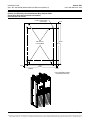
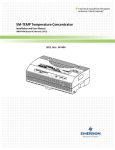
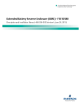
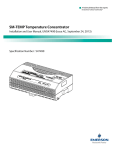
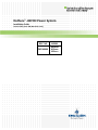
NetSure™ -48V DC Power System Installation Guide Section 5957 (Issue AM, March 26, 2014) SPEC. NO. MODEL 582140000 802NLDB 802NLEB 802NL-B Business-Critical Continuity™, Emerson Network Power, and the Emerson Network Power logo are trademarks and service marks of Emerson Electric Co. ® ® Lorain and Vortex are registered trademarks of Emerson Network Power, Energy Systems, North America, Inc. NetSure™, NetSpan™, NetReach™, NetXtend™, and NetPerform™ are trademarks of Emerson Network Power, Energy Systems, North America, Inc. All other trademarks are the property of their respective owners. The products covered by this instruction manual are manufactured and/or sold by Emerson Network Power, Energy Systems, North America, Inc. The information contained in this document is subject to change without notice and may not be suitable for all applications. While every precaution has been taken to ensure the accuracy and completeness of this document, Emerson Network Power, Energy Systems, North America, Inc. assumes no responsibility and disclaims all liability for damages resulting from use of this information or for any errors or omissions. Refer to other local practices or building codes as applicable for the correct methods, tools, and materials to be used in performing procedures not specifically described in this document. This document is the property of Emerson Network Power, Energy Systems, North America, Inc. and contains confidential and proprietary information owned by Emerson Network Power, Energy Systems, North America, Inc. Any copying, use, or disclosure of it without the written permission of Emerson Network Power, Energy Systems, North America, Inc. is strictly prohibited. Copyright © 2014, Emerson Network Power, Energy Systems, North America, Inc. All rights reserved throughout the world. Installation Guide Spec. No. 582140000 (Models 802NLDB, 802NLEB and 802NL-B) Section 5957 Issue AM, March 26, 2014 Preface This document (Section 5957) provides an Installation Guide for Power System Models 802NLDB (208V Input Power/Distribution and Power Only Bays), 802NLEB (480V Input Power/Distribution and Power Only Bays, and 802NL-B (Distribution Only Bay); Spec. No. 582140000. This is a condense version of the Installation Instructions (Section 5876). Section 5876 can be accessed via the CD (Electronic Documentation Package) furnished with your system. For User Instructions, refer to Section 5877 provided on the CD (Electronic Documentation Package) furnished with your system. Refer to SAG582140000 (System Application Guide) for additional information. The SAG can be accessed via the CD (Electronic Documentation Package) furnished with your system. For a color MCA Menu Tree, refer to Section 5886. Section 5886 is provided in the separate INSTALLATION MANUAL and the CD CARRIER MANUAL (it is also provided on the CD). Your Power System may contain an optional LMS Monitoring System, refer to Section 5879 (LMS1000 Installation Instructions) and Section 5847 (LMS1000 User Instructions) provided on the CD (Electronic Documentation Package) furnished with your system. Danger: INSTALLERS MUST FOLLOW APPROVED SAFETY PROCEDURES. This system operates from AC voltage capable of producing fatal electrical shock. AC input power must be completely disconnected from the branch circuits wiring used to provide power to the system before any electrical connections are made. DO NOT apply AC power to the system until all electrical connections have been completed and checked. This system may also require battery to be connected. Although battery voltage is not hazardously high, the battery can deliver large amounts of current. Exercise extreme caution not to inadvertently contact or have any tool inadvertently contact a battery terminal or exposed wire connected to a battery terminal. NEVER allow a metal object, such as a tool, to contact more than one termination at a time, or to simultaneously contact a termination and a grounded object. Even a momentary short circuit can cause explosion and injury. Remove watches, rings, or other jewelry before connecting battery leads. Make the DC (battery) connections last. Make all other electrical connections without DC input power applied to the system. Warning: Before handling any circuit card, read and follow the instructions contained on the Static Warning Page located at the beginning of this document. A static wrist strap grounded through a one megohm resistor should always be worn when handling the circuit cards. Note: Apply electrical anti-oxidation compound to mating surfaces of busbars before connecting together. Wiring Considerations For recommended wire sizes, crimp lugs, branch circuit protection, alarm relay contact ratings, and general wiring information and restrictions; refer to System Application Guide SAG582140000. The SAG can be accessed via the CD (Electronic Documentation Package) furnished with your system. Page 1 This document is property of Emerson Network Power, Energy Systems, North America, Inc. and contains confidential and proprietary information owned by Emerson Network Power, Energy Systems, North America, Inc. Any copying, use, or disclosure of it without the written permission of Emerson Network Power, Energy Systems, North America, Inc. is strictly prohibited. Section 5957 Issue AM, March 26, 2014 Installation Guide Spec. No. 582140000 (Models 802NLDB, 802NLEB and 802NL-B) Refer to drawing 031110100 for lug crimping information. Refer to drawings 031110200 and 031110300 for additional lug information. These are located in the Installation Manual. All wiring and branch circuit protection should follow the current edition of the American National Standards Institute (ANSI) approved National Fire Protection Association's (NFPA) National Electrical Code (NEC), and applicable local codes. For operation in countries where the NEC is not recognized, follow applicable codes. For field wiring, use wires suitable for at least 75°C. Installation Acceptance Checklist Placing the Bays and Installing Internal/External Busbars Bays (and PDSC if furnished) Bolted Together (if required) and Mounted to Floor Bay-to-Bay Busbar Links Installed (if required) PDSC (if furnished) AC Input Connectors Connected to Power/Distribution Bay External Top-Mount Busbar Assemblies Installed (if furnished) Installing Distribution Devices, MCA Relay Circuit Cards, and MCA I/O Circuit Cards Distribution Fuses and Circuit Breakers Installed Distribution Lug Adapter Plates Installed MCA Customer Alarm Relay Circuit Card(s) Installed (if required) MCA I/O Circuit Card(s) Installed (if required) Making Electrical Connections MCA Network Bay Interconnections Made MCA Battery Charge Digital Temperature Compensation Probe Mounted and Connected (if furnished) MCA External Alarm, Reference, and Control Connections Made Connections Made to all MCA I/O Circuit Cards Installed LMS Local Port Connection Made (If Required) Bay(s) Frame Grounding Connections Made Bay(s) Load Connections Made Bay(s) AC Input and AC Input Ground Connections Made Battery Connections Made All Shields and Cover Panels in Place Installing the Rectifiers and Setting Switch Options Rectifiers Installed MCA and Router Circuit Cards Switches Set Distribution Bus Monitoring Circuit Cards Jumper Set Page 2 This document is property of Emerson Network Power, Energy Systems, North America, Inc. and contains confidential and proprietary information owned by Emerson Network Power, Energy Systems, North America, Inc. Any copying, use, or disclosure of it without the written permission of Emerson Network Power, Energy Systems, North America, Inc. is strictly prohibited. Installation Guide Spec. No. 582140000 (Models 802NLDB, 802NLEB and 802NL-B) Section 5957 Issue AM, March 26, 2014 Floor Mounting Hole Dimensions Primary and Secondary Power/Distribution Bays without PDSC (Power Only Bays Have the Same Hole Pattern) (all dimensions in inches) 0.750 X 2.000 SLOT (4 PLACES) 3/8-16 Floor Leveling Bolts 3.44 30.00 24.12 2.44 19.62 24.00 2.19 FRONT 2.19 Floor Hole Drilling Pattern Power/Distribution Bay Page 3 This document is property of Emerson Network Power, Energy Systems, North America, Inc. and contains confidential and proprietary information owned by Emerson Network Power, Energy Systems, North America, Inc. Any copying, use, or disclosure of it without the written permission of Emerson Network Power, Energy Systems, North America, Inc. is strictly prohibited. Section 5957 Issue AM, March 26, 2014 Installation Guide Spec. No. 582140000 (Models 802NLDB, 802NLEB and 802NL-B) Floor Mounting Hole Dimensions Primary and Secondary Power/Distribution Bays with PDSC (all dimensions in inches) AC POWER DISTRIBUTION SERVICE CABINET 0.750 X 2.000 SLOT (4 PLACES) POWER/ DISTRIBUTION BAY 3/8-16 Floor Leveling Bolts 2.11 5.63 9.85 2.11 3/8-16 Floor Leveling Bolts 2.19 19.62 24.00 0.750 X 2.000 SLOT (4 PLACES) 3.44 30.00 24.12 2.44 2.19 FRONT Floor Hole Drilling Pattern Power/Distribution Bay and PDSC Page 4 This document is property of Emerson Network Power, Energy Systems, North America, Inc. and contains confidential and proprietary information owned by Emerson Network Power, Energy Systems, North America, Inc. Any copying, use, or disclosure of it without the written permission of Emerson Network Power, Energy Systems, North America, Inc. is strictly prohibited. Installation Guide Spec. No. 582140000 (Models 802NLDB, 802NLEB and 802NL-B) Section 5957 Issue AM, March 26, 2014 Floor Mounting Hole Dimensions Distribution Only Bay (all dimensions in inches) 3/8-16 Welded Nut (4) 31.375 27.625 25.875 23.250 19.500 26.625 19.500 24.000 30.000 25.375 3.063 1.750 1.875 2.750 4.063 5.937 0.812 Dia. (8 PLACES) Front Page 5 This document is property of Emerson Network Power, Energy Systems, North America, Inc. and contains confidential and proprietary information owned by Emerson Network Power, Energy Systems, North America, Inc. Any copying, use, or disclosure of it without the written permission of Emerson Network Power, Energy Systems, North America, Inc. is strictly prohibited. Section 5957 Issue AM, March 26, 2014 Installation Guide Spec. No. 582140000 (Models 802NLDB, 802NLEB and 802NL-B) Bolting Power/Distribution Bay to PDSC Cabinet Holes for Bolting Power/Distribution Bays and PDSCs Togethrer Bay/Cabinet Sides Hardware Build-Up: (use ground washers in center tie points each side) Bolt, Ground Washer, Bay/Cabinet Sides, Ground Washer, Nut Bay/Cabinet Sides Hardware Build-Up: (use in remaining connection points) Bolt, Lock Washer, Flat Washer, Bay/Cabinet Sides, Flat Washer, Lock Washer, Nut Page 6 This document is property of Emerson Network Power, Energy Systems, North America, Inc. and contains confidential and proprietary information owned by Emerson Network Power, Energy Systems, North America, Inc. Any copying, use, or disclosure of it without the written permission of Emerson Network Power, Energy Systems, North America, Inc. is strictly prohibited. Installation Guide Spec. No. 582140000 (Models 802NLDB, 802NLEB and 802NL-B) Section 5957 Issue AM, March 26, 2014 Bolting Power/Distribution Bay to Power/Distribution Bay Holes for Bolting Power/Distribution Bays Togethrer Bay/Bay Sides Hardware Build-Up: (use ground washers in center tie points each side) Bolt, Ground Washer, Bay/Cabinet Sides, Ground Washer, Nut Bay/Bay Sides Hardware Build-Up: (use in remaining connection points) Bolt, Lock Washer, Flat Washer, Bay/Cabinet Sides, Flat Washer, Lock Washer, Nut Page 7 This document is property of Emerson Network Power, Energy Systems, North America, Inc. and contains confidential and proprietary information owned by Emerson Network Power, Energy Systems, North America, Inc. Any copying, use, or disclosure of it without the written permission of Emerson Network Power, Energy Systems, North America, Inc. is strictly prohibited. Section 5957 Issue AM, March 26, 2014 Installation Guide Spec. No. 582140000 (Models 802NLDB, 802NLEB and 802NL-B) Installing Power/Distribution Bay to Power/Distribution Bay Negative and Positive Busbar Links (WITHOUT PDSC) POSITIVE BUSBAR LINK 3/8-16 x 1-1/2" Bolt 3/8" Belleville Lock Washer 3/8" Belleville Lock Washer (concave side of Belleville Lock Washers face each other) 3/8” Hardened Flat Washer (10 Places per Busbar) NEGATIVE BUSBAR LINK Slide Busbar Links Under Bays' Upright Channels. Use Bolt Holes as Shown in Illustration. Torque to 180 in-lbs. Page 8 This document is property of Emerson Network Power, Energy Systems, North America, Inc. and contains confidential and proprietary information owned by Emerson Network Power, Energy Systems, North America, Inc. Any copying, use, or disclosure of it without the written permission of Emerson Network Power, Energy Systems, North America, Inc. is strictly prohibited. Installation Guide Spec. No. 582140000 (Models 802NLDB, 802NLEB and 802NL-B) Section 5957 Issue AM, March 26, 2014 Installing Power/Distribution Bay to Power/Distribution Bay Negative and Positive Busbar Links (WITH PDSC) POSITIVE BUSBAR LINK 3/8-16 x 1-1/2" Bolt 3/8" Belleville Lock Washer 3/8" Belleville Lock Washer (concave side of Belleville Lock Washers face each other) 3/8” Hardened Flat Washer (10 Places per Busbar) NEGATIVE BUSBAR LINK Slide Busbar Links Under Bays' Upright Channels. Use Bolt Holes as Shown in Illustration. Torque to 180 in-lbs. Busbar Link Cover Shield (installed after all mounting and electrical connection procedures are completed) Page 9 This document is property of Emerson Network Power, Energy Systems, North America, Inc. and contains confidential and proprietary information owned by Emerson Network Power, Energy Systems, North America, Inc. Any copying, use, or disclosure of it without the written permission of Emerson Network Power, Energy Systems, North America, Inc. is strictly prohibited. Section 5957 Issue AM, March 26, 2014 Installation Guide Spec. No. 582140000 (Models 802NLDB, 802NLEB and 802NL-B) Installing Power/Distribution Bay to Power/Distribution Bay Negative and Positive Busbar Links – New Style Bay Connected to an Existing Older Style Bay Newer Style Bay Existing Older Style Bay Newer Style Bay Existing Older Style Bay POSITIVE BUSBAR LINK 3/8-16 x 1-1/2" Bolt 3/8" Belleville Lock Washer 3/8" Belleville Lock Washer (concave side of Belleville Lock Washers face each other) 3/8” Hardened Flat Washer NEGATIVE BUSBAR LINK Newer Style Bay side, use bolt holes as shown in illustration. List 1 and 11 shown. List 2 and 12 w/ List 30 or 31 similar. Existing Older Style Bay side, use ALL bolt holes. Slide Busbar Links Under Bays' Upright Channels. Torque to 180 in-lbs. Page 10 This document is property of Emerson Network Power, Energy Systems, North America, Inc. and contains confidential and proprietary information owned by Emerson Network Power, Energy Systems, North America, Inc. Any copying, use, or disclosure of it without the written permission of Emerson Network Power, Energy Systems, North America, Inc. is strictly prohibited. Installation Guide Spec. No. 582140000 (Models 802NLDB, 802NLEB and 802NL-B) Section 5957 Issue AM, March 26, 2014 Connecting Rectifier Mounting Position AC Input Connectors to PDSC (Lists 2 and 12 Only) to PCU Mtg. Pos. #1 A B C to PCU Mtg. Pos. #2 A B C to PCU Mtg. Pos. #3 A B C to PCU Mtg. Pos. #4 A B C to PCU Mtg. Pos. #5 A B C to PCU Mtg. Pos. #6 A B C to PCU Mtg. Pos. #7 A B C to PCU Mtg. Pos. #8 A B C to PCU Mtg. Pos. #9 A B C to PCU Mtg. Pos. #10 A B C Connectors in PDSC Power/Distribution Bay PDSC Power/Distribution Bay PDSC Torque to 23 in-lbs. Row of PCU Mtg. Pos. AC Input Connectors Row of PDSC PCU AC Input Connectors Page 11 This document is property of Emerson Network Power, Energy Systems, North America, Inc. and contains confidential and proprietary information owned by Emerson Network Power, Energy Systems, North America, Inc. Any copying, use, or disclosure of it without the written permission of Emerson Network Power, Energy Systems, North America, Inc. is strictly prohibited. Section 5957 Issue AM, March 26, 2014 Installation Guide Spec. No. 582140000 (Models 802NLDB, 802NLEB and 802NL-B) Power/Distribution Bay External Top-Mount Horizontal Battery Input Busbar Assembly (P/N 554873) Assembly Procedure Step 1 STEP 1 Install “Main Positive Busbar” onto Bay’s Positive Busbar. Hand-tighten hardware. (1) Main Positive Busbar, P/N 554877 Note: Apply Electrical Anti-Oxidation Compound to Busbar Mating Surfaces. (12) 3/8” Flat Washer, P/N 214204100 (12) 3/8” Belleville Washer, P/N 214825000 (12) 3/8-16 Hex Nut, P/N 228567100 Hand-tighten. Note: Concave Side of Belleville Washer Faces Busbar, Convex Side Faces Hex Nut. Rear Top of Bay Belleville Washer install between Hex Nut and Flat Washer. Do the following first before assembly: 1. Remove 552402 (1) and 116638 (4) from Bay. 2. Mount 554880 to the 554877 with 116638 (3). Assembled View Page 12 This document is property of Emerson Network Power, Energy Systems, North America, Inc. and contains confidential and proprietary information owned by Emerson Network Power, Energy Systems, North America, Inc. Any copying, use, or disclosure of it without the written permission of Emerson Network Power, Energy Systems, North America, Inc. is strictly prohibited. Installation Guide Spec. No. 582140000 (Models 802NLDB, 802NLEB and 802NL-B) Section 5957 Issue AM, March 26, 2014 Power/Distribution Bay External Top-Mount Horizontal Battery Input Busbar Assembly (P/N 554873) Assembly Procedure Step 2 STEP 2 Install “Support Bar” and “Related Hardware” onto Top of Bay. (2) Threaded Insulator, P/N 245857200 Torque to 715 In-lbs. (2) Support Bar Clip, P/N 351322300 (2) Support Bar, P/N 237790100 (2) Support Bar Clip, P/N 351322300 (2) 5/8” Lock Washer, P/N 215111800 (2) 5/8” Hex Nut, P/N 228580900 Leave 1/4” Space Between Bottom of Nut and Top of Bay. (2) 5/8-11 x 7” Threaded Rod, P/N 334317000 Rear Top of Bay Assembled View Page 13 This document is property of Emerson Network Power, Energy Systems, North America, Inc. and contains confidential and proprietary information owned by Emerson Network Power, Energy Systems, North America, Inc. Any copying, use, or disclosure of it without the written permission of Emerson Network Power, Energy Systems, North America, Inc. is strictly prohibited. Section 5957 Issue AM, March 26, 2014 Installation Guide Spec. No. 582140000 (Models 802NLDB, 802NLEB and 802NL-B) Power/Distribution Bay External Top-Mount Horizontal Battery Input Busbar Assembly (P/N 554873) Assembly Procedure Step 3 STEP 3 Install “Main Negative Busbar” onto Bay’s Negative Busbar. Hand-tighten hardware. (1) Main Negative Busbar, P/N 554875 Note: Apply Electrical Anti-Oxidation Compound to Busbar Mating Surfaces. (8) 3/8” Flat Washer, P/N 214204100 (8) 3/8” Belleville Washer, P/N 214825000 (8) 3/8-16 Hex Nut, P/N 228567100 Hand-Tighten Note: Concave Side of Belleville Washer Faces Busbar, Convex Side Faces Hex Nut. Belleville Washer Install between Hext Nut and Flat Washer. Mount 554876 to the 554875. Hardware: 214204100 (4) 214825000 (4) 228567100 (4) Assembled View Rear Top of Bay Page 14 This document is property of Emerson Network Power, Energy Systems, North America, Inc. and contains confidential and proprietary information owned by Emerson Network Power, Energy Systems, North America, Inc. Any copying, use, or disclosure of it without the written permission of Emerson Network Power, Energy Systems, North America, Inc. is strictly prohibited. Installation Guide Spec. No. 582140000 (Models 802NLDB, 802NLEB and 802NL-B) Section 5957 Issue AM, March 26, 2014 Power/Distribution Bay External Top-Mount Horizontal Battery Input Busbar Assembly (P/N 554873) Assembly Procedure Step 4 STEP 4 Install “Horizontal Landing Negative Busbar” onto “Main Negative Busbar”. Torque to 180 in-lbs. (6) 3/8-16 x 1-1/4” Bolt, P/N 227646800 (6) 3/8” Belleville Washer, P/N 214825000 (6) 3/8" Flat Washer, P/N 214204100 Note: Concave Side of Belleville Washer Faces Busbar, Convex Side Faces Bolt Head. Belleville Washer install between Bolt Head and Flat Washer. (1) Horizontal Landing Negative Busbar, P/N 514434 Note: Apply Electrical Anti-Oxidation Compound to Busbar Mating Surfaces. Rear Top of Bay Assembled View Page 15 This document is property of Emerson Network Power, Energy Systems, North America, Inc. and contains confidential and proprietary information owned by Emerson Network Power, Energy Systems, North America, Inc. Any copying, use, or disclosure of it without the written permission of Emerson Network Power, Energy Systems, North America, Inc. is strictly prohibited. Section 5957 Issue AM, March 26, 2014 Installation Guide Spec. No. 582140000 (Models 802NLDB, 802NLEB and 802NL-B) Power/Distribution Bay External Top-Mount Horizontal Battery Input Busbar Assembly (P/N 554873) Assembly Procedure Step 5 STEP 5 Install "Threaded Insulators" onto "Horizontal Landing Negative Busbar". (2) Threaded Insulator, P/N 245857200 Hand-Tighten (2) 5/8-11 x 1-1/4" Threaded Rod, P/N 334315700 (2) Threaded Insulator, P/N 245857200 Hand-Tighten (2) 5/8-11 x 1-1/2" Threaded Rod, P/N 334315900 Rear Top of Bay Assembled View Page 16 This document is property of Emerson Network Power, Energy Systems, North America, Inc. and contains confidential and proprietary information owned by Emerson Network Power, Energy Systems, North America, Inc. Any copying, use, or disclosure of it without the written permission of Emerson Network Power, Energy Systems, North America, Inc. is strictly prohibited. Installation Guide Spec. No. 582140000 (Models 802NLDB, 802NLEB and 802NL-B) Section 5957 Issue AM, March 26, 2014 Power/Distribution Bay External Top-Mount Horizontal Battery Input Busbar Assembly (P/N 554873) Assembly Procedure Step 6 STEP 6 Install "Horizontal Landing Positive Busbar" onto "Main Positive Busbar". (2) 5/8-11 x 1" Bolt, P/N 227655100 Torque to 715 in-lbs. (2) 5/8" Lock Washer, P/N 215111800 (2) 5/8" Flat Washer, P/N 214201300 (1) Horizontal Landing Positive Busbar, P/N 514436 Note: Apply Electrical Anti-Oxidation Compound to Busbar Mating Surfaces. Torque to 180 in-lbs. (6) 3/8" Flat Washer, P/N 214204100 (6) 3/8" Belleville Washer, P/N 214825000 (6) 3/8-16 x 1-1/4" Bolt, P/N 227646800 Note: Concave Side of Belleville Washer Faces Busbar, Convex Side Faces Bolt Head. Rear Top of Bay Belleville Washer install between Bolt Head and Flat Washer. Assembled View Page 17 This document is property of Emerson Network Power, Energy Systems, North America, Inc. and contains confidential and proprietary information owned by Emerson Network Power, Energy Systems, North America, Inc. Any copying, use, or disclosure of it without the written permission of Emerson Network Power, Energy Systems, North America, Inc. is strictly prohibited. Section 5957 Issue AM, March 26, 2014 Installation Guide Spec. No. 582140000 (Models 802NLDB, 802NLEB and 802NL-B) Power/Distribution Bay External Top-Mount Horizontal Battery Input Busbar Assembly (P/N 554873) Assembly Procedure Step 7 STEP 7 Final Torque Rear Top of Bay Torque these connections to 180 in-lbs (20 places). Page 18 This document is property of Emerson Network Power, Energy Systems, North America, Inc. and contains confidential and proprietary information owned by Emerson Network Power, Energy Systems, North America, Inc. Any copying, use, or disclosure of it without the written permission of Emerson Network Power, Energy Systems, North America, Inc. is strictly prohibited. Installation Guide Spec. No. 582140000 (Models 802NLDB, 802NLEB and 802NL-B) Section 5957 Issue AM, March 26, 2014 Power/Distribution Bay Busbar Shield Kit (P/N 528482) Assembly Procedure Page 19 This document is property of Emerson Network Power, Energy Systems, North America, Inc. and contains confidential and proprietary information owned by Emerson Network Power, Energy Systems, North America, Inc. Any copying, use, or disclosure of it without the written permission of Emerson Network Power, Energy Systems, North America, Inc. is strictly prohibited. Section 5957 Issue AM, March 26, 2014 Installation Guide Spec. No. 582140000 (Models 802NLDB, 802NLEB and 802NL-B) Power/Distribution Bay External Top-Mount Ground (Load Return) Busbar Assembly (P/N 514688 or 514689) Assembly Procedure Step 1 STEP 1 Install "Threaded Insulators". (1) Threaded Insulator, P/N 245857200 Hand-Tighten (1) 5/8-11 x 1-1/4" Threaded Rod, P/N 334315700 (1) Threaded Insulator, P/N 245857200 Previously Assembled Kit P/N 554873 Rear Top of Bay (1) 5/8" Flat Washer, P/N 214201300 (1) 5/8" Lock Washer, P/N 215111800 (1) 5/8-11 x 1" Bolt, P/N 227655100 Torque to 715 in-lbs. Assembled View Page 20 This document is property of Emerson Network Power, Energy Systems, North America, Inc. and contains confidential and proprietary information owned by Emerson Network Power, Energy Systems, North America, Inc. Any copying, use, or disclosure of it without the written permission of Emerson Network Power, Energy Systems, North America, Inc. is strictly prohibited. Installation Guide Spec. No. 582140000 (Models 802NLDB, 802NLEB and 802NL-B) Section 5957 Issue AM, March 26, 2014 Power/Distribution Bay External Top-Mount Ground (Load Return) Busbar Assembly (P/N 514688 or 514689) Assembly Procedure Step 2A STEP 2A Install "Busbars". (see Step 2B for Bolt Hole Identification) (see Step 2C for Assembled View) * Use "Spacer Busbars" or "Spacer Insulators" on end bays or stand-alone bays. For multiple bays, 'sandwich' busbars of adjacent "Busbar Assemblies" together. Note: Apply Electrical Anti-Oxidation Compound to all Busbar Mating Surfaces. Busbar Assy P/N 514688 (4) 3/8-16 x 2" Bolt, P/N 227647400 Torque to 180 in-lbs. or 3/8-16 x 2-3/4" Bolt, P/N 227647700 and (4) 3/8" Flat Washer, P/N 214204100 Busbar Assy P/N 514689 Busbar, P/N 514467 P/N 514689 Only Spacer Busbar, P/N 514472, or Busbar from Next Bay* Busbar, P/N 514522 Spacer Busbar, P/N 514472, or Busbar from Next Bay* P/N 514689 Only Busbar, P/N 514467 P/N 514689 Only Spacer Busbar, P/N 514472, or Busbar from Next Bay* (1) 5/8-11 x 1-3/4" Bolt, P/N 227653800 or Torque to 715 in-lbs. 5/8-11 x 2-3/4" Bolt, P/N 227653900 and (1) 5/8" Lock Washer, P/N 215111800 and (1) 5/8" Flat Washer, P/N 214201300 Spacer Insulator, P/N 514473, or Busbar from Next Bay* P/N 514689 Only Busbar, P/N 514467 Spacer Insulator, P/N 514473, or Busbar from Next Bay* Busbar, P/N 514467 P/N 514689 Only Spacer Insulator, P/N 514473, or Busbar from Next Bay* P/N 514689 Only Busbar, P/N 514467 Busbar, P/N 514541 Spacer Busbar, P/N 514472, or Busbar from Next Bay* (4) 3/8" Belleville Washer P/N 214825000 (4) 3/8-16 Hex Nut P/N 228567100 Spacer Insulator, P/N 514473, or Busbar from Next Bay* Busbar, P/N 514467 Note: Concave Side of Belleville Washer Faces Busbar, Convex Side Faces Nut. Previously Assembled Kit P/N 554873 Rear Top of Bay (6) 3/8" Flat Washer P/N 214204100 (6) 3/8" Belleville Washer P/N 214825000 (6) 3/8-16 x 1-1/4" Bolt Torque to 180 in-lbs. P/N 227646800 Note: Concave Side of Belleville Washer Faces Busbar, Convex Side Faces Bolt Head. Belleville Washer install between Bolt Head and Flat Washer. Page 21 This document is property of Emerson Network Power, Energy Systems, North America, Inc. and contains confidential and proprietary information owned by Emerson Network Power, Energy Systems, North America, Inc. Any copying, use, or disclosure of it without the written permission of Emerson Network Power, Energy Systems, North America, Inc. is strictly prohibited. Section 5957 Issue AM, March 26, 2014 Installation Guide Spec. No. 582140000 (Models 802NLDB, 802NLEB and 802NL-B) Power/Distribution Bay External Top-Mount Ground (Load Return) Busbar Assembly (P/N 514688 or 514689) Assembly Procedure Step 2B STEP 2B Install "Busbars". (Bolt Hole Identification) Page 22 This document is property of Emerson Network Power, Energy Systems, North America, Inc. and contains confidential and proprietary information owned by Emerson Network Power, Energy Systems, North America, Inc. Any copying, use, or disclosure of it without the written permission of Emerson Network Power, Energy Systems, North America, Inc. is strictly prohibited. Installation Guide Spec. No. 582140000 (Models 802NLDB, 802NLEB and 802NL-B) Section 5957 Issue AM, March 26, 2014 Power/Distribution Bay External Top-Mount Ground (Load Return) Busbar Assembly (P/N 514688 or 514689) Assembly Procedure Step 2C STEP 2C Install "Busbars". (Assembled Views) Spacer Busbars or Spacer Insulators Installed Previously Assembled Kit P/N 554873 Assembled Views No Spacer Busbars or Spacer Insulators. Busbars of Adjacent Assemblies 'Sandwich' and Bolted Together. Previously Assembled Kit P/N 554873 Page 23 This document is property of Emerson Network Power, Energy Systems, North America, Inc. and contains confidential and proprietary information owned by Emerson Network Power, Energy Systems, North America, Inc. Any copying, use, or disclosure of it without the written permission of Emerson Network Power, Energy Systems, North America, Inc. is strictly prohibited. Section 5957 Issue AM, March 26, 2014 Installation Guide Spec. No. 582140000 (Models 802NLDB, 802NLEB and 802NL-B) Power/Distribution Bay External Top-Mount Ground (Load Return) Busbar Assembly (P/N 514688 or 514689) Assembly Procedure Step 3 STEP 3 Install "Cover" Mounting Standoffs. (2) Standoff, P/N 117843 (2) 1/4" Flat Washer, P/N 214110100 (2) 1/4" Lock Washer, P/N 215111100 (2) 1/4-20 x 1/2" Bolt, P/N 227640200 Torque to 84 in-lbs. Rear Top of Bay Previously Assembled Kit P/N 554873 DO NOT PERFORM THIS STEP if you are going to install "Load Return Lug Extension Busbar Assembly" P/N 514543 Use These Holes Assembled View Page 24 This document is property of Emerson Network Power, Energy Systems, North America, Inc. and contains confidential and proprietary information owned by Emerson Network Power, Energy Systems, North America, Inc. Any copying, use, or disclosure of it without the written permission of Emerson Network Power, Energy Systems, North America, Inc. is strictly prohibited. Installation Guide Spec. No. 582140000 (Models 802NLDB, 802NLEB and 802NL-B) Section 5957 Issue AM, March 26, 2014 Power/Distribution Bay External Top-Mount Ground (Load Return) Busbar Assembly (P/N 514688 or 514689) Assembly Procedure Step 4 STEP 4 (2) 1/4-20 x 1/2" Bolt, P/N 227640200 (2) 1/4" Lock Washer, P/N 215111100 Install "Covers". (2) 1/4" Flat Washer, P/N 214110100 P/N 514520 P/N 51452 Torque to 45 in-lbs. 1 (2) 10-32 Lock Nut, P/N 104564 (2) 10-32 x 3/4" Tap Screw, P/N 218706500 DO NOT PERFORM THIS STEP if you are going to install "Load Return Lug Extension Busbar Assembly" P/N 514543 Rear Top of Bay Assembled View Page 25 This document is property of Emerson Network Power, Energy Systems, North America, Inc. and contains confidential and proprietary information owned by Emerson Network Power, Energy Systems, North America, Inc. Any copying, use, or disclosure of it without the written permission of Emerson Network Power, Energy Systems, North America, Inc. is strictly prohibited. Section 5957 Issue AM, March 26, 2014 Installation Guide Spec. No. 582140000 (Models 802NLDB, 802NLEB and 802NL-B) Power/Distribution Bay External Top-Mount Ground (Load Return) Busbar Assembly (P/N 514690 or 514691) Assembly Procedure Step 1 STEP 1 Install "Threaded Insulators". (1) Threaded Insulator, P/N 245857200 Hand-Tighten (1) 5/8-11 x 1-1/4" Threaded Rod, P/N 334315700 (1) Threaded Insulator, P/N 245857200 Previously Assembled Kit P/N 554873 Rear Top of Bay (1) 5/8" Flat Washer, P/N 214201300 (1) 5/8" Lock Washer, P/N 215111800 (1) 5/8-11 x 1" Bolt, P/N 227655100 Torque to 715 in-lbs. Assembled View Page 26 This document is property of Emerson Network Power, Energy Systems, North America, Inc. and contains confidential and proprietary information owned by Emerson Network Power, Energy Systems, North America, Inc. Any copying, use, or disclosure of it without the written permission of Emerson Network Power, Energy Systems, North America, Inc. is strictly prohibited. Installation Guide Spec. No. 582140000 (Models 802NLDB, 802NLEB and 802NL-B) Section 5957 Issue AM, March 26, 2014 Power/Distribution Bay External Top-Mount